
Fire-Resistance Testing Procedures for Construction Elements—A Review
by
 , , , and
Shashikant Chaturvedi
1,
Ajitanshu Vedrtnam
1,2,* ,
,
Maged A. Youssef
3 ,
,
Martin T. Palou
2,
Gonzalo Barluenga
4 and
Kishor Kalauni
1 1
Department of Mechanical Engineering, Invertis University, Bareilly 243001, UP, India
2
Institute of Construction and Architecture, Slovak Academy of Science, 84503 Bratislava, Slovakia
3
Civil and Environmental Engineering, Western University, 1151 Richmond Street North, London, ON N6A 5B9, Canada
4
Departamento de Arquitectura, Escuela de Arquitectura, Universidad de Alcalá, 28801 Madrid, Spain
*
Author to whom correspondence should be addressed.
Fire 2023, 6(1), 5; https://doi.org/10.3390/fire6010005
Submission received: 19 October 2022
/
Revised: 14 December 2022
/
Accepted: 19 December 2022
/
Published: 24 December 2022
Abstract
:Fire accidents are a significant risk to human life and civil infrastructure. As a countermeasure, the regulatory bodies of different countries have established standards for evaluating the performance of construction elements during fire exposure. ISO 834 is the globally accepted fire-resistance testing standard. Other standards include ASTM E119, BS 476, IS 3809, JIS A 1304, AS 1503, EN 1363, and GB/T 9978, which are utilized by the US, Britain, India, Japan, Australia, Europe, and China, respectively. This article presents a summary and comparison of the fire-resistance testing standards. In reality, standard tests for isolated structural members may not efficiently portray realistic fire scenarios due to the fire location, its intensity, etc. Thus, researchers have utilized a variety of specialized setups and full-scale non-standard fire tests to fulfill their research objectives. The article includes a summary of selected full-scale, ad hoc, and specialized setups that were reported in the literature. The article highlights the need for timely updates of fire standards to accommodate the testing of newly developed construction materials, structural systems, and possible regional fire scenarios. The article also identifies the research areas that require significant focus in experimental structural fire-resistant testing.
1. Introduction
Fire accidents are a global challenge. The National Crime Records Bureau (NCRB) reported an increase in cases of fire accidents in India over the past years [1]. The NCRB data recorded 113,961 deaths (62 per day due, on average) due to fire disasters between 2010 to 2014 [1,2]. India’s 2017 risk survey reported that fire accidents caused 17,700 deaths; 42.1% of them happened in residential buildings in 2015 [1]. The National Fire Protection Association said that, during 2018, there were 1,318,500 fire incidents, 3655 deaths, and a $25.6 billion loss in the US, out of which 74% of the deaths were during house fires [3]. The fire resistance of building elements is addressed during the design stage to curb fire incidents. The regulatory bodies of different countries have established guidelines for fire tests on construction elements. The tests addressed by these guidelines include external fire exposure, ignitibility, fire propagation, non-combustibility, surface spread of blaze, and fire resistance. This article focuses on the fire-resistance tests, which are used to assess the construction element’s ability to withstand mechanical load for specified fire duration and to act as a fire separation. It assists in choosing appropriate fire-resistive elements based on the intended application. Although it is impossible to predict the actual fire situation, the fire-resistance test defines the minimum fire resistance that should be maintained to safeguard structures during a fire incident.
Researchers do not always adopt fire testing standards [4]. The standard time–temperature curves suggested by the regulations are unreal and do not follow the principles of fire dynamics. The heating period given in the standards is questionable. The loading and boundary conditions specified in the standard tests cannot be compared to real building fire incidents [4]. Despite all of these limitations, the reproducibility and control achieved during experimentation, which follows the regulations, prove their usefulness to consistently measure the structural fire performance of construction elements. Table 1 summarizes the development of fire-resistance testing procedures in chronological order.
Ad hoc fire-resistance testing started in the eighteenth century. However, during the early days, the reproducibility of the results was questionable, as temperature measurement procedures, fuel, and furnace size were not standard [7]. To achieve a reliable performance-based design, which is based on realistic fire performance, researchers conducted full-scale [8,9,10], specialized, and ad hoc tests [11,12]. We have not cited any article in the literature that provides a comprehensive comparison of fire-resistance testing methods for construction materials. In this review, full-scale, specialized, or ad hoc setups are also reported, with an emphasis on the testing procedure and reasons for not choosing standard test methods.
2. Methodology
2.1. Aim and Objectives
The overarching objective of the paper is to compare and review the existing fire-resistance testing procedures and setups suggested by several governing bodies of different countries. The paper provides the following:
- A comparison of different fire-resistance testing standards based on methods of testing, furnace design, specimen size, etc.
- A comparison of performance criteria of different fire-resistance test standards.
- A summary of limitations of different fire-resistance test standards.
- A literature review on fire-resistance testing on building and construction materials.
- A summary of selected full-scale, ad hoc, and specialized setups based on their unique testing procedures reported in the literature.
2.2. Structure of the Review
The article starts with the chronological historical development of fire-resistance testing procedures. Then the article reports a detailed comparison of ASTM, Australian, British, Chinese, DIN, European, Indian, ISO, and Japanese fire-resistance testing standards. After that, the article provides a discussion on the fire-resistance testing of building and construction materials. Lastly, the article summarizes selected full-scale, ad hoc, and specialized setups used in the literature to measure the fire resistance of building materials.
3. Fire-Resistance Test Standards
A fire-resistance test is a measure of load-bearing capacity, structural integrity, fire penetration, fire spread through heat transfer, and insulation. Existing standards recommend the requirements, acceptance criteria, and testing procedures for fire-resistance testing. Some of the fire-resistance test standards for building materials and structures adopted by different countries are shown in Figure 1. This section includes the objectives, setup description, experimental procedure, outcomes, merits, and demerits of the widely used fire-resistant testing standards specified by the regulatory bodies of different countries.
The ASTM E119 describes and measures the response of construction elements to heat and flame under a regulated condition and establishes the duration for which the considered building material can contain a fire [13]. Similarly, Part 4 of the Australian standard AS 1530 [14] details heating requirements, test methods, and principles for determining the fire resistance of walls, ceilings, columns, beams, door sets, air ducts, and other elements. Likewise, the BS 476 Parts 20–23 proposed by British Standard [15] is used to find the capability of an element to resist a standard fire with a specific pressure regime without losing its fire insulation function, its load-bearing capacity, or both. These standards describe the general procedure, apparatus, temperature, and pressure conditions to measure the fire resistance of construction elements, load-bearing elements, non-load-bearing elements, and complete structure. Moreover, the Bureau of Indian Standard IS 3809 [16] explores the extent of resistance for building and construction elements when exposed to fire. The revised version of this standard is based on ISO 834. Correspondingly, the Chinese standards evaluate the burning behavior, provide guidance for fire safety structure, and implement fire protection for building and construction elements to achieve social and economic benefits. They mostly follow ISO 834 [17] and contain similar principles and procedures for defining the fire resistance of construction elements. The German Institute for Standardization, DIN 4102 [18] for fire-resistance testing, specifies methods for fire protection to be applied to building and construction elements to withstand specific heating and pressure conditions. Similarly, the Japanese Industrials Standard JIS 1304 [19] describes buildings’ fire-resistance test method. The principle and methods for these standards also follow ISO 834. Europe has developed the fire-resistance testing standard EN1363 [20], which provides the guidelines for construction and building materials under fire conditions. EN 1363 covers information about the methodology of fire-resistance testing of construction or building materials. The ISO standard for fire-resistance testing specifies a procedure for fire protection applied to building and construction materials. It describes the method that should be carried out to measure the ability of a fire-protection system for a well-defined range of deformations, temperatures, furnaces, thermal characteristics, etc. It is applicable for both reactive and passive fire-protection systems [21]. A comparison of different fire-resistance test standards for construction and building materials, along with their main objectives, is summarized in Table 2, Table 3, Table 4 and Table 5. The fire-resistance testing standards recommend different specimen sizes, the heating method, the standard time/temperature curve, test methods, and their performance criteria.
3.1. Types of Furnaces in Different Fire-Resistance Test Standards
Furnaces are designed to evaluate the fire conditions and fire-resistance ratings of construction elements according to international standards. In general, there are horizontal, vertical, hydraulic tilting, indicative, and miniature fire-resistance test furnaces (Figure 2a–e) [22]. The horizontal furnace, as shown in Figure 2a, is used in the case of slabs, floors, roofs, and ceilings. In contrast, the vertical furnace, as shown in Figure 2b, is used in the case of walls, doors, columns, and partitions. The hydraulic tilting furnace (Figure 2c) is a dual-purpose furnace for fire-resistance tests on a slab, wall, ceiling, and beam in both vertical and horizontal positions. The indicative type of fire-resistance test furnace (Figure 2d) is useful to conduct tests for small samples and assemblies which are exposed to high temperatures. Similarly, the miniature fire-resistance-test furnaces (Figure 2e) are used to conduct fire tests on small vertical samples.
In BS 476, the furnace needs to be designed according to the type of specimen being tested. For vertical separating element (e.g., walls), the furnace should provide the standard heating and pressure condition on one face of the element. However, for horizontal separating elements, the furnace should provide the standard heating and pressure condition from the underside of the element. For beams and columns, the furnace should provide pressure and heating conditions on all four faces. The size of the furnace opening must be larger than the exposed face of the specimen by a minimum ration of 1.5. A pressure-sensing probe should be used to determine the static pressure within the furnace. The time of the commencement of the heating in the furnace should be recorded. The arrangement of pressure and heating applied on the test sample in BS 476 is shown in Figure 3 [23]. The furnace, loading equipment, overpressure-measuring instruments, thermocouple, etc., for the Bureau of Indian standard, IS 3809, are adapted from BS 478 Part 8.
3.2. Specimen Size in Different Fire-Resistance Test Standards
Generally, full-size specimens are required for fire-resistance tests. However, if it is not possible to test a full-size specimen, specimens meeting at least the minimum dimensions can be used (see Table 6).
3.3. Test Procedures in Different Fire-Resistance Test Standards
The heating method and standard temperature/time curve [23] for different fire-resistance testing standards are given in Table 7 and Figure 4.
In ASTM E119, a mixture of gas and air is ignited and fed into the furnace assembly so that the internal temperature rises according to Equation (1). ASTM E119 also covers heat transmission and the ability to withstand a stream from a water hose. The hose-stream test is not required for a construction with a fire rating less than 1 h.
where T is the average temperature recorded by thermocouples arranged within the furnace at time (t) in °C (minimum number of thermocouples = five, one per 1.5 m2 of surface area of floor and wall, two per 1 m of length of beam, and two per 1 m height of column); T0 is the initial furnace temperature in °C; and t is the time in minutes.
In BS 476, the load can be applied by using a hydraulic jack. The specimen support system should have sufficient rigidity and stiffness to restrain the boundaries or the ends of the test specimen, considering thermal deformations and applied loads. Fixed-surface, either type T or type K, thermocouple wires with a maximum diameter of 0.5 mm should be used. A radiometer should be used to measure irradiance within a range of 0 to 100 kW/m2. For measuring the internal temperature of the specimen, internal thermocouples should be used. Figure 5 represents the restraints applied on the specimen in a vertical furnace to measure the fire resistance of a load-bearing wall. Figure 5a shows a 2D representation of a fire-resistance testing on loaded wall. The wall experiences one-sided fire exposure during the test, as depicted in Figure 5b. It can be seen in Figure 5 that a translational fixity is provided at the bottom side. However, there is no dimensional restraint provided on the wall specimen itself to allow the specimen to swell up during fire exposure. Figure 6 shows the different views of dimensional restraint applied on a non-load-bearing wall during the fire-resistance testing. Figure 7 demonstrates the arrangement for the fire testing of floor specimens. The supports restraining the edges of the test specimen shall have sufficient stiffness and rigidity to resist forces exerted by any thermal movement induced during the test and should represent the real service conditions. The floor specimen is placed in the horizontal fire furnace, and the specified loads are applied. The specimen is then exposed to fire from the underside to test its load-bearing capacity, insulation, and integrity. Figure 8 shows the arrangement for the fire testing of column specimens. In this arrangement, the column is protected from lateral deformation at its top and fixed at its bottom. The specified load is applied to the column while exposing the column to fire from four sides. The load bearing, insulation, and integrity are measured in terms of duration causing failure to the considered criterion. Figure 9 demonstrates the test setup for the fire-resistance testing of a beam specimen. The specimen is not restrained in the torsional and lateral directions. Tests generally start by measuring the ambient temperature and applying constant specified loads. Then the specimen is heated in the furnace at controlled temperature and pressure conditions. The temperature–time heating regime should follow Equation (2). For assessment of structures that contain fuels including petrochemicals, the standard hydrocarbon curve, given by Equation (3), should be followed. The mean furnace temperature is measured by thermocouples, which can be either bare nickel chromium/nickel aluminum wire with a diameter of 0.75 to 1.5 mm or nickel chromium/nickel aluminum mineral insulated thermocouple. It is recommended that the thermocouple hot junctions should be arranged at 50 to 150 mm from the surface of the specimen to avoid any damage. The percentage deviation (ρ), Equation (4), between the mean furnace time–temperature curve and the standard time–temperature curve should not exceed 15% at fire duration of 10 min, 10% for fire duration from 10 to 30 min, and 5% for fire duration from 30 min to the termination of the heating period. Moreover, starting with a fire duration of 10 min, the temperature rise in any of the furnace thermocouples should not differ from the standard fire temperature by more than 100 °C. This temperature difference is allowed to reach 200 °C for a construction with combustible material. Regarding the furnace pressure, a positive pressure needs to be established for a duration of 5 min. The pressure gradient within the furnace must not exceed 20 Pa. Deflection of the specimen is monitored and recorded. A radiometer is used to measure the radiation flux emitted from the unexposed face.
where T is the mean furnace temperature in °C at time, t, measured in minutes; and A and B are the area under the mean furnace and standard time–temperature curve, respectively.
The test methods of the Bureau of Indian Standard, IS 3809, are equivalent to those of BS 478. After sample preparation according to JIS A 1304, the specimen is passed through a heat test for 30 min for 1, 2, 3, and 4 h, correspondingly. If the structural parts pass the heat test as given in JIS A 1304, a loaded heat test (L), watering test (W), and shock test (S) are performed. In the JIS A 1304 testing standard, the size of the specimen should be the same as that used for practical purposes. The specimen is then classified based on the tests that it passed. For example, when a specimen is classified as a 2 h heat WS, this means that the sample conceded the 2-hour heat test, the watering test, and shock test. The source of heating could be town gas, propane, fuel, oil, or any other source. The frame supporting the test specimen should be heat proof and designed to hold the test surface at a fixed position. Wall specimens are heated from one side. Columns are heated from four sides. Beams and floors are heated from the underside. If there is any possibility of heating part of the test setup, a gap should be added between the setup and the specimen. The pressure on the specimen’s surface is measured by using a manometer. The heating temperature is measured with a grade 0.75 chromium–aluminum thermocouple of 1 mm diameter.
3.4. Performance Criterion in Different Fire-Resistance Test Standards
The standards define three terms: structural tolerability (the capability of the structure to sustain its load-bearing capacity and stability throughout a fire), integrity (the capability to contain hot gases and flames in one compartment), and insulation (the ability to contain the fire temperature within one compartment with limited temperature increase in other compartments). The functional criteria of fire resistance have necessities for load magnitude for load-bearing structural elements, as well as integrity and insulation for separating elements. In the EN 1363 fire test standard, for load-bearing elements, the test specimen shall not lose the load-bearing property for which it was constructed. For elements such as floors and walls, which have the purpose of separating building compartments, the unexposed side temperature of the specimen shall not be increased by more than 140 °C on average or more than 180 °C at any location. The integrity of elements such as floors and walls, which have the purpose of separating two parts of a building, requires that the elements do not develop cracks and holes through which hot gases or flames can pass. Final integrity failure shall be considered when the breakdown of the specimen takes place. During the fire test, the specimen is exposed to fire under controlled conditions that satisfy the specified time–temperature curve. The fire duration causing failure is recorded. Figure 10 shows the definition of a fire-resistance level of 90/90/90, which means that structural adequacy, integrity, and insulation will satisfy the requirements for at least 90 min [24].
Continuous heating is provided to the specimen until failure, considering one of the performance criteria (load-bearing ability, integrity, and insulation). It should be noted that a specimen is deemed to fail in maintaining its load-bearing ability when the deflection exceeds L/20 or the rate of deflection in mm/minute, measured after reaching a deflection of L/30, exceeds L2/(9000.D), where L and D are the clear span length and height of specimen section in mm, respectively [25]. Integrity failure happens when the fire starts on the unexposed face of the specimen. This can be defined by the ignition of a cotton pad on the unexposed side, or having cracks in the specimen, which allow a 6 mm diameter gauge to enter for a minimum distance of 150 mm or allow a 25 mm gauge to penetrate such that the end of the gauge projects into the furnace. Insulation failure occurs when the mean unexposed face temperature increases by more than 140 °C, or if the temperature recorded at any position on the unexposed side increases by more than 180 °C above the initial mean unexposed side temperature. The performance criterion for the fire test in BS 476 fire test standard is similar to EN 1363 [15]. According to ISO 834, for load-bearing elements, the specimen should not collapse during load-bearing function act for which it was made. Furthermore, for the insulation criterion, the average temperature (unexposed face) shall not increase above the initial temperature by more than 140 °C. The maximum temperature at any point shall not increase the initial temperature by more than 180 °C, and the maximum temperature at any point shall not increase by more than 220 °C, irrespective of the initial temperature. For integrity, the initial failure shall not occur due to cracks, holes, or other openings. The initial integrity failure shall occur when a 100 mm2 by 20 mm thick cotton pad is ignited or sustained flaming for 10 s on the unexposed face of the specimen [21]. However, in ASTM E119, the elements shall sustain the applied load during the fire-resistance test. Furthermore, for floors and roofs, the average temperature (unexposed face) shall not increase above the initial temperature by more than 139 °C. For a beam element, the temperature at any point shall not increase the initial temperature by more than 704 °C, and the average temperature shall not increase by more than 593 °C. For integrity, the specimen shall withstand the fire and hose-stream test as specified, without passage of flame, gases, and water from the hose stream. The failure occurs when an opening permits a projection of water from the stream beyond the unexposed surface [13].
3.5. Limitation in Different Fire-Resistance Test Standards
There are a few limitations within the ASTM standard. The standard does not provide guidelines to estimate the performance of test samples constructed with components or lengths excluded than those tested. Moreover, it does not evaluate the degree to which the test specimen contributes to the fire threat by the generation of toxic gases, smoke, or other products of ignition. Measurement of blaze spread over the surface of test specimens is also missing in this standard. The limitations for BS 476 include the inability to depict real fire scenario. As IS 3809–1979 was published in 1979, the updates incorporated in BS 476 (published in 1987), such as improvement in measurement methods, i.e., usage of roving thermocouples, are not incorporated in IS 3809–1972. Additional limitations for all standards, including the size of the furnace, are not standardized, and there is no documented approach to assess the residual strength of a specimen. Additionally, the test standards should be updated more frequently to cover the special requirements of new building materials.
4. Fire-Resistance Furnaces
Several fire-resistance test setups and furnaces have been developed at the large and small scale to conduct fire-resistance tests (Table 8). Kai et al. carried out a fire test in a horizontal structure fire furnace. The three sides (two sides and the bottom) of the specimen (reactive powder concrete beam) were exposed to the fire and heated under a constant load. In this setup, both ends of the specimen were simply supported with concentrated loads at three deflection points [26]. Imani et al. conducted a fire-resistance test in the vertical fire test furnace. In this furnace, there were two concrete beams enclosed between two concrete columns and moving and fixed walls. The two thermocouple sets were used to record the temperature distribution throughout the specimen and control the furnace air temperature, respectively [27]. Kodur et al. conducted a fire-resistance test on RC columns in a structural fire-resistance testing furnace. In this setup, all four columns were exposed to the fire, along with the structural loading [28]. Shah et al. investigated the full-scale fire-resistance performance of confined concrete columns in a column fire furnace. This furnace was equipped with ceramic fiber rolls and Face Cyanite bricks for insulation. Moreover, it had burners, an air blower, a motor pump, and thermocouples [29]. Ji et al. conducted a fire-resistance test in small-scale testing furnace. In this setup, two thermocouples were attached to measure the back side temperature and to monitor the furnace temperature [30]. Similarly, Cutter et al. developed a novel small-scale fire-resistance test method. The apparatus used for fire testing was made from mild steel. In this furnace, one side was detachable, and samples were held in square brackets [31].
Terrasi et al. carried out a fire experiment on thin-walled high-strength concrete slabs under structural loading in a large-scale furnace [32]. Similarly, Nair et al. conducted a fire test for concrete columns in the customized large-scale furnace. This furnace had two natural-gas-fed burners, a movable large front door, and three square vents to facilitate long specimens. Three thermocouples were used to measure temperature and maintain the standard fire profile [33]. Lineham et al. developed a customized fire testing setup to access the structural performance under severe heating. In this furnace, the heating was imposed via a propane-fired radiant panel. Mineral wool was used to create a heated area which assisted in promoting 1D heat transfer [34]. Salem conducted a parametric study to investigate the structural fire performance of HSS steel beams in a fire testing furnace. In this furnace, ceramic rods were installed inside the furnace and attached with linear variable differential transformers to measure displacements at different locations [35]. Moliner et al. evaluated the fire behavior of slender circular hollow concrete columns subjected to eccentric axial loading in a horizontal furnace. This furnace was equipped with hydraulic jack, natural gas burners, thermocouples, and pressure sensors [36]. The large-scale fire-resistance test has been conducted to determine the fire-resistance properties of different materials. Some of the large-scale fire-resistance furnaces are developed by fire testing and technology (FTT), such as the large-scale vertical fire-resistance test furnace, horizontal fire-resistance test furnace, indicative fire-resistance furnaces, and conceptual designed fire furnace of Victoria University Werribee Campus [37,38,39,40]. The FTT furnaces can be used to evaluate fire resistance of doors, walls, dampers, joints, penetration seals, horizontal construction assembly, supports, columns, etc. Similarly, Victoria University Werribee Campus has provided unique large-scale structural fire test furnaces. These furnaces are capable of testing under combined structural and fire loadings. These furnaces can be used to test walls, floors, columns, beams, panels, tunnel elements, etc.
During a fire test, the thermal exposure of a sample varies for the same time–temperature relation as the temperature in the furnace is controlled as per the convective condition, but the sample is more sensitive to radiation exposure. To address this issue, the plate thermometer can be used to measure and control furnace temperature [41]. The plate thermometer measures the effective temperature of the specimen inside a refractory furnace during a fire-resistance test [42]. Additionally, the plate thermometer can also be used for measuring heat flux in several fire experiments [43,44,45,46]. The construction of the plate thermometer is given in EN1363-1 and ISO 834-1. It has a large area for domination of radiant heat transfer and quick thermal response. Moreover, the plate thermometer comprises a thin steel plate (100 mm × 100 mm × 0.7 mm), with more than 0.7 surface emissivity, with a protecting fiberboard on one side [44].

Table 8.
Examples of fire-resistance test furnaces, along with their specifications and schematics.
| S. No. | Furnace | Specifications | Schematics | Ref. | |
|---|---|---|---|---|---|
| 1. | Large horizontal-structure-type furnace | Size | 6 m × 5 m × 1.5 m |  | [26] |
| Fire curve follows | ISO 834 | ||||
| Duration of heating phase | 150 min and 160 min | ||||
| 2. | Vertical fire test furnace | Size | Width top beam: 406.4 mm Width bottom beam: 304.8 mm |  | [27] |
| Standard | ASTM E119 | ||||
| Duration of heating phase | 90 min | ||||
| 3. | Structural fire testing furnace | Size | Hight of all four columns: 1.7 m | 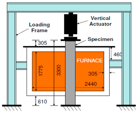 | [28] |
| Standard | ASTM E119 | ||||
| Duration of heating phase | 90 min and 120 min | ||||
| 4. | Column fire furnace | Size | Internal hot zone: 2 m × 1 m × 1 m | 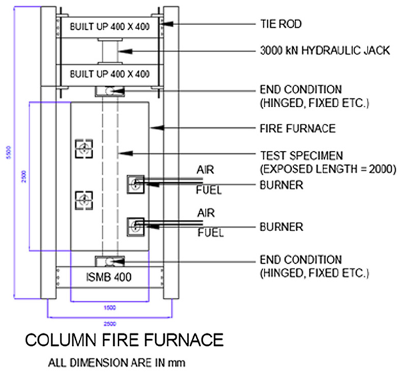 | [29] |
| 5. | Small-scale fireproof testing furnace | Fire curve follows | ISO 834 | 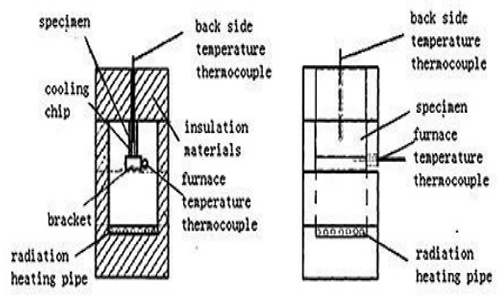 | [30] |
| 6. | Vulcan fire-resistance test furnace | Size | 0.5 m × 0.5 m × 0.5 m | 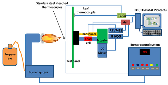 | [31] |
| Standard | BS 476 | ||||
| 7. | Large-scale furnace | Fire curve follows | ISO 834 | 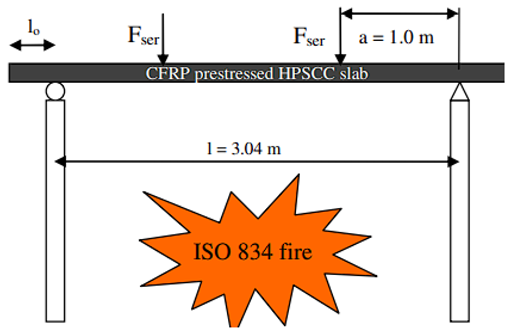 | [32] |
| 8. | Large-size furnace | Max furnace temp. | 1300 °C | 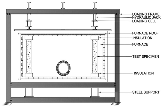 | [33] |
| 9. | Custom-designed fire-resistance test furnace | Fire curve follows | ISO 834 |  | [34] |
| 10. | Fire test furnace | Standard | CAN/ULC-S101-14 | 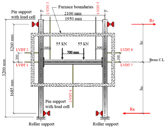 | [35] |
| 11. | Horizontal fire test furnace | Size | 5 m × 3 m | 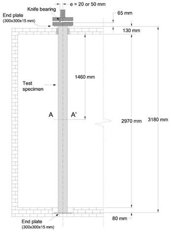 | [36] |
| Fire curve follows | ISO 834 | ||||
| 12. | Large-scale vertical fire-resistance test furnace | Size | Internal chamber: 3 m × 3 m × 1.3 m | 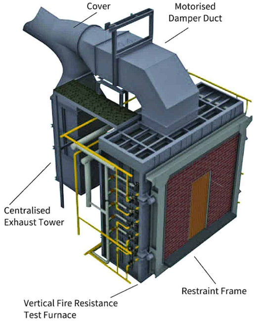 | [37] |
| Standard | BS476 Parts 20–24 EN1363 | ||||
| 13. | Horizontal fire-resistance test furnace | Size | Internal chamber: 3 m × 4 m × 1 m | 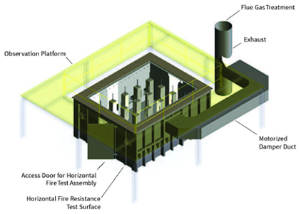 | [37] |
| Standards | BS476 Parts 20–24 EN1363 | ||||
| 14. | Indicative fire-resistance test furnace | Size | Internal chamber: 1 m × 1 m × 1 m, and 1.5 m × 1.5 m × 1.5 m |  | [39] |
| 15. | Large structural fire test furnace | Standards | AS1530.4, BS476 Parts 20–24, ISO 834, ISO 3008, ISO 3009, and ASTM E119 | 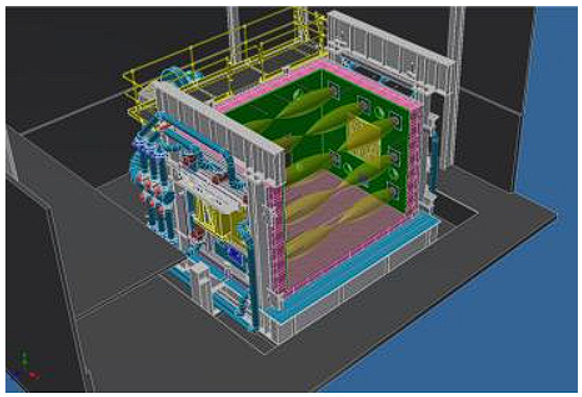 | [40] |
5. Non-Standard/Ad Hoc Fire-Resistance Testing Setup Used by Researchers
In general, the standard fire testing procedures are used to illustrate the response of building elements in fire. However, the simplified one element tests on isolated structural members subjected to unrealistic time–temperature curve have many limitations. Therefore, ad hoc non-standard fire tests, by means of real fire rather than standard fire, were introduced. Non-standard fire tests have identified many inadequacies in building behavior that could not have been detected through standard furnace tests. The main criticisms standard fire-resistance tests include: (1) standard temperature–time curve is substantially impractical and contradicts available knowledge of fire behavior; (2) the mandatory period of fire exposure in the standard fire test is open to disparagement on many basis and needs to be revisited; and (3) end condition and loading are not well defined in the standard test–and evidently cannot characterize the restraint continuity, membranes and redistribution actions in real structure. Thus, the use of knowledge-based analytical approaches should be promoted.
The literature on fire-resistance testing of construction elements is wide and authors frequently modify their experiments based on their requirements. This section summarizes studies selected based on uniqueness of their non-standard or modified standard testing procedures. Ramirez et al. conducted fire-resistance testing on cement mortars containing mineral wool recycled from construction and destruction waste. Fire-resistance was determined according to modified IS R-834 and UNE-EN 1361-1 (2012), UNE-EN 1363-2 (2000), and UNE-EN 1365-4 standards. A fire-resistance experiment was performed by following ISO TR-834 standard. The 40×40×160 mm specimens, Figure 11a, were directly exposed to flames accomplished a maximum temperature of 700 °C. The samples were positioned horizontally on a steel frame grill size of 1 m2, as shown in Figure 11b. The samples are positioned on the steel grill so that each compound has a sample in the innermost and intermediate area farthest from the fire. The fire was initiated by spraying pinewood with petrol for combustion [47]. The fire ignition method and maximum temperatures were adjusted in the study to suit their intended objective.
Stefan et al. directed a fire test on cementitious composites to measure the thermal performance, residual strength, and tendency of spalling based on ISO 834 fire testing standards. Blocks were positioned in a furnace and exposed to fire. The fire test was performed in a vertical test furnace, as shown in Figure 12. After a one-day cooling period, the heated blocks were noted and weighed another time and then tested in a hydraulic press. A two-pyramid failure mode was experienced. One face of the test specimen was heated for up to 120 min and then cooled for 1 day. After cooling, the thermal behavior and weight were determined. The heating of one face of the specimen may work well for certain fire situations, such as the ones considered in this study [48].
Shah et al. conducted a fire-resistance test on confined concrete columns. The testing furnace (Figure 13) was customized to develop the temperature shape as per the ISO 834. To monitor the four burners and the fire exposure, at least five viewpoints were available on furnace wall. The exterior size of the furnace was 2.5 × 1.5 × 1.5 m. The furnace had a central-opening square-plan size of 400 × 400 mm. The column length was 4 m, with an exposed length of 2 m. A hydraulic jack of 300-ton capacity was also involved in the loading frame for columns’ loading under compression to suit their requirements. The furnace was used to test the columns with different support conditions, including fixed and hinged and under concentric and eccentric loads [2].
Sarker et al. conducted a fire durability test on steel-reinforced fly-ash geopolymer concrete elements. The specimens, after 28 days of casting, were exposed to fire. Figure 14a presents a test panel placed in the furnace. One of the faces of the panel was exposed to fire, and the opposite side of the face remained at room temperature. This situation of heating is considered the most serious, as it causes differential temperatures between the unheated and heated faces. The controlled fire based on ISO 834 was recommended. The air temperatures inside the furnace and at 25 mm in depth from the unheated side of the test panel were recorded by inbuilt thermocouples sensor. A thermocouple was also inserted in samples at the time of casting. The furnace heating was terminated after two hours of specimen heating, and the samples were left to cool down at room temperature by leaving the door of the furnace open. After cooling down, the compression test was performed on the specimen by using a universal testing machine (Figure 14b) [49].
Vedrtnam et al. conducted an ad hoc fire-resistance test of transparent and tinted glass (see Figure 15). The apparatus was accumulated by a cast iron burner and a set of aluminum plates. One side of the setup was prepared with six vertical plates. Each plate was composed by two aluminum plates with a gap of 11 mm between them. The glass panels had sufficient space around them to enlarge freely at the time of the fire experience. These plates had regular end supports provided by the window frames [12].
Chen et al. conducted a fire-resistance test to measure the performance of recycled glass composites. A specially designed furnace (Figure 16) based on BS 476 part-22 was used to assess the integrity, residual strength, and thermal conductivity of test specimens. All samples were dried for 72 h at 80 °C before the fire test, and then the samples were fixed mechanically on the furnace face opening (size 315 × 165 mm). One face of the panel was bare to high temperatures. To avoid heat leakage between the panel specimen and the furnace, a thermal-insulation mat was provided. To measure the furnace temperature, S-type thermocouples were installed in the furnace. To measure the temperature rise of the unexposed side of the specimen, K-types (five in numbers) were installed on the unexposed side of the panel samples [50].
Maier et al. investigated the effect of concrete properties such as penetrability and ecological conditions (water content) on the spalling behavior of concrete exposed under the fire. An innovative two-compartment fire furnace (Figure 17), consisting of four main parts (combustion chamber, oil burner, temperature-control unit, and test chamber), was developed. The oil burner is located at the front wall of the furnace and provides the combustion compartment to reach temperatures up to 1400 °C. This compartment assists as a temperature tank and is coupled to the temperature-control unit. This unit permits programmed and precise control of heat flux into the (adjacent) test compartment (1400 × 500 × 400 mm3). The burner capacity and thermal flux were adjusted by using a temperature-control unit and K-type thermocouples, respectively [51].
Park et al. conducted an investigational study on fire sources for full-scale fire testing of a simple sprinkler system fitted in complexes. A sofa model was used to measure the effectiveness of fire-resistance performance of the sprinkler. The fire-resistance performance was compared to assess the fire-control capability the when water pressure was not sufficient [52]. Similarly, Lafrance et al. performed a large-scale fire-resistance test for wall assembly use in mid-rise buildings. In that study, a large-scale furnace test was performed to measure the fire endurance period for a light wood frame assembly. The wall furnace that was used in that test is shown in Figure 18 [53].
Sultan et al. compared the heat-exposure test results in full- and intermediate-scale fire-resistance test furnaces. The effects of furnace orientation and furnace size on the fire exposure were discussed. The results determined that the heat exposure in the intermediate-scale furnace is higher than that of the full-scale fire-resistance testing furnace. The full-scale and intermediate-scale floor testing furnaces are shown in Figure 19a,b [54].
Nassif et al. presented the experimental observations and outcomes of a full-scale fire-resistance test on a partition wall. The partition wall was built within a concrete frame and exposed to the standard fire test. The partition wall was made with C-section steel studs, with gypsum boards fixed on both sides, and the wall craters were filled with rock wool insulation. It was observed that the full-scale fire-resistance test gives detailed thermal profiling throughout the partition wall. The setup for the large-scale fire-resistance test of the partition wall utilized in the study is shown in Figure 20 [55].
Hidalgo et al. presented an investigational study considering full-scale open-floor-plan enclosure fires. In the research, a large-scale investigational sequence was assumed to create a complete data set to illustrate fire in large open-plan spaces, typical of tall buildings and contemporary infrastructure [56]. Bisby et al. prepared a review covering the non-standard fire-resistance testing methods used by researchers to characterize the response of structural material in fire [7]. Gale et al. conferred the backgrounds of the standard fire-resistance test, the boundaries within the fire testing or design, the difficulties of the results of the real fire in buildings, and the consequential research gap that currently exist [57]. Zhang et al. presented a scheme with an ASTM E 119 fire environment in a large section (size 10 m wide, 7 m depth, and 3.8 m height), using the designed fire constraints, including opening condition (size and configuration) and heat release rate (HRR) curve to conduct a full-scale test. The mean upper layer of the gas-temperature curve followed the E119 fire curve. The highest variance among the E119 and the measured curve towards the end of the test was around 70 °C (7%). The investigation specifies that, through proper control and design, the temperature–time curve for the standard fire testing may be approximated in a real section [58].
Rodrigues et al. reported the behavior of square and circular reinforced-concrete columns with restrained thermal elongation exposed to fire. The spalling phenomenon was observed from the fire test results in both columns. The restraining level of the reinforced-concrete column against thermal elongation may not affect the performance of the columns and is irrelevant to their fire resistance. The experimental fire-resistance-test setup on columns is shown in Figure 21 [59].
Similarly, Magarabooshanam et al. investigated the load-bearing performance of double-stud light-gauge steel-frame walls exposed to fire. The full-scale fire-test setup (Figure 22) was developed to predict the failure times of double-stud light-gauge-steel-frame walls in fire, using the direct strength method. The results revealed that, in the double-stud light-gauge-steel-frame walls, the fire performance was enhanced because of the unique heat-transfer mechanism [60].
Researchers and regulating communities have confronted several problems in regard to characterizing building and construction elements with standard fire-resistance tests. Thus, large-scale fire-resistance testing has experienced momentum compared to standard fire-resistance testing. The non-standard fire-resistance test has been performed prominently during the last three decades to address critical aspects, as discussed before, during actual fires; in general, these critical aspects could not have been identified by the standard fire-resistance test. Non-standard fire-resistance tests of actual fire in real construction buildings are listed in Table 9.
6. Concluding Remarks
This article offers a comprehensive review and comparison of the fire-resistance testing standards suggested by the regulatory bodies of different countries, such as the USA, Britain, India, Japan, Australia, and China, as well as Europe. Moreover, the chronological order of the historical development of fire-resistance testing procedures was mentioned for the different fire testing standards developed by different countries. The detailed summary of ASTM, Australian, British, Chinese, DIN, European, Indian, ISO, and Japanese fire-resistance testing standard given in the article should be useful for researchers for designing their experiments. This review reflected that the Indian fire-resistance testing standard by also following the old method of British fire testing standard (BS 476 part 8), which needs to be updated according to BS 476 part 20 to 23. The review concluded that most of the country follows the British fire testing standard because it has separately discussed the guidelines for every traditional construction material. The consideration of fire-resistance testing requirements for advanced engineering materials in testing standards is advocated by the present review.
In reality, the fire location, its intensity, and corresponding scenarios vary significantly, and standard tests for isolated structural members may not efficiently portray the realistic fire scenarios. Thus, researchers have utilized a variety of specialized setups and full-scale non-standard fire tests that fulfil their research objectives. This article includes a summary of selected full-scale, ad hoc, and specialized setups reported in the literature. Additionally, all fire-resistance testing standards are laboratory-based tests and are performed under specified conditions through which it is hard to determine the most accurate fire-resistance of construction elements because of the unpredictable nature of real fire. This review highlights the requirement of periodic updates of standards for improving the reliability of fire-resistance testing results.
Author Contributions
Conceptualization, A.V. and S.C.; methodology, A.V.; formal analysis, A.V.; investigation, S.C., A.V. and S.C.; resources, A.V. and S.C.; data curation, S.C., K.K. and A.V.; writing—original draft preparation, S.C. and A.V.; writing—review and editing, M.A.Y. and A.V.; G.B., M.T.P. visualization, A.V.; supervision, M.A.Y. and A.V., G.B., M.T.P.; project administration, M.T.P., M.A.Y. and A.V.; funding acquisition, M.T.P., M.A.Y. and A.V. All authors have read and agreed to the published version of the manuscript.
Funding
This project received funding from the European Union’s Horizon 2020 Research and Innovation Programme under the Marie Skłodowska-Curie Grant Agreement No 945478 (SASPRO2). The content of this article does not reflect the official opinion of the European Union. Responsibility for the information and views expressed herein lies entirely with the author(s).
Institutional Review Board Statement
Not applicable.
Informed Consent Statement
Not applicable.
Data Availability Statement
Not applicable.
Acknowledgments
The administrative support of SASPRO2 team is appreciated.
Conflicts of Interest
The authors declare no conflict of interest.
References
- India-Risk-Survey-2017-Report. Available online: https://ficci.in/Sedocument/20416/India-Risk-Survey-2017-Report.pdf (accessed on 14 July 2022).
- India-Risk-Survey-2018. Available online: https://ficci.in/Sedocument/20450/India%20Risk%20Survey%20-%202018.pdf (accessed on 14 July 2022).
- Ahrens, M. Fire Loss in the United States during 2020. Available online: https://www.maine.gov/dps/fmo/sites/maine.gov.dps.fmo/files/inline-files/Fire%20Loss%20in%20the%20US%20during%202020.pdf (accessed on 14 July 2022).
- Beyler, C.; Beitel, J.; Iwankiw, N.; Lattimer, B. Fire Resistance Testing for Performance-Based Fire Design of Buildings; Final Report, NIST GCR 07-910; National Institute of Standards and Technology, U.S. Department of Commerce: Washington, DC, USA, 2007.
- Babrauskas, V.; Williamson, R.B. The historical basis of fire resistance testing—Part I. Fire Technol. 1978, 14, 184–194. [Google Scholar] [CrossRef]
- Babrauskas, V.; Williamson, R.B. The historical basis of fire resistance testing—Part II. Fire Technol. 1978, 14, 304–316. [Google Scholar] [CrossRef]
- Bisby, L.; Gales, J.; Maluk, C. A contemporary review of large-scale non-standard structural fire testing. Fire Sci. Rev. 2013, 2, 1. [Google Scholar] [CrossRef] [Green Version]
- Roszkowski, P.; Kimbar, G. Full-scale external fire test of free-standing steel silo. Fire Saf. J. 2021, 120, 103123. [Google Scholar] [CrossRef]
- Jiang, S.; Zhu, S.; Guo, X.; Li, Z. Full-scale fire tests on steel roof truss structures. J. Constr. Steel Res. 2020, 169, 106025. [Google Scholar] [CrossRef]
- Shah, A.H.; Sharma, U.K.; Bhargava, P. Outcomes of a major research on full scale testing of RC frames in post earthquake fire. Constr. Build. Mater. 2017, 155, 1224–1241. [Google Scholar] [CrossRef]
- Zheng, W.Z.; Hou, X.M.; Shi, D.S.; Xu, M.X. Experimental study on concrete spalling in prestressed slabs subjected to fire. Fire Saf. J. 2010, 45, 283–297. [Google Scholar] [CrossRef]
- Vedrtnam, A.; Bedon, C.; Youssef, M.A.; Wamiq, M.; Sabsabi, A.; Chaturvedi, S. Experimental and numerical structural assessment of transparent and tinted glass during fire exposure. Constr. Build. Mater. 2020, 250, 118918. [Google Scholar] [CrossRef]
- ASTM E119: Standard Test Methods for Fire Tests of Building Construction and Materials. Available online: https://technokontrol.com/pdf/walls_astm.e119.2000.pdf (accessed on 28 December 2021).
- AS 1530.4-2005 Methods for Fire Tests on Building Materials, Components and Structures. Part 4: Fire-Resistance Test of Elements of Construction | Building CodeHub. Available online: https://codehub.building.govt.nz/resources/as-1530-4-2005/ (accessed on 2 November 2021).
- British Standard 476 Fire Tests: Firesafe.org.uk. Available online: https://www.firesafe.org.uk/british-standard-476-fire-tests/ (accessed on 2 November 2021).
- IS 3809; Fire Resistance Test for Structures. Bureau of Indian Standards: New Delhi, India, 1979. Available online: https://ia800900.us.archive.org/9/items/gov.in.is.3809.1979/is.3809.1979.pdf (accessed on 28 December 2021).
- Fire Resistance Test to Building Construction—CASfire. Available online: http://www.casfire.cn/en/?stm_works=fire-test-to-building-material (accessed on 28 December 2021).
- DIN4102-1: Fire Test to Building Material–Classification_Building Material_Fire Test Center_FireTC.net. Available online: http://www.firetc.net/firetesting/show.php?itemid=663 (accessed on 2 November 2021).
- Japan Standards Association (JSA). JIS A 1304: Method of Fire Resistance Test for Structural Parts of Buildings. 1994. Available online: http://archive.org/details/jis.a.1304.e.1994 (accessed on 28 December 2021).
- EN 1363-1 Fire Resistance Test_Test Method_Fire Test Center_FireTC.net. Available online: http://firetc.net/firetesting/show.php?itemid=720 (accessed on 2 November 2021).
- ISO 834-13:2019. Available online: https://www.iso.org/standard/66439.html (accessed on 28 December 2021).
- Fire Resistance Test Furnace, Fire Resistance Test Furnace & Fire Test Apparatus—CMTS. Available online: https://www.cmtsproduct.com/fire-resistance-test-furnace/ (accessed on 2 November 2021).
- Chow, W.K. Review on fire safety management and application to Hong Kong. Int. J. Eng. Perform.-Based Fire Codes 2001, 3, 52–58. [Google Scholar]
- Fire Performance and Flammability of Materials, Specifying Fielders. Available online: https://specifying.fielders.com.au/roofing-walling/design-data/fire-performance-and-flammability-of-materials/ (accessed on 12 December 2021).
- Dumont, F.; Wellens, E.; Gernay, T.; Franssen, J.-M. Loadbearing capacity criteria in fire resistance testing. Mater. Struct. 2016, 49, 4565–4581. [Google Scholar] [CrossRef] [Green Version]
- Kai, Y.; Yao, Z.; Hao, C.; Lili, F.; Zhang, X. Postfire Safety Investigation on Prestressed RPC Beams after Exposure to Elevated Temperatures. Adv. Mater. Sci. Eng. 2020, 2020, e7837418. [Google Scholar] [CrossRef]
- Imani, R.; Mosqueda, G.; Bruneau, M. Experimental Study on Post-Earthquake Fire Resistance of Ductile Concrete-Filled Double-Skin Tube Columns. J. Struct. Eng. 2014, 141, 04014192. [Google Scholar] [CrossRef] [Green Version]
- Kodur, V.; Hibner, D.; Agrawal, A. Residual response of reinforced concrete columns exposed to design fires. Procedia Eng. 2017, 210, 574–581. [Google Scholar] [CrossRef]
- Shah, A.H.; Sharma, U.K. Fire resistance and spalling performance of confined concrete columns. Constr. Build. Mater. 2017, 156, 161–174. [Google Scholar] [CrossRef]
- Ji, W.; Hua, S.; Miao, Z.; Zhen, C. Study and Prediction for the Fire Resistance of Acid Corroded Intumescent Coating. Procedia Eng. 2014, 84, 524–534. [Google Scholar] [CrossRef] [Green Version]
- Cutter, P.A.; Shenoi, R.; Phillips, H.; Moy, S.S.J. A new small scale fire resistance test method for composite materials. In Proceedings of the International Conferences on Composite Materials (ICCM), Edinburgh, UK, 27–31 July 2009. [Google Scholar]
- Maluk, C.; Terrasi, G.; Bisby, L.; Stutz, A.; Hugi, E. Experimental fire Behaviour of Thin-walled CFRP Pretensioned High Strength Concrete Slabs under Service Load. In Proceedings of the 7th International Conference on FRP Composites in Civil Engineering (CICE), Vancouver, BC, Canada, 20–22 August 2014. [Google Scholar]
- Nair, A.; Salem, S. Experimental Determination of the Residual Compressive Strength of Concrete Columns Subjected to Different Fire Durations and Load Ratios. J. Struct. Fire Eng. 2020, 11, 529–543. [Google Scholar] [CrossRef]
- Lineham, S.; Thomson, D.; Bartlett, A.; Bisby, L.; Hadden, R. Structural response of fire-exposed cross-laminated timber beams under sustained loads. Fire Saf. J. 2016, 85, 23–34. [Google Scholar] [CrossRef]
- Salem, S. Parametric Study on Load Ratio Effect on the Flexural Bending Behaviour of Axially-restrained HSS Steel Beams Subjected to Fire. J. Struct. Fire Eng. 2018, 9, 342–360. [Google Scholar] [CrossRef]
- Moliner, V.; Espinós, A.; Romero, M.; Hospitaler, A. Fire behavior of eccentrically loaded slender high strength concrete-filled tubular columns. J. Construct. Steel Res. 2013, 83, 137. [Google Scholar] [CrossRef]
- Large Scale Vertical Fire Resistance Test Furnace—Fire Testing Technology. Available online: https://www.cmtsproduct.com/vertical-fire-resistance-test-furnace/ (accessed on 19 January 2022).
- Horizontal Fire Resistance Test Furnace—Fire Testing Technology. Available online: https://www.fire-testing.com/horizontal-fire-resistance-test-furnace/ (accessed on 19 January 2022).
- Indicative Fire Resistance Test Furnace—Fire Testing Technology. Available online: https://www.fire-testing.com/indicative-fire-resistance-test-furnace/ (accessed on 19 January 2022).
- Fire Test Facilities, Victoria University, Australia. Available online: https://www.vu.edu.au/research/researching-at-vu/laboratories-facilities/fire-test-facilities (accessed on 14 October 2022).
- Wickström, U. The plate thermometer—A simple instrument for reaching harmonized fire resistance tests. Fire Technol. 1994, 30, 195–208. [Google Scholar] [CrossRef]
- Han, H.-S.; Yun, H.-S.; Hwang, C.-H. Calibration of the plate thermometer for measuring heat flux using a conical heater. J. Mech. Sci. Technol. 2019, 33, 3563–3569. [Google Scholar] [CrossRef]
- Ingason, H.; Wickström, U. Measuring incident radiant heat flux using the plate thermometer. Fire Saf. J. 2007, 42, 161–166. [Google Scholar] [CrossRef]
- Sultan, M.A. Fire Resistance Furnace Temperature Measurements: Plate Thermometers vs. Shielded Thermocouples. Fire Technol. 2006, 42, 253–267. [Google Scholar] [CrossRef] [Green Version]
- Ditch, B. Evaluating Pool Fire Severity and the Cooling Effect of Local Water Spray Using a Continuous Plate Thermometer. Fire Saf. Sci. 2011, 10, 133–144. [Google Scholar] [CrossRef]
- Sultan, M. Comparisons of Temperature and Heat Flux in Furnaces Controlled by Different Types of Temperature Sensors. J. ASTM Int. 2010, 7, 44–62. [Google Scholar] [CrossRef] [Green Version]
- Ramírez, C.P.; Barriguete, A.V.; Somolinos, R.S.; del Río Merino, M.; Atanes Sánchez, E. Analysis of fire resistance of cement mortars with mineral wool from recycling. Constr. Build. Mater. 2020, 265, 120349. [Google Scholar] [CrossRef]
- Štefan, R.; Foglar, M.; Fládr, J.; Horníková, K.; Holan, J. Thermal, spalling, and mechanical behaviour of various types of cementitious composites exposed to fire: Experimental and numerical analysis. Constr. Build. Mater. 2020, 262, 119676. [Google Scholar] [CrossRef]
- Sarker, P.K.; Mcbeath, S. Fire endurance of steel reinforced fly ash geopolymer concrete elements. Constr. Build. Mater. 2015, 90, 91–98. [Google Scholar] [CrossRef]
- Chen, B.; Zhu, H.; Li, B.; Sham, M.; Li, Z. Study on the fire resistance performance of cementitious composites containing recycled glass cullets (RGCs). Constr. Build. Mater. 2020, 242, 117992. [Google Scholar] [CrossRef]
- Maier, M.; Zeiml, M.; Lackner, R. On the effect of pore-space properties and water saturation on explosive spalling of fire-loaded concrete. Constr. Build. Mater. 2020, 231, 117150. [Google Scholar] [CrossRef]
- Park, J.; Kwark, J. Experimental Study on Fire Sources for Full-Scale Fire Testing of Simple Sprinkler Systems Installed in Multiplexes. Fire 2021, 4, 8. [Google Scholar] [CrossRef]
- Lafrance, P.-S.; Berzins, R.; Leroux, P.; Su, J.Z.; Lougheed, G.D. Full-Scale Standard Fire Resistance Test of a Wall Assembly for Use in Lower Storeys of Mid-Rise Buildings: Report to Research Consortium for Wood and Wood-Hybrid Mid-Rise Buildings; National Research Council of Canada: Ottawa, ON, Canada, 2014. [CrossRef]
- Sultan, M.; Benichou, N.; Min, B. Heat exposure in fire resistance furnaces: Full-scale vs. intermediate-scale. In Proceedings of the Fire and Materials 2003 International Conference, San Francisco, CA, USA, 27–29 January 2003; pp. 43–53. [Google Scholar]
- Nassif, A.Y.; Yoshitake, I.; Allam, A. Full-scale fire testing and numerical modelling of the transient thermo-mechanical behaviour of steel-stud gypsum board partition walls. Constr. Build. Mater. 2014, 59, 51–61. [Google Scholar] [CrossRef]
- Hidalgo, J.P.; Cowlard, A.; Abecassis-Empis, C.; Maluk, C.; Majdalani, A.H.; Kahrmann, S.; Hilditch, R.; Krajcovic, M.; Torero, J.L. An experimental study of full-scale open floor plan enclosure fires. Fire Saf. J. 2017, 89, 22–40. [Google Scholar] [CrossRef]
- Gales, J.; Maluk, C.; Bisby, L. Structural Fire Testing—Where are we, how did we get here, and where are we going? In Proceedings of the 15th International Conference on Experimental Mechanics (ICEM 15), Porto, Portugal, 22–27 July 2012. [Google Scholar]
- Zhang, C.; Grosshandler, W.; Sauca, A.; Choe, L. Design of an ASTM E119 fire environment in a large compartment. Fire Technol. 2019, 56, 1155–1177. [Google Scholar] [CrossRef] [PubMed]
- Rodrigues, J.P.; Laím, L.; Gonçalves, M. Fire resistance of square and circular cross-section concrete columns. In Proceedings of the 7th International Conference on Structures in Fire, Zurich, Switzerland, 6–8 June 2012. [Google Scholar]
- Magarabooshanam, H.; Ariyanayagam, A.; Mahendran, M. Behaviour of load bearing double stud LSF walls in fire. Fire Saf. J. 2019, 107, 15–28. [Google Scholar] [CrossRef]
Figure 1.
Fire-resistance-test standards for building elements and structures.

Figure 2.
Test furnaces: (a) horizontal, (b) vertical, (c) hydraulic, (d) indicative, and (e) miniature.
Figure 2.
Test furnaces: (a) horizontal, (b) vertical, (c) hydraulic, (d) indicative, and (e) miniature.
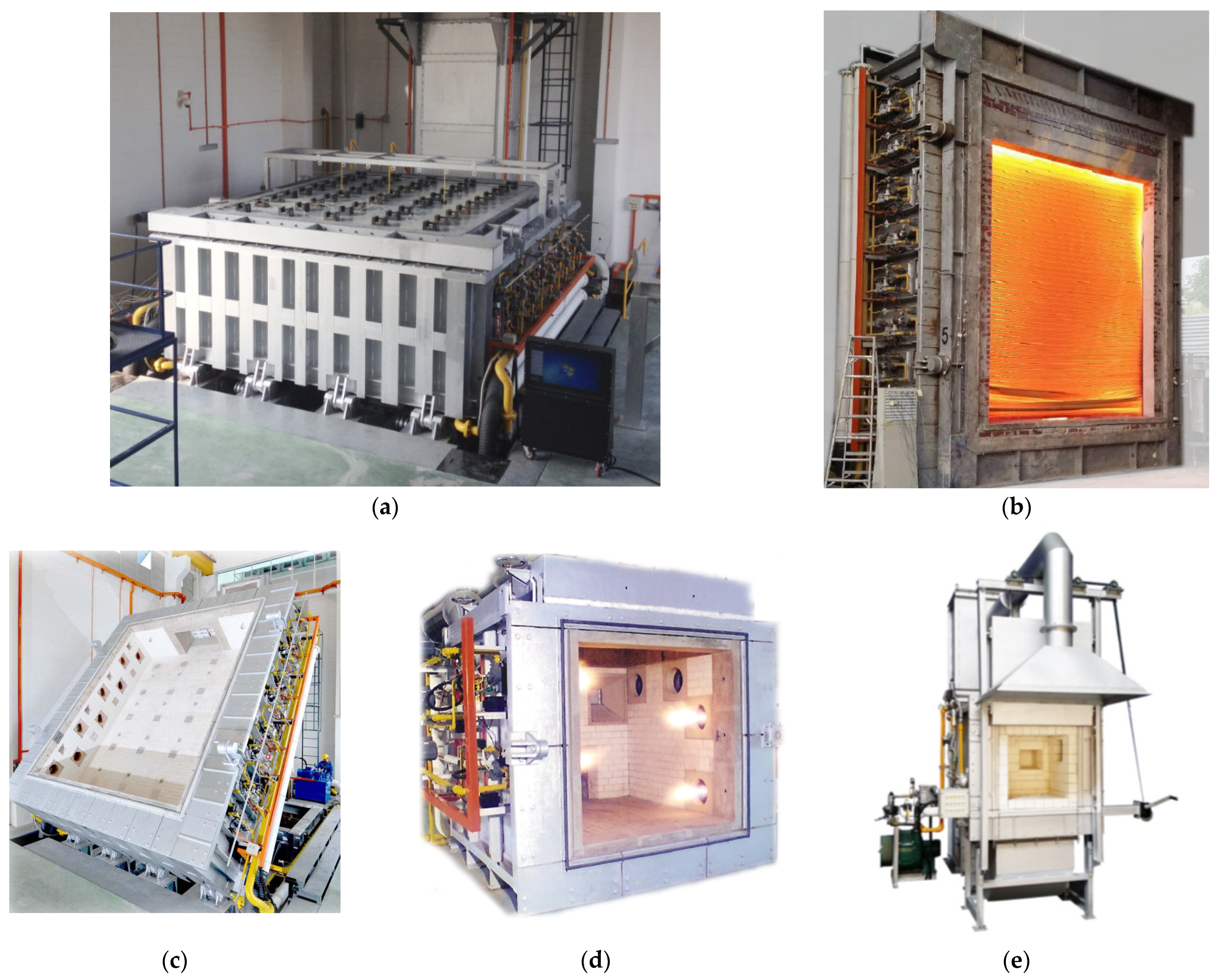
Figure 3.
Pressure and heating applied on a test sample according to BS 476.
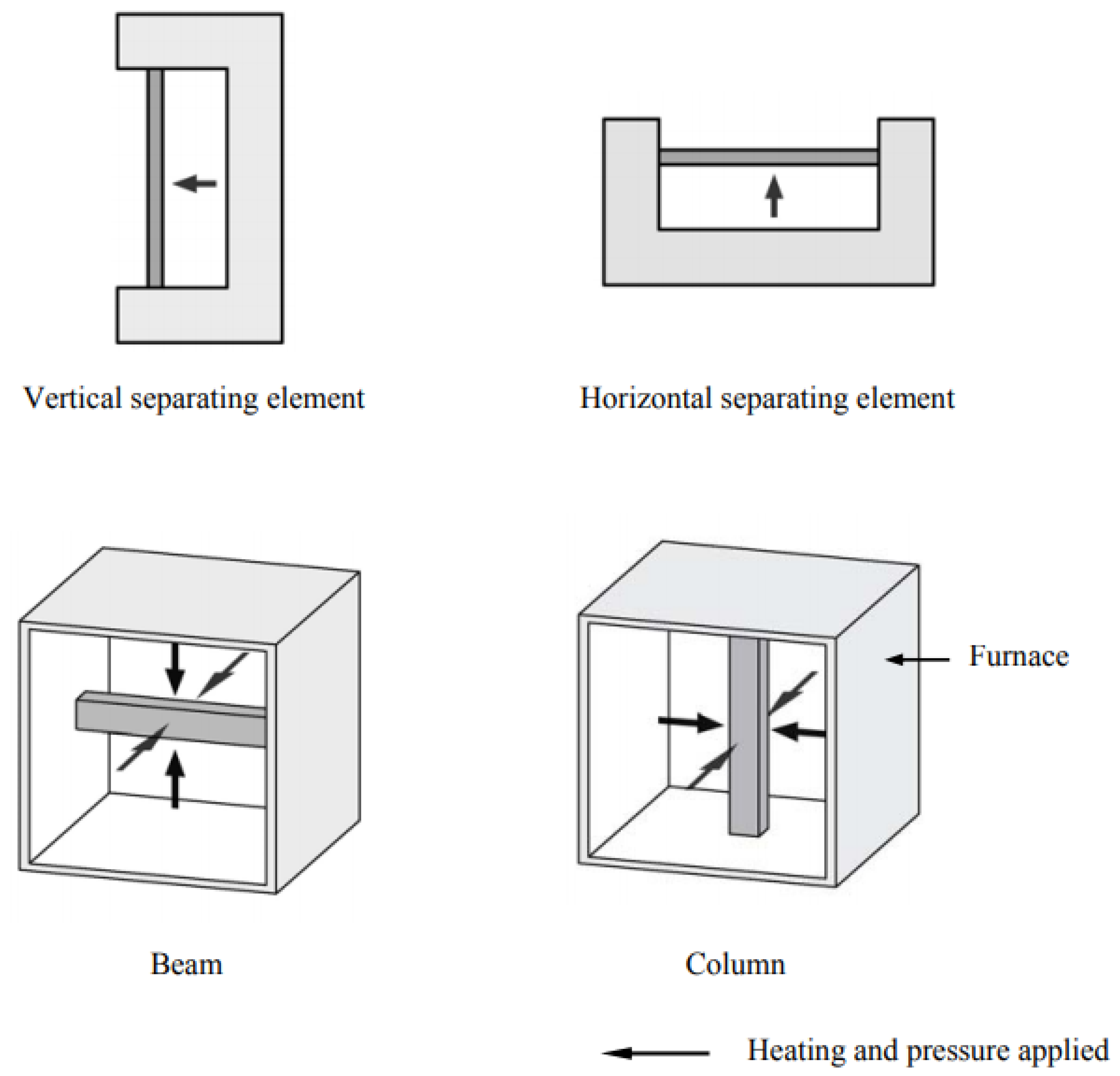
Figure 4.
Comparison of time/temperature curves of different fire-resistance standards.

Figure 5.
Restraints for load-bearing walls: (a) 2D, (b) 3D, and (c) section.
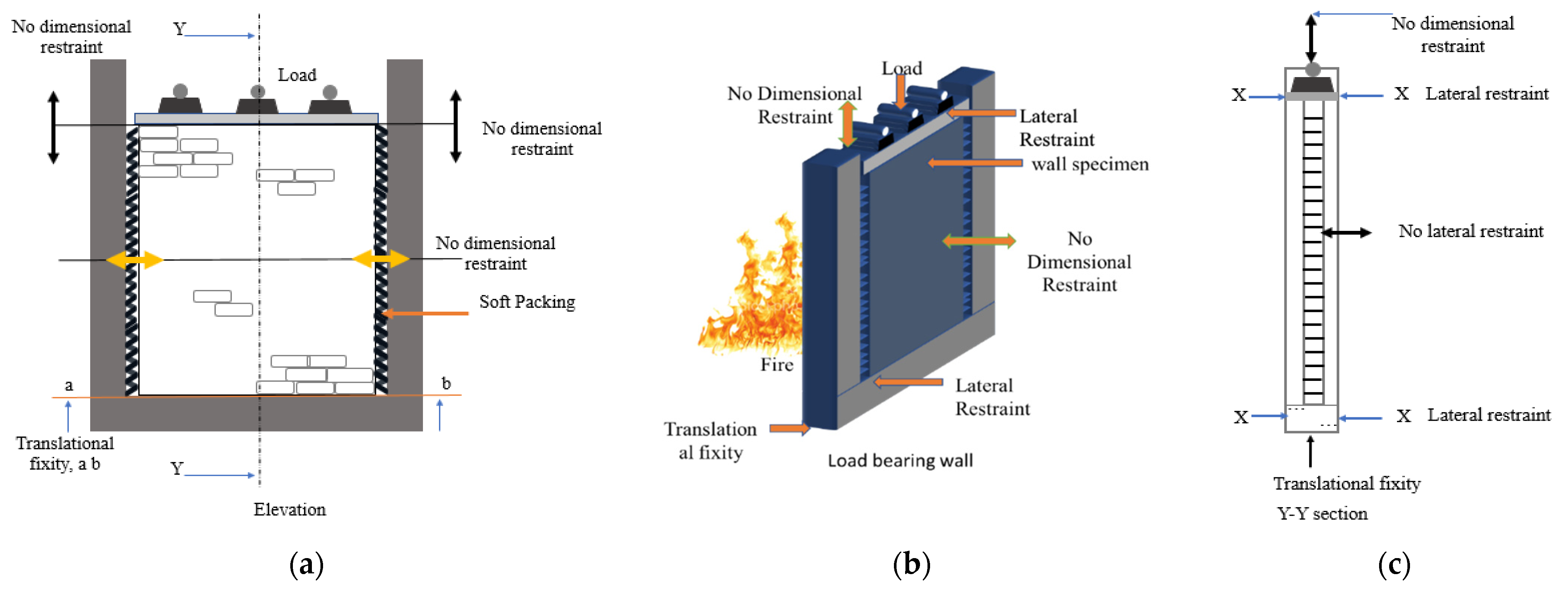
Figure 6.
Restraints for non-load-bearing walls: (a) 2D, (b) 3D, and (c) section.

Figure 7.
Restraints for floors: (a) 2D, (b) section, (c) 3D, and (d) rotational fixity.
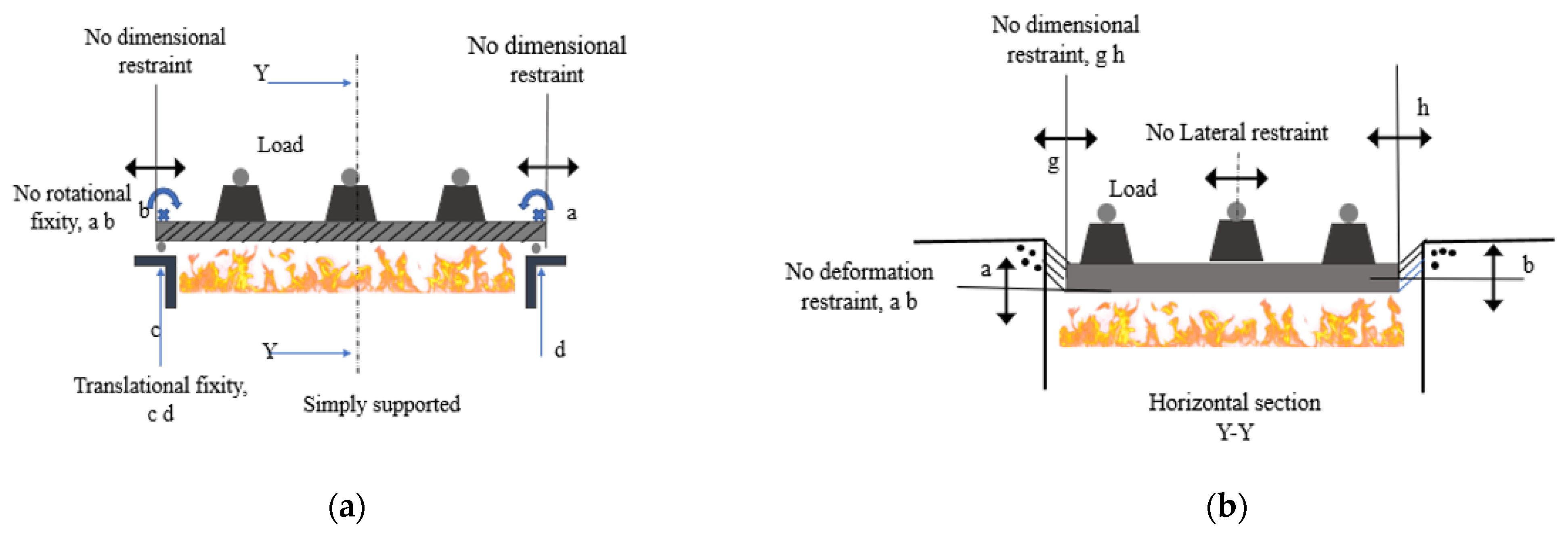

Figure 8.
Restraints for columns pinned at one end: (a) 2D, (b) 3D, and (c) section.
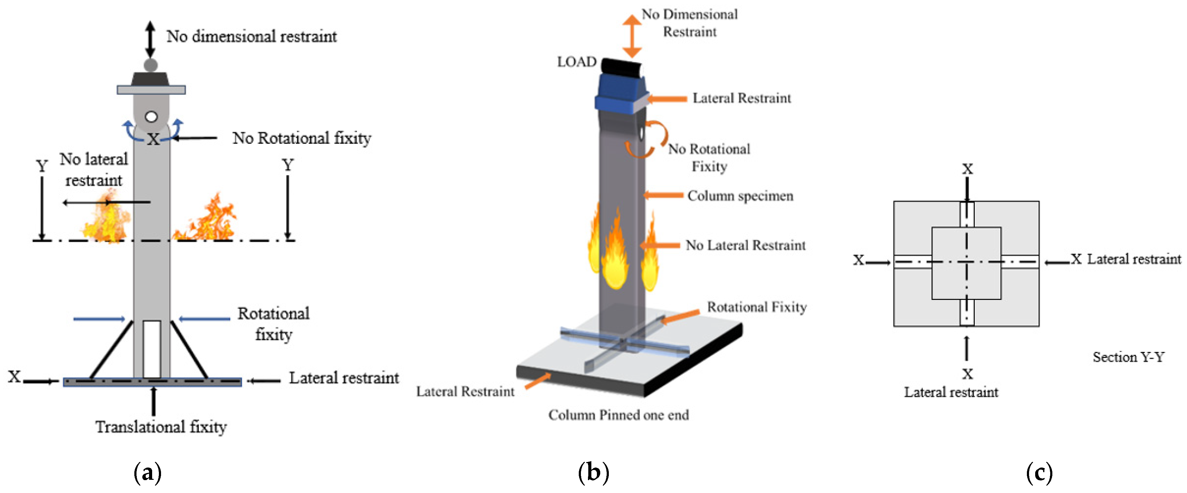
Figure 9.
Restraints for beams: (a) 2D, (b) section, and (c) beam fixed at one end.

Figure 10.
Fire-resistance level.
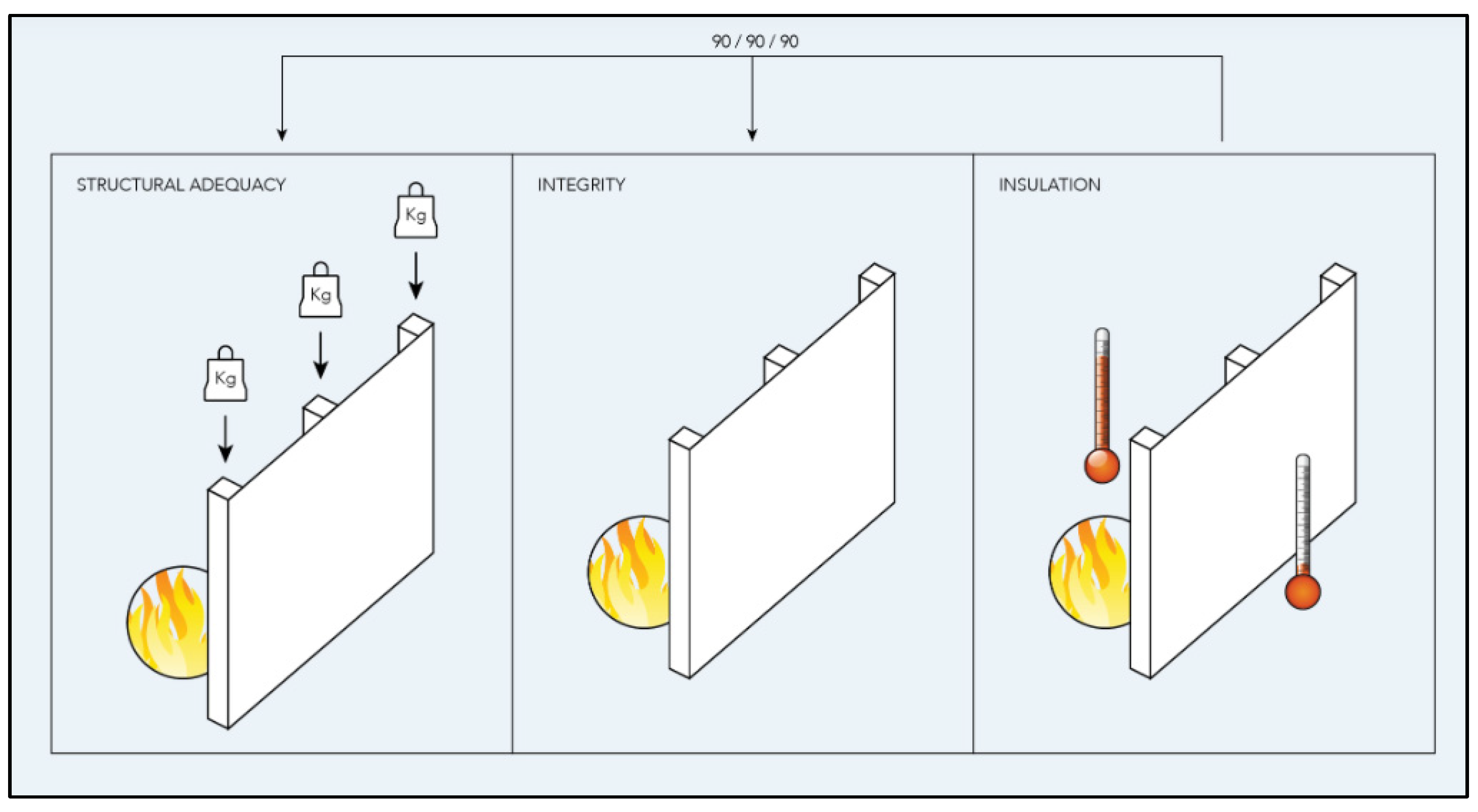
Figure 11.
Fire-resistance of cement mortars: (a) specimens and (b) fire test.
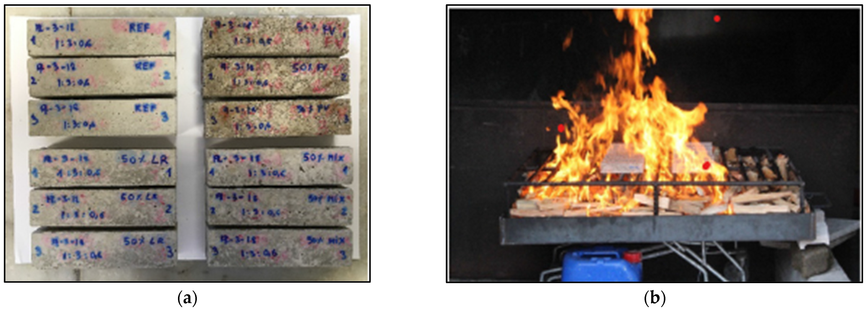
Figure 12.
Fire test on cementitious composites: (a) furnace, and (b) heating side.

Figure 13.
Confined-concrete-column fire-resistance test.

Figure 14.
Fire-resistance testing on steel-reinforced fly-ash geopolymer concrete: (a) concrete test panel and (b) post-fire compression test setup.
Figure 14.
Fire-resistance testing on steel-reinforced fly-ash geopolymer concrete: (a) concrete test panel and (b) post-fire compression test setup.

Figure 15.
Specialized fire test setup (1) burner, (2) box lateral wall, (3) lateral wall, (4) black wall, (5) top cover and slots. and (6) samples.
Figure 15.
Specialized fire test setup (1) burner, (2) box lateral wall, (3) lateral wall, (4) black wall, (5) top cover and slots. and (6) samples.

Figure 16.
Specially designed furnace and specimen installation for lab-scale fire test.
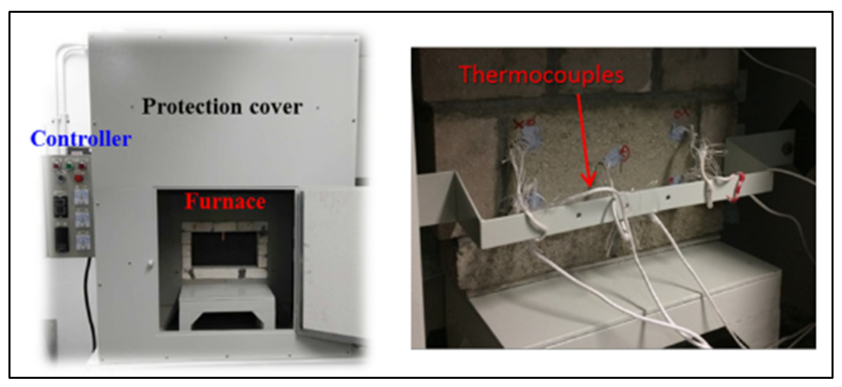
Figure 17.
Two-chamber fire furnace (dimensions in cm).
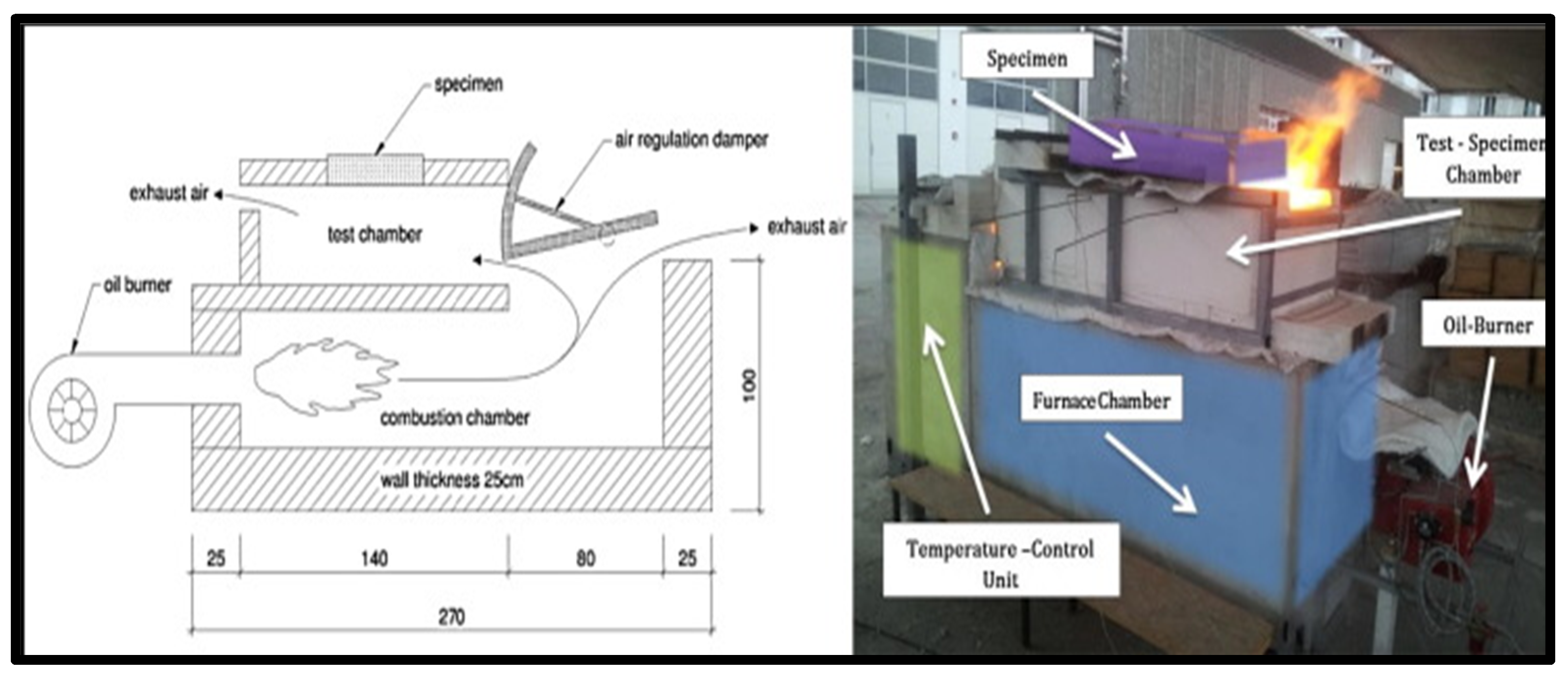
Figure 18.
Wall furnace used for full-scale fire-resistance test.
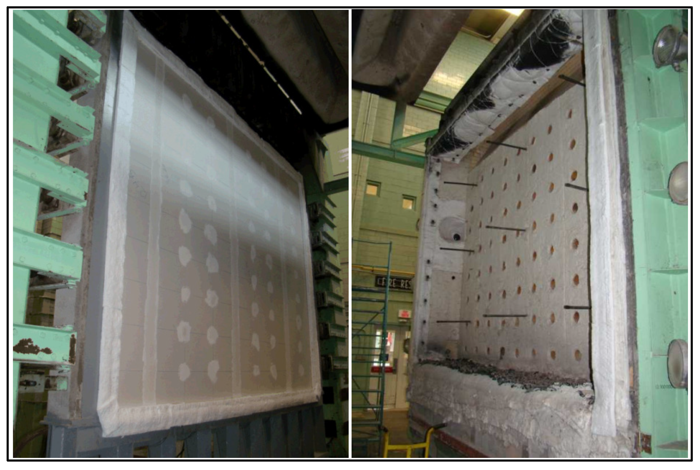
Figure 19.
(a) Full-scale floor furnace and (b) intermediate-scale floor furnace.
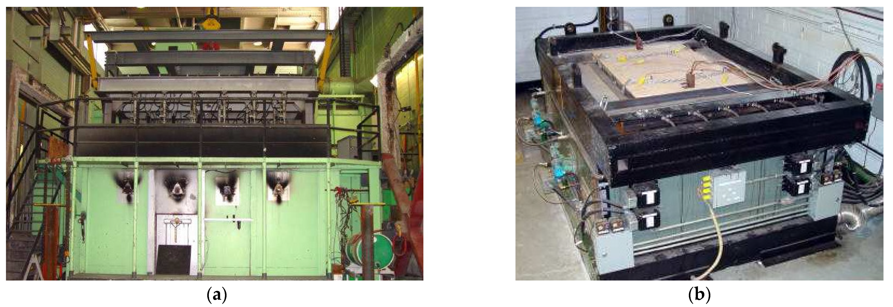
Figure 20.
The full-scale standard fire-resistance-test setup of the partition wall.
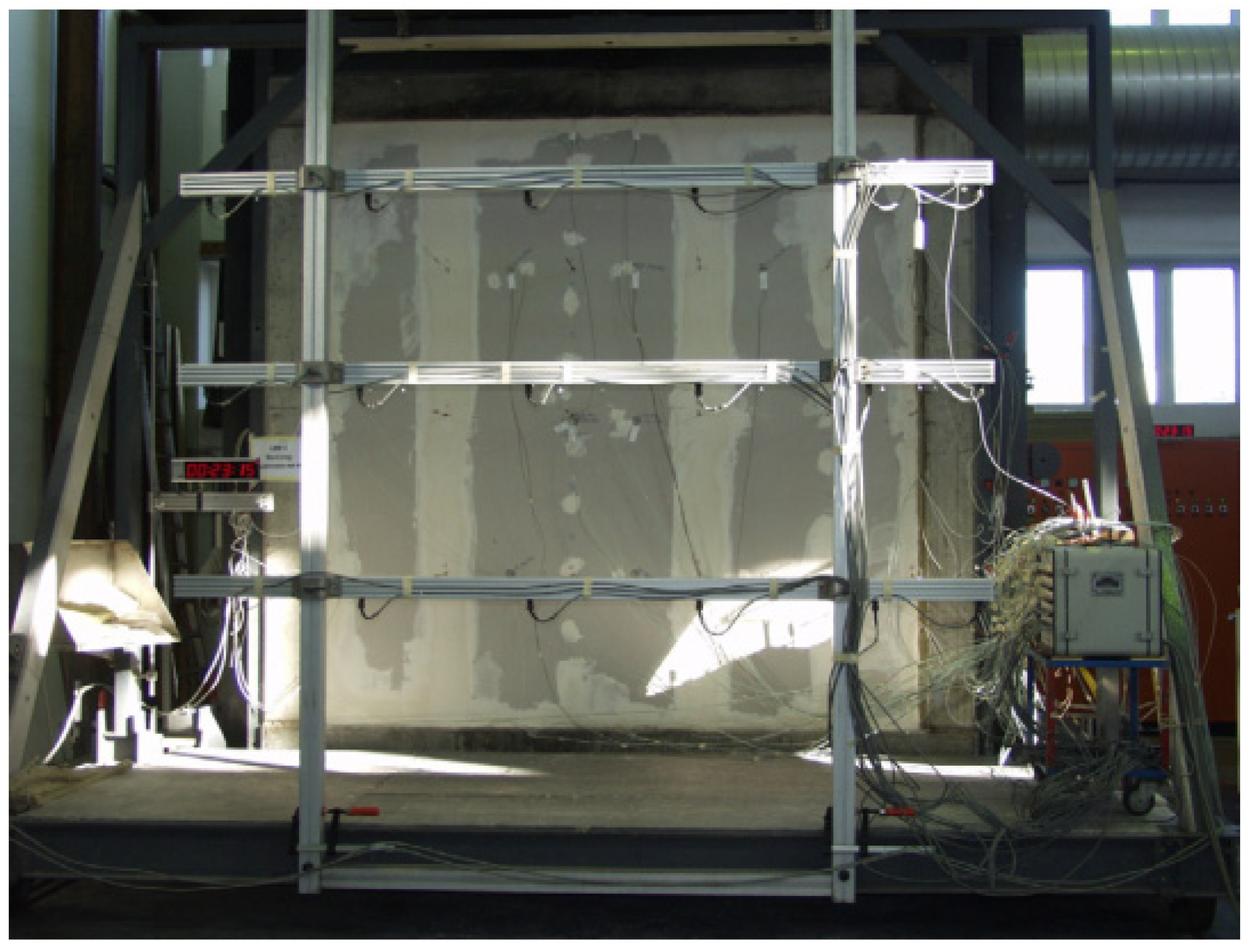
Figure 21.
The fire-resistance-test setup on columns.
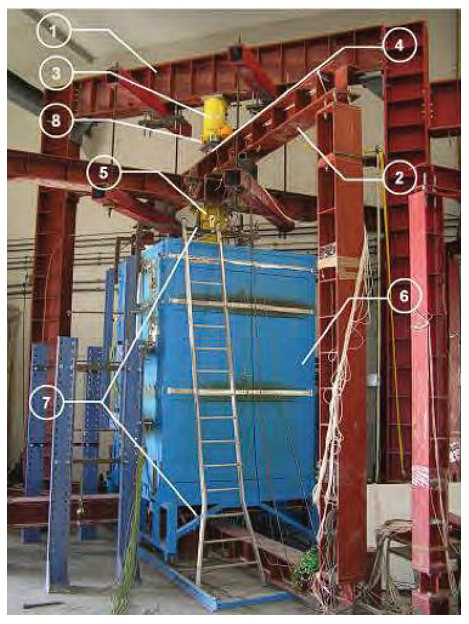
Figure 22.
The full-scale fire-resistance-test setup: (a) furnace, and (b) test panel.
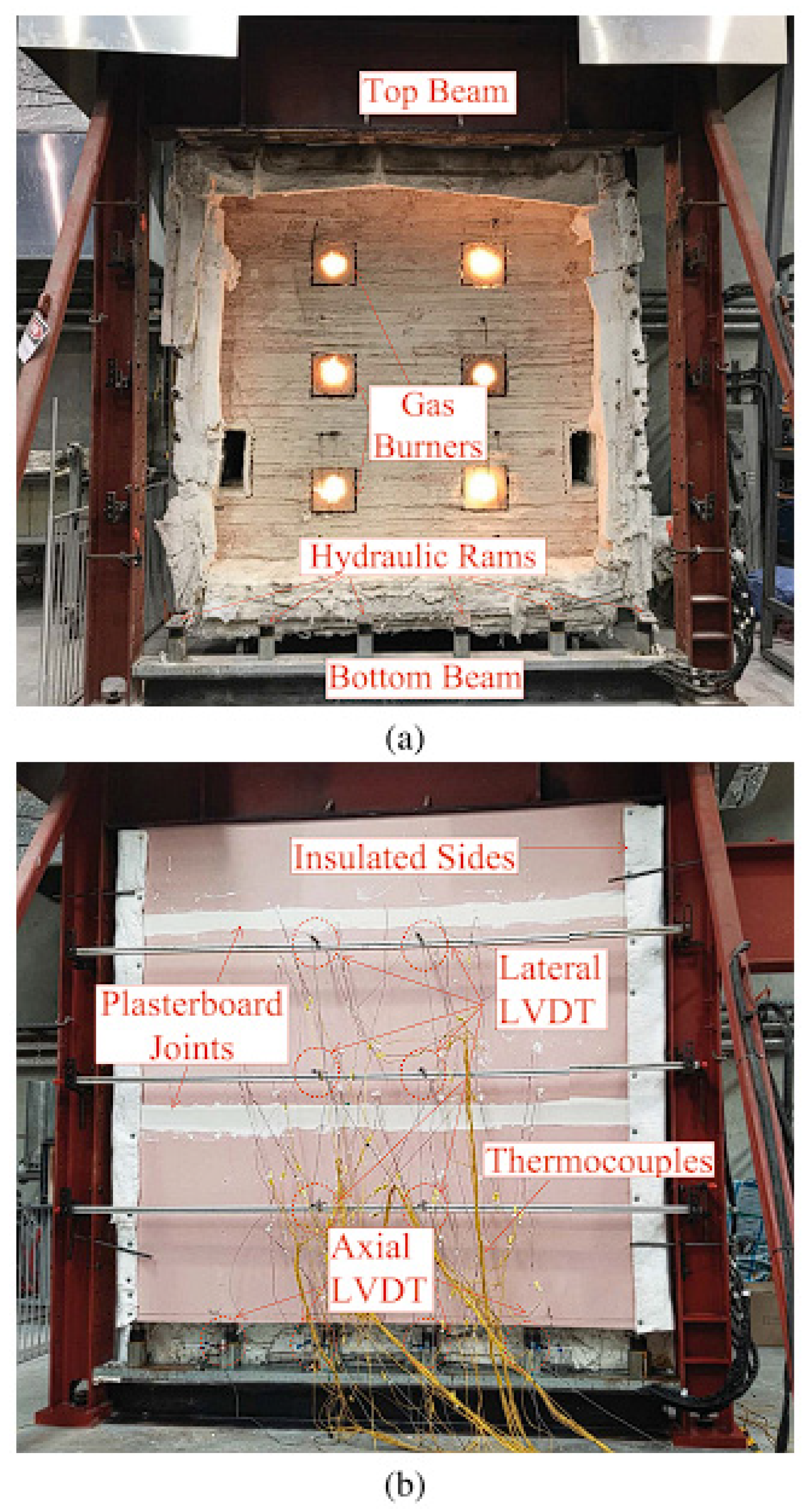
Table 1.
Historical development of fire-resistance procedures.
| Year | Development [5,6] |
|---|---|
| 1880 | Start of fire tests in Europe. |
| 1884 | Establish fire-test facility in Berlin and fire tests of columns in Germany and Austria. |
| 1890 | Start of fire tests in the US. |
| 1891 | Fire test of the first wall in Germany. |
| 1891 | Floor fire test in St. Louis. |
| 1892 | Door fire test in Berlin. |
| 1893 | Wall fire test in Vienna and fire tests on floors, doors, and windows in Berlin. |
| 1894 | Fire test of the isolated floor in Trenton. |
| 1896 | Start of column fire tests in the US. |
| 1897 | Forming British fire-prevention committee. |
| 1899 | Issue the red books and starting of fire tests for walls and doors in the UK. |
| 1902 | Establish the first facility for fire tests in the US. |
| 1907 | Develop standard tests for fireproof floors. |
| 1909 | Develop standard tests for fireproof walls. |
| 1917 | Start of underwriter testing programs. |
| 1917 | Issue of ASTM C19. |
| 1941 | Issue of ASTM E152152. |
| 1972 | Issue of IS 3809. |
| 1994 | Issue of Japanese standard fire tests. |
| 1999 | Issue of EN 1363 (Parts 3 and 4) and ISO 834 (Part 1). |
| 2000 | Issue of ISO 834 (Parts 4–8) and UNE-EN 1363-2. |
| 2003 | Issue of ISO 834 (Part 9). |
| 2005 | Issue of AS 1530 (Part 4). |
| 2008 | Issue of GB/T 9978 (Parts 1, 3–9). |
| 2012 | Issue of EN 1363 (Part 1) and EN 1365 (Part 1). |
| 2014 | Issue of EN 1364 (Parts 3 and 4) and EN 1365 (Part 2). |
| 2015 | Issue of EN 1364 (Part 1). |
| 2018 | Issue of EN 1364 (Part 2). |
| 2019 | Issue of GB/T 9978.2. |
| 2020 | Issue of EN 1363-1 2020 (Main) (Replaces EN 1363:1 2012). |
Table 2.
Fire-resistance standards for general principles and requirements of construction elements.
Table 2.
Fire-resistance standards for general principles and requirements of construction elements.
| Standard | Objective |
|---|---|
| BS 476-20 | The test describes general principles for the measurement of fire resistance of building structures. |
| GB/T 9978.1 | General requirements for fire-resistance tests of building elements. |
| GB/T 9978.6 | It describes the requirements for fire-resistance tests on beam. |
| GB/T 9978.7 | Requirements for fire-resistance tests of columns. |
| DIN 4102-2 | Concepts and requirements for building components for fire testing. |
| EN 1363: Part 1 | The test describes the general requirements for fire-resistance test. |
| ISO 834: Part 1 | General principles regarding equipment, instrumentation, and procedures. |
| ISO 834: Part 6 | This test describes certain requisite for beams. |
| ISO 834: Part 7 | This test describes certain requisite for columns. |
Table 3.
Fire-resistance standards for load-bearing construction elements.
| Standard | Objective |
|---|---|
| BS 476-21 | This test describes a fire-resistance test for load-bearing construction materials. |
| GB/T 9978.4 | This test describes a fire-resistance test for load-bearing vertical elements. |
| GB/T 9978.5 | This test describes a fire-resistance test for load-bearing horizontal elements. |
| EN 1365: Part 1 | This test describes a fire-resistance test for load-bearing walls. |
| EN 1365: Part 2 | This test describes a fire-resistance test for load-bearing floor and roof. |
| EN 1365: Part 3 | This test describes a fire-resistance test for load-bearing beams. |
| EN 1365: Part 4 | This test describes a fire-resistance test for the load-bearing column. |
| ISO 834: Part 4 | This test describes a certain requisite for load-bearing vertical separating elements. |
| ISO 834: Part 5 | This test describes a certain requisite for load-bearing horizontal separating elements. |
Table 4.
Fire-resistance standards for non-load-bearing construction elements.
| Standard | Objective |
|---|---|
| BS 476-22 | This test describes a fire-resistance test for non-load-bearing construction elements. |
| GB/T 9978.8 | This test describes a certain requisite for non-load-bearing vertical elements during fire-resistance tests. |
| GB/T 9978.9 | This test describes a certain requisite for non-load-bearing ceiling elements during fire-resistance tests. |
| EN 1364: Part 1 | This test describes a fire-resistance test for non-load-bearing walls. |
| EN 1364: Part 2 | This test describes a fire-resistance test for non-load-bearing ceilings. |
| EN 1364: Part 3 | Fire-resistance test of non-load-bearing completely assembled curtain walls. |
| EN 1364: Part 4 | This test describes a fire-resistance test of parts of non-load-bearing curtain wall. |
| ISO 834: Part 8 | This test describes certain requisite for non-load-bearing vertical separating elements. |
| ISO 834: Part 9 | This test describes certain requisite for non-load-bearing ceiling elements. |
Table 5.
Fire-resistance test standard for some other miscellaneous tests.
| Standard | Objective |
|---|---|
| BS 476-23 | This test evaluates the contribution of building components to the fire resistance of a structure. |
| GB/T 7633 | This test evaluates the fire resistance of door and shutters. |
| GB/T 12513 | This test evaluates the fire resistance of glazed elements. |
| GB/T 24573 | This test evaluates the fire resistance of coffers and Archive’s door. |
| GB 12955 | This test evaluates the fire resistance of fire doors. |
| GB 14102 | This test evaluates the fire resistance of fire-resistant shutters. |
| GB 15763.1 | This test evaluates the fire resistance of fire-resistant glass. |
| GB 16809 | This test evaluates the fire resistance of steel fire windows. |
| GB 16807 | This test evaluates the fire resistance of fire intumescent seals. |
| GB 23864 | This test evaluates the fire resistance of firestop materials. |
| DIN 4102-1 | Classification of building materials for fire performance of construction materials. |
| DIN 4102-4 | Overview and design of elements, materials, and components under fire exposure. |
| DIN 4102-8 | Small-scale furnace for fire testing of construction materials and elements. |
| DIN 4102-14 | A radiant heat source used to determine the behavior of floor covering system. |
| DIN 4102-15 | ‘Brandschacht’ apparatus for fire behavior of construction materials and elements. |
| DIN 4102-16 | ‘Brandschacht’ tests for fire behavior of construction materials and elements. |
Table 6.
Specimen size for fire testing according to different fire-resistance test standards.
| Scheme 119. | Wall and Partitions | Floor and Flat Roofs | Columns | Beams | Suspended Celling |
|---|---|---|---|---|---|
| ASTM E119 | Exposure Area ≥ 9 m2 Height ≥ 2.7 m | Exposure Area ≥ 16 m2 Length ≥ 3.7 m | Height ≥ 2.7 m | Length ≥ 3.7 m | Exposure Area ≥ 16 m2 Length ≥ 3.7 m |
| AS 1530 | Exposure Area = 3.0 × 3.0 m2 | Exposure Area = 4.0 × 3.0 m2 | Height ≥ 3.0 m | Length ≥ 3.0 m | Exposure Area = 4.0 × 3.0 m2 |
| BS 476, DIN 4102, EN 1363, ISO 834 | Width = 3.5 m Height = 2.5 m | Width = 2.5 m Span = 4.0 m | Height ≥ 3.0 m | Length ≥ 4.0 m | Exposure Area ≥ 10 m2 |
| IS 3809 | Width = 3.0 m Height = 3.0 m | Width = 2.0 m Span = 4.0 m | Height = 3.0 m | Length = 4.0 m | NA |
| JIS A 1304 | Height = 2.4 m Width = 1.8 m | Length = 2.4 m Width = 1.8 m | Height = 2.4 m | Length = 2.4 m | NA |
Table 7.
Heating method of different test standards.
| Standard | Wall and Partitions | Floor and Flat Roofs | Columns | Beams | Suspended Celling |
|---|---|---|---|---|---|
| ASTM E119 | One side | Underside | Four sides | Four sides | Underside |
| BS 476 EN 1363 | One side | Underside | Four sides | Four sides | Underside |
| IS 3809 | One side | Underside | Four sides | Three sides | Underside |
| ISO 834 | One side | Underside | Four sides | Three or four sides | Underside |
Table 9.
Notable non-standard fire-resistance tests of real fires in real buildings [7].
Table 9.
Notable non-standard fire-resistance tests of real fires in real buildings [7].
| S. No. | Non-Standard Fire-Resistance Test of Real Fires in Real Buildings | Institute that Performed Tests |
|---|---|---|
| 1 | Test conducted to evaluate the broad behavior composite frame structures of steel concrete and validating FASBUS II (a computer model) for structural resistance to fire. | National Building Standards and American Iron and Steel Institute |
| 2 | Test performed on water-and-concrete-filled columns with composite steel concrete structure. Timber cribs used for fire exposure. | Stuttgart-Vaihingen University, Germany, |
| 3 | Test conducted on a compartment of steel concrete composite frame (size 4 × 4 m). Office furniture was used for fire exposure. This test established the use of a sprinkler system to avoid collapse. | William Street Australia |
| 4 | Test performed on steel concrete composite frame (size 8.4 × 3.6 m). office furniture was used for fire exposure. | Collins Street Test |
| 5 | Six different structural fire tests conducted on eight-story steel concrete composite frame. Test-1: Gas furnace used for fire exposure on restrained floor beam of specimen (size 9 m). This test measured the tensile failure of connections at the time of cooling. Test-2: Gas furnace used for fire exposure on long pane frame of 21 m. The test reported the local buckling and shear breakdown of bolts during cooling. Test-3: Timber cribs used for fire exposure on floor compartment (size 9 × 6 m). Membrane action and load path changes were measured in this test. Test-4: Timber cribs used for fire exposure on floor compartment (size 9 × 6 m). Interaction between non-exposed and exposed structures were reported. Test-5: Timber cribs used for fire exposure on large section (size 18 × 21 m); connection failure was observed during cooling. Test-6: Office furniture was used for fire exposure on a floor section (size 162 m2). Steel lattice lap fault during structure; cracking around columns established during cooling. | BRE Cardington Steel Building Tests |
| 6 | The test reported the membrane actions of unprotected composite steel concrete frame (size 16 × 32 m) when it exposed to the fire resulted from burning of 3 cars in a closed parking space. | Car Park Fire Tests |
| 7 | The comprehensive behavior was reported for timber frame structure of compartment (size 24.1 × 12.4 m) when it was exposed to fire initiated by timber cribs. The author also reported the fire potentially spread to the connecting compartment. | Cardington, United Kingdom |
| 8 | The test reported the membrane action and spalling of floor size (2 × 2 bays, 225 m2) when exposed to fire initiated by timber cribs. | Cardington, United Kingdom |
| 9 | The test reported the development of fire, burning and cooling stages in concrete frame structure (size 12 × 12 m) when exposed to fire initiated by timber/plastic cribs. | Cardington, United Kingdom |
| 10 | The test reported the effect of fire (initiated by timber cribs) on a large section of a composite structure (size 11 × 7 m). The structure was loaded to 56% of its room-temperature capacity. Cracks were observed at column heads. | Czech Technical University, Cardington, United Kingdom |
| 11 | The test was performed on a structure (size 3.8 × 6 m) with a fire initiated by timber cribs. The test reported the gas and steel temperature irrespective of structural damage. | CTU, Ostrava, Czech Republic |
| 12 | The test reported the tensile cracking and connection breakdown at time of cooling when composite frame (size 2 × 3.6 × 3.6 m) bays exposed to fire generated by four oil fired burners. | Harbin Institute of Technology |
| 13 | The test reported the behavior of properly designed and detailed building when exposed under the fire initiated by timber cribs. | BRE, United Kingdom |
| 14 | The test reported the behavior of structure associated with different components (size 12 × 18 m) when exposed to fire initiated by timber cribs. The test reported the several local failure modes, using a variation of composition. | CTU, Mokrsko, Czech Republic |
| 15 | The test reported the insulation integrity failure because of improper mesh lapping of structure if experience to fire initiated at the corner of building compartment. A gas furnace was used for the test. | FRACOF, Metz, France |
| 16 | The test reported the flexural breakdown of beam when exposed to the fire initiated at the corner of the building compartment. | COSSFIRE, Metz, France |
| 17 | The test reported the spalling and associated protection of concrete columns when exposed to the fire initiated by ethanol pool fire. | Hong Kong Polytechnic University, China |
| 18 | The test reported the spalling in columns when exposed to fire developed by timber cribs, along with a few structural design aspects related to polypropylene fibers. | CCAA-CESARE, Australia |
| 19 | The test performed to measure the membrane action on a concrete steel composite frame (sized 15 × 9 m) when exposed under the timber cribs fire. | University of Ulster, United Kingdom |
| 20 | The test conducted on concrete steel composite (size 5 × 12.5 m). Insufficient information is available to describe testing procedure of this test. | TU, Munich, Germany |
| 21 | The test reported the behavior of reinforced concrete frame support when experienced to fire initiated by gas burner and also reported the advantages of using polypropylene fiber to reduce spalling in structural development. | TU, Vienna, Austria |
| 22 | The test reported the kerosene pool fire effect on post-earthquake reinforced-concrete structure (size 9 × 12 m). | University of Edinburgh/IIT Roorkee, India |
Disclaimer/Publisher’s Note: The statements, opinions and data contained in all publications are solely those of the individual author(s) and contributor(s) and not of MDPI and/or the editor(s). MDPI and/or the editor(s) disclaim responsibility for any injury to people or property resulting from any ideas, methods, instructions or products referred to in the content. |
© 2022 by the authors. Licensee MDPI, Basel, Switzerland. This article is an open access article distributed under the terms and conditions of the Creative Commons Attribution (CC BY) license (https://creativecommons.org/licenses/by/4.0/).
Share and Cite
MDPI and ACS Style
Chaturvedi, S.; Vedrtnam, A.; Youssef, M.A.; Palou, M.T.; Barluenga, G.; Kalauni, K. Fire-Resistance Testing Procedures for Construction Elements—A Review. Fire 2023, 6, 5. https://doi.org/10.3390/fire6010005
AMA Style
Chaturvedi S, Vedrtnam A, Youssef MA, Palou MT, Barluenga G, Kalauni K. Fire-Resistance Testing Procedures for Construction Elements—A Review. Fire. 2023; 6(1):5. https://doi.org/10.3390/fire6010005
Chicago/Turabian StyleChaturvedi, Shashikant, Ajitanshu Vedrtnam, Maged A. Youssef, Martin T. Palou, Gonzalo Barluenga, and Kishor Kalauni. 2023. "Fire-Resistance Testing Procedures for Construction Elements—A Review" Fire 6, no. 1: 5. https://doi.org/10.3390/fire6010005