Combustion Performance of Various Polylactic Acid Plastics with Different Porous Structures Constructed by 3D Printing


1
Xinyang Pingqiao District Highway Development Center, Xinyang 464000, China
2
School of Resources Engineering, Xi’an University of Architecture and Technology, Xi’an 710055, China
*
Author to whom correspondence should be addressed.
Fire 2023, 6(11), 425; https://doi.org/10.3390/fire6110425
Submission received: 19 October 2023
/
Revised: 2 November 2023
/
Accepted: 3 November 2023
/
Published: 7 November 2023
(This article belongs to the Section Fire Risk Assessment and Safety Management in Buildings and Urban Spaces)
Abstract
:Polylactic acid (PLA) has intrigued widespread attention as a biodegradable and environmentally friendly polymer, and recent research has revealed that the use of porous PLA in heat sinks for thermal management materials offers promising development potential. However, the heat transfer performance is closely related to its structure theoretically, whether it is virgin, and how the pore structure affects its heat transfer. Therefore, a novel approach is proposed to address this issue by preparing porous PLA through 3D printing at low complexity and cost, the combustion performance is employed to evaluate the heat transfer indirectly, and the higher burning speed represents higher efficient heat transfer. A new framework is developed to investigate combustion performance and three series of PLA with different pore structures in pore shape, size, and interval are studied by combining experimental tests, respectively. It demonstrates that adjusting the pore structure of PLA significantly alters its combustion performance, evidenced by significant variations in flame growth index, which are 83% better for the 2 mm holes than the largest holes and 71% better for the 2 mm interval than for the sparsest pore structure. Generally, it provides some experimental basis for designing porous thermal management materials; the various pore structures generate different combustion performances, corresponding to various heat transfer.
1. Introduction
Currently, the world is moving toward low-carbon and ecologically friendly technologies. Polylactic acid (PLA) is a biodegradable polymer material with widespread applications, including in medicine, textiles, packaging, electronics, and automobile production. Recent research has revealed that the use of porous PLA in heat sinks for electrical devices offers promising development potential [1]. It has become a consensus that the heat transfer performance of heat sinks is closely related to their structure [2,3], but it is unclear how the pore structure affects the heat transfer of the porous PLA. The various configurations of porous PLA generate different real-time heat-transfer properties in theory, and this phenomenon could be employed to design high-performance, low-carbon, and energy-efficient thermal management materials such as the battery diaphragm, radiator, heat pipe, thermal pads, and thermal interface material. However, the heat transfer performance is difficult to evaluate directly, the combustion performance provides indirect evidence for quantitatively evaluating its heat transfer. The higher burning speed represents higher efficient heat transfer for the pure PLA because the standard heat of combustion is invariable while the pore structure exclusively predominates its heat transfer.
Simultaneously, the traditional molding process is not suitable for the preparation of complex structures. Emerging 3D printing technology has four advantages over traditional manufacturing processes [4]: (1) it allows for greater design freedom and complexity, (2) it can enable products to be manufactured in one piece with no need for assembly, which can improve their quality and reliability, (3) it allows for rapid production as there is no need to set up a bespoke manufacturing process, and (4) it can be less expensive, with lower operating and labor costs. Therefore, 3D printing provides the precondition to explore the effect of various configurations on the heat-transfer properties under strong thermal loads.
Meanwhile, 3D-printing parts typically have many internal pores; therefore, this can be an advantage in some application areas [5]. In recent years, microporous structures have now widely been used in wall insulation, military engineering, sponge city construction, and catalytic fields [6]. The variation in pore structure factors in the design of porous materials has increasingly intrigued scholars. Currently, three structural factors of pore shape, size, and interval have been studied in the fields of mechanics [7], thermal conductivity [8,9], sound absorption [10], and gas adsorption [11]. However, few reports have explored the effect of various pore structures on combustion performance—this is a significant gap in the literature, which this study aims to fill.
Consequently, this study uses 3D printing technology to construct three series of samples with varying pore shapes, diameters, and intervals for investigating their combustion behavior. An overview of the full process of this research is illustrated in Figure 1. A new framework for evaluating the heat-transfer properties of porous PLA with various configurations is developed, combining 3D printing technology and combustion performance testing. The experimental results of the cone calorimeter (CC) are the main basis for indirectly testing the heat transfer. The main purpose of this work is to explore the effect of various pore structures on the combustion performance of porous PLA, providing some experimental basis for designing high-performance, low-carbon, and energy-efficient thermal management materials.
2. Experiments and Methods
2.1. Sample Preparation
2.1.1. Material
PLA was selected as the focus of this study as it has a key advantage over other 3D-printing materials. It is biodegradable—after use, it can be fully broken down by microorganisms in nature, yielding carbon dioxide and water [12]. The carbon dioxide goes directly into the organic matter of the soil or is absorbed by plants, so is not emitted into the air and does not contribute to the greenhouse effect, facilitating carbon neutrality. It also has several other positive qualities, including its versatility, durability, lightness, corrosion resistance, ease of processing, high productivity, and low cost [13].
The material utilized in the experiment is PLA for 3D printing with a wire diameter of 1.75 mm, a density of 1.25 g/cm3, and a tensile strength of at least 60 MPa. Meanwhile, the substance employed is nontoxic and nonpolluting during the entire experiment.
2.1.2. Sample Preparation
The materials were produced using the HORI 3D printer (Z560, Beijing Hui Tian Wei Co., Ltd., Beijing in China). Three pieces of polymer sheets were also created for each test using a hot-pressing and 3D-printing procedure. All samples appeared to be very uniform and showed the same thickness. All printed models’ sizes are 100 × 100 × 5 mm3 and the depth of all holes is 4 mm. The 3D printer used in this study employs the fueled deposition modeling procedure according to the reports [14].
Three series of PLA tests were performed with different pore structures. Table 1 lists the sample parameters for Experiment I. Experiment I was an investigation into the heat released during combustion for various pore-shape designs. The sample parameters for Experiments II and III are also shown in Table 1. Experiments II and III were intended to delve deeper into the effects of pore size and pore interval on combustion performance. The distance between the present hole and the closest neighboring hole is indicated by the hole interval. For instance, a hole interval of 2 mm indicates that the gap between the hole and the adjacent holes is 2 mm, both horizontally and vertically. In both Experiment II and III, the pore shape was a basic square rather than hexagonal, as the printer was not capable of creating small hexagonal holes due to resolution limitations. Meanwhile, this also means that the hole size represents the hole width in both horizontal and vertical dimensions in Experiments II and III. The results of Experiment II revealed that the sample with a hole size of 2 mm exhibited the highest flame retardancy; thus, it was the default hole size in Experiment III. A very visible and understandable graphic depiction of models of hole depth, hole size, hole interval, and the five different pore shapes is shown in Figure 2.
2.2. Experimental Method—Cone Calorimeter
A cone calorimeter (CC, Zhong Guo ZY6243, Zhong Guo Instruments, China) was used to characterize the heat-release properties of the specimens and to measure the real-time heatrelease rate (HRR). Testing was performed following BS ISO 5660-1:2015, and the specimens were pretreated before testing at 70% relative humidity and 28 °C. A 100 × 100 × 5 mm3 sample was placed horizontally on a load cell 35 mm from a conical heater and exposed to an external radiant heat flow of 35 kW/m2, which corresponds to a scenario in a developing fire. The duration for collecting data was determined as 600 s because the PLA burns out within 600 s. The CC was used to record the HRR, the time to ignition (TTI), the peak heat-release rate (p-HRR), the time to peak heat-release rate (Tp), the total heat release (THR), and the weight loss (WL) for each group of specimens in real time during combustion, and these measurements were compared between samples [15]. Analogously, the duration for collecting data was determined as 600 s because the PLA burns out within 600 s. Meanwhile, the PLA is easily ignited and burns out within 600 s, no noncomplete combustion was observed. The THR was calculated by integrating the real-time HRR because the heat release is just multiplying the HRR and the time (1 s), which could be expressed as in MJ∙m−2∙g−1. Each kind of sample was tested three times to confirm that the p-HRR and THR values were reproducible to within 10% and that the TTI was reproducible to within 15 %. The mean values were then calculated for comparison between samples. Meanwhile, the flame growth index (FGI, kW∙m−2∙s−1) and flame performance index (FPI, s·m2 · kW−1) were used to assess the combustion performance according to the following Formulas (1) and (2):
- (1)
- The FGI is an index to assess the fire propagation; a lower FGI corresponds to lower fire spread or weaker heat transfer.
- (2)
- The FPI is a measure to assess the propensity of flashover; a higher FPI corresponds to a lower propensity of flashover, due to the reduced heat transfer.
It should be noted that the sample mass is normalized to exclude the effect of mass in the CC tests, meaning that the tested heat-transfer parameters are the values per unit mass.
3. Results
3.1. Combustion Performance
The cone calorimeter (CC) was used to measure the combustion performance of the porous PLA material with different pore shapes, sizes, and intervals under firing load. Each test was carried out in triplicate to ensure that the p-HRR and Tp were reproducible within ±10%, and the mean values were used for comparisons [16]. HRR curves are shown for the different samples in Figure 3. The Tp value of a specimen is represented by the horizontal co-ordinate of the highest point of the HRR curve, the p-HRR is represented by the vertical co-ordinate, and width of the HRR curve is related to dissipation of energy along time. The broader the HRR curve, the more effective the heat dissipation and the lower the heat transfer. Lower p-HRR values and a broader HRR curve indicate that a sample is more flame-retarding, corresponding to reduced or diminished heat transfer.
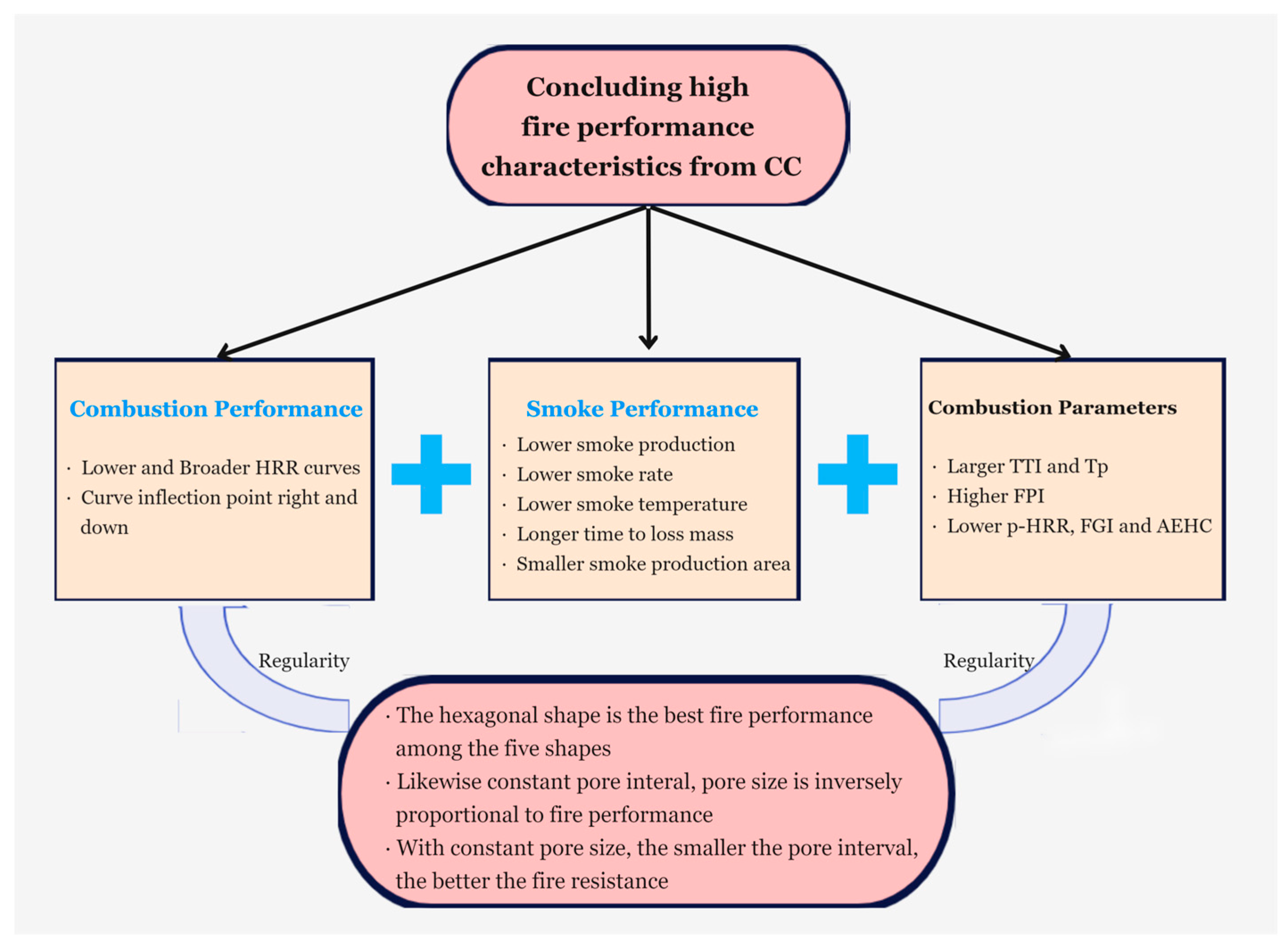
As shown in Figure 3a, the shape of the HRR curve varies substantially with the pore shape—the different pore shapes have different combustion performances, as expected. In particular, the hexagonal shape exerts the optimal fireproof performance with the lowest p-HRR and widest curve, followed by the triangle, parallelogram, honeycomb, and, finally, square pore shapes. In contrast to square holes, the hexagonal pore shape has a 35% lower p-HRR, which reduces the intensity of combustion.
Similarly, the curves in Figure 3b,c indicate a steady increase in the HRR curve with increasing pore size or pore interval, a gradual “upward shift” in p-HRR, and a constant “left shift” in Tp and width of the curve. S2 mm has a p-HRR of just 6.68 kW·m−2·g−1, while the p-HRR for S10mm is 2.51 times greater at 16.79 kW·m−2·g−1. This indicates that combustion is extremely intense and material degradation is quick at a hole interval of 1 mm and a 10 mm diameter hole. The p-HRR value suddenly rises to 13.62 kW·m−2·g−1, which is 1.97 times greater than the 2 mm interval, when the hole interval reaches 10 mm. A conclusion that can be drawn from Figure 3b,c is that the smaller the pore size and interval, the lower the heat transfer. The same conclusion is also reached in GS’s experiments [17].
Additionally, the combustion duration becomes longer for the samples with a hole interval of 2 mm and hole size of 2 mm, exhibiting a “plateau” near the peak compared with the other samples, corresponding to the slow combustion. At this point in the lower steady state, the combustion rate was very low [18], corresponding to the diminished heat transfer. Interestingly, the prolonged combustion duration is accompanied by the diminished p-HRR, due to the faster heat transfer of the samples with the bigger pores. Because the PLA is flammable and the bigger pores provide the precondition for the heat convection within the matrix, which benefits the heat and mass transfer. Meanwhile, the smaller pores hardly form convection and exist only in conduction, due to the inherent thermal boundary layer, which predominates the heat transfer for the samples with smaller pores.
3.2. Smoke Production, Rate, and Temperature
Generally, the flue gas variation pattern is attributable to the fact that PLA does not generate harmful gases such as nitrides and sulfides and instead emits CO2 and H2O during combustion [19]. Figure 4, Figure 5, Figure 6 and Figure 7 show the differences in smoke output, smoke production rate, and flue gas temperature, respectively. Furthermore, Table 2 illustrates the extent of the smoke production area as well as the times when the mass loss exceeds 5%, 30%, 70%, and 95%.
Figure 4a shows that the amount of smoke production varies significantly with pore shape, with the square hole samples producing the most smoke and the hexagonal hole samples exerting the least. In each case, after the combustion reaches its maximum rate, the amount of new flue gas produced gradually decreases, indicating slower combustion. However, the opposite is true for different pore sizes and intervals, as shown in Figure 4b,c, in which the total smoke production curve increases as the pore size or interval increases, indicating that the amount of accumulated smoke produced continues to increase even after the combustion rate reaches its maximum.
The size of the smoke production area also changes significantly for the various pore shape groups, with the Fhexagonal smoke production value being 0.58 times that of the Fsquare value, as shown in Table 2. The area of smoke production for 2 mm holes and 2 mm intervals were only 0.57 and 0.65 times that of the worst samples in the same group, respectively. It is, therefore, evident that hexagonal shapes, S2 mm, produce the lowest amount of smoke, which is more evidence of their superior fireproof performance, corresponding to the weaker heat transfer.
Equally important, the smoke production rate (SPR) follows the same pattern as the temperature change. The plots of smoke generation rates for samples with various pore shapes are shown in Figure 5. As shown in Figure 5a, the samples with square holes present the highest SPR peak and reach it most quickly, while the samples with hexagonal holes have the lowest SPR peak and take the longest time to peak. As shown in Figure 5b,c, the SPR curves move upwards and to the left as pore size and interval rise.
In addition, the flue gas temperature variation graphs in Figure 6 show that it follows the same pattern as the total smoke output and flue gas generation rate curves, with only minor deviations. This is because the data are processed using unit mass calculations to exclude the dependence on mass, which reduces the magnitude of the difference in flue gas temperatures between the various configurations.
Generally, the higher HRR is accompanied by increased SPR or smoke production, because the PLA is flammable with released smoke, and the released heat is proportional to the mass during firing. The faster heat transfer results in an accelerated firing, corresponding to faster combustion. Therefore, Figure 3, Figure 4, Figure 5 and Figure 6 are presented by the unit mass; the faster combustion generates the higher HRR accompanied by the improved SPR with higher smoke temperature.
Several more key factors are shown in Table 2 to provide a more complete picture of the dynamics of different pore configurations in combustion. Full details of the relationship between mass-loss rate and temporal variation are shown in addition to the area of smoke formation. According to Table 2, the hexagonal-hole samples also took longer to reach 5%, 30%, 70%, and 95% mass loss than the other samples. This once again indicates that hexagonal holes hold the optimal fireproof performance. Table 2 also shows that the mass loss rates alter substantially for different hole sizes and intervals, due to the varied heat transfer.
3.3. Combustion Parameters
Table 3 shows the variations in combustion behavior across the samples by presenting the ignition parameters (e.g., TTI, Tp, and p-HRR) as well as the calculated combustion parameters, including the flame growth index (FGI) and flame performance index (FPI).
The combustion behavior parameters of the samples with different pore shapes are shown in Table 3. The combustion performance parameters from the CC measurements demonstrate that the ignition duration increases with hole form, from 32 s (Fsquare) to 43 s (Fhexagonal). The Tp value ranges from 171 s to 273 s—an increase of 102 s and a significant improvement of 60%. Furthermore, the FGI for the hexagonal holes is 0.02 kW∙m−2∙s−1, which is 58% lower than the values for the square pore structure design. Similarly, the FPI of Fhexagonal (7.98 s∙m2∙kW−1) is 2.06 times higher than that of Fsquare (3.88 s∙m2∙kW−1).
Correspondingly, the ignition time for the 2 mm holes is more than double that for the 10 mm holes, Tp is 2.26 times larger, and p-HRR drops to 40%. The dependence of heat transfer on hole interval is similar to the dependence on hole size. Although the differences are not as significant as in the pore size group, the p-HRR value for the 2 mm interval samples is half as good as the value for the 10 mm interval samples, and other combustion performance parameters are better, including FGI and FPI.
To better understand this section, Figure 7 summarizes the characteristics of combustion performance in the CC results. The CC is widely used to evaluate the flame-retarding performance of combustible materials as building materials, which provides the FGI, FPI, and p-HRR for quantitatively evaluating the fireproof performance. The higher flame retardancy corresponds to the lower FGI and p-HRR, while the higher FPI represents the weaker heat transfer essentially. Therefore, the sample S2 mm exhibits the highest flame retardancy corresponding to the weakest heat transfer.
3.4. Discussion
3.4.1. Impact of Pore Shrinkage
As expected, the heat transfer varies between pore-shape structural designs due to the variation in the effective contact area perpendicular to the flow direction. In addition, the holes in the structure are filled with air, which dilutes the combustible material and interrupts some of the heat flow during combustion [20]. Smaller unit cell sizes may constrain the air within the cells, preventing natural convection heat transfer between the cells [21]. The smaller the cell size, the more uniform the temperature distribution [22], rather than the various pressure drops, because the higher heat transfer coefficient leads to a higher pressure drop [23]. Therefore, the convection is constricted while the conduction is only permitted for the samples with smaller cell sizes. Our finding verifies that the smaller pores exert slower combustion under the same firing condition, due to the weaker heat transfer. The inherent thermal boundary region constricts the formation of heat convection essentially. Meanwhile, the molten material could fill the pore during firing and the smaller pores could be sealed; thus, the connection is completely constricted. But it cannot seal the pore with bigger ones; the samples with a diameter of 10 mm generates the strong convection with nonuniform temperature distribution, presenting the accelerated firing, evidenced by enhanced HRR and smoke production. Consequently, the pore shrinkage is thus better achieved when the area of the orifice in contact with the heat flow is small. The strongest pore shrinkage effect prevents the transfer of heat and mass, thus diminishing the heat transfer.
In addition, convection holds faster heat transfer than pure conduction, and the diminished pore benefits restrict the formation of convection during the PLA’s burning. Because the small pore diameter hardly forms the hot-air convection involved in the porous PLA, the air serves as the heat-insulating layer rather than the heating medium during single conduction. Thus, the smaller pores generate the weak heat transfer corresponding to the enhanced flame-retarding performance. When the pore diameter increases, the convection gradually forms and enhances, which accelerates the heat transfer significantly.
3.4.2. Effect of Vortex Heat Dissipation
During combustion, PLA undergoes a phase transition and melts, producing a highly viscous fluid and vortex. Natural convection begins to occur as melting begins [24]. Tang et al. [25] suggest that vorticity can be generated by the shear deformation of the fluid in the boundary layer by the rotation of the fluid in the vortex. The discrepancies in the flow fields of the hole arise mostly from the cavity structure and the radial pressure gradient [26]. Furthermore, there might be also interstitial heat transfer [27] for the samples with bigger pores; the air within the cavity is driven to create rotating circles of different sizes from the cavity interior under the action of the flow field, resulting in vortices and small swirls at the corners of holes. The peak temperature inside a cavity rises as the radius of the rotating circle grows [28]. This causes a significant temperature gradient between the inside and outside of the cavity, which increases the convection velocity and the heat transfer area and continues to raise the heat dissipation efficiency from the inside of the cavity to the environment. It has been demonstrated that the attachment force begins to dominate as thermal energy dissipation increases strongly, which also means that the convection rate further accelerates [29]. Consequently, the bigger pore provides the preconditions for the vortex formation, which is prone to enhanced temperature gradient, thus strengthening the vortex heat dissipation, corresponding to the faster heat transfer.
4. Conclusions
This study aims to understand how different porous structures within PLA affect heat transfer and combustion. Experimental tests reveal that altering the material’s structural design significantly impacts its heat transfer, with specific structures exhibiting optimal fire resistance and reduced heat transfer. Three-dimensional printing has been adopted to design the various porous structures of PLA, flame retardancy is employed to evaluate its heat-transfer property indirectly, and the key conclusions are drawn as follows.
The heat-transfer behavior of PLA varies from different cavity structures constructed by 3D printing, evidenced by the different FGI and HRR from CC testing, inferring that the heat transfer efficiency can be adjusted by changing the physical structure of the material, rather than adding flame retardants. Of the structures examined, those with hexagonal holes, 2 mm holes, and 2 mm hole intervals exhibit optimal fireproof performance and the p-HRR are only 65%, 40%, and 51% of the worst flame retardancy, respectively, corresponding to diminished heat transfer.
The research paves the way for more efficient porous thermal management materials and raises intriguing questions about the relationships between pore structure and combustion performance. However, the next challenge is to investigate the coupling effect among pore shape, size, and interval, exploring the influence on the heat transfer of porous PLA, as well as the porous PLA with nonequal sections or other complex structures.
Author Contributions
Conceptualization, C.Y. and Y.W.; methodology, Y.W.; software, Y.W.; validation, C.Y. and Y.W.; formal analysis, Y.W.; investigation, Y.W.; resources, C.Y.; data curation, Y.W.; writing—original draft preparation, C.Y.; writing—review and editing, Y.W.; visualization, Y.W.; supervision, Y.W.; project administration, C.Y. All authors have read and agreed to the published version of the manuscript.
Funding
This research received no external funding.
Institutional Review Board Statement
Not applicable.
Informed Consent Statement
Not applicable.
Data Availability Statement
Suggested Data Availability Statements are available in section.
Conflicts of Interest
The authors declare no conflict of interest.
References
- Shi, S.; Dai, M.; Tao, X.; Wu, F.; Sun, J.; Chen, Y. 3D printed polylactic acid/graphene nanocomposites with tailored multifunctionality towards superior thermal management and high-efficient electromagnetic interference shielding. Chem. Eng. J. 2022, 450, 138248. [Google Scholar] [CrossRef]
- Baobaid, N.; Ali, M.I.; Khan, K.A.; Al-Rub, R.K.A. Fluid flow and heat transfer of porous TPMS architected heat sinks in free convection environment. Case Stud. Therm. Eng. 2022, 33, 101944. [Google Scholar] [CrossRef]
- Hu, X.S.; Gong, X.L. Experimental study on the thermal response of PCM-based heat sink using structured porous material fabricated by 3D printing. Case Stud. Therm. Eng. 2021, 24, 100844. [Google Scholar] [CrossRef]
- Geoffroy, L.; Samyn, F.; Jimenez, M.; Bourbigot, S. Innovative 3D printed design to conceive highly fire-retardant multi-material. Polym. Degrad. Stab. 2019, 169, 108992. [Google Scholar] [CrossRef]
- Li, X.; Wang, C.; Tian, C.; Fu, S.; Rong, Y.; Wang, L. Digital design and performance evaluation of porous metal-bonded grinding wheels based on minimal surface and 3D printing. Mater. Des. 2021, 203, 109556. [Google Scholar] [CrossRef]
- Pan, Z.Z.; Lv, W.; Yang, Q.H.; Nishihara, H. Aligned macroporous monoliths by ice-templating. Bull. Chem. Soc. Jpn. 2022, 95, 611–620. [Google Scholar] [CrossRef]
- Vazic, B.; Abali, B.E.; Yang, H.; Newell, P. Mechanical analysis of heterogeneous materials with higher-order parameters. Eng. Comput. 2021, 38, 5051–5067. [Google Scholar] [CrossRef]
- Malik, R.; Kim, Y.W.; Song, I.H. High interfacial thermal resistance induced low thermal conductivity in porous SiC-SiO2 composites with hierarchical porosity. J. Eur. Ceram. Soc. 2020, 40, 594–602. [Google Scholar] [CrossRef]
- Fleet, C.T.; Straatman, A.G. A model for the conduction shape factor in spherical void phase porous material. Int. J. Heat Mass Transf. 2021, 164, 120583. [Google Scholar] [CrossRef]
- Ji, G.; Fang, Y.; Zhou, J. Porous acoustic metamaterials in an inverted wedge shape. Extrem. Mech. Lett. 2020, 36, 100648. [Google Scholar] [CrossRef]
- Chen, J.; Jiang, L.; Wang, W.; Wang, P.; Li, X.; Ren, H.; Wang, Y. Facile construction of highly porous carbon materials derived from porous aromatic frameworks for greenhouse gas adsorption and separation. Microporous Mesoporous Mater. 2021, 326, 111385. [Google Scholar] [CrossRef]
- Shi, J.; Zhang, L.; Xiao, P.; Huang, Y.; Chen, P.; Wang, X.; Gu, J.; Zhang, J.; Chen, T. Biodegradable PLA nonwoven fabric with controllable wettability for efficient water purification and photocatalysis degradation. ACS Sustain. Chem. Eng. 2018, 6, 2445–2452. [Google Scholar] [CrossRef]
- Rydz, J.; Sikorska, W.; Kyulavska, M.; Christova, D. Polyester-based (bio)degradable polymers as environmentally friendly materials for sustainable development. Int. J. Mol. Sci. 2014, 16, 564–596. [Google Scholar] [CrossRef] [PubMed]
- Yin, Z.Y.; Wang, P.; Zhang, F. Effect of particle shape on the progressive failure of shield tunnel face in granular soils by coupled FDM-DEM method. Tunn. Undergr. Space Technol. 2020, 100, 103394. [Google Scholar] [CrossRef]
- Wang, Y.; Deng, J.; Zhao, J.; Shi, H. Benign design intumescent flame-retarding aliphatic waterborne polyester coatings modified by precipitated silica aerogel and aluminum powder. J. Mater. Res. Technol. 2021, 15, 6125–6135. [Google Scholar] [CrossRef]
- McCoy, C.G.; Stoliarov, S.I. Experimental characterization and modeling of boundary conditions and flame spread dynamics observed in the UL-94V test. Combust. Flame 2021, 225, 214–227. [Google Scholar] [CrossRef]
- Ghorashi, S.A.; Hashemi, S.M.; Hashemi, S.A.; Mollamahdi, M. Numerical study on the combustion characteristics in a porous-free flame burner for lean mixtures. Proc. Inst. Mech. Eng. Part C J. Mech. Eng. Sci. 2020, 234, 935–945. [Google Scholar] [CrossRef]
- Kim, J.H.; Jang, Y.S.; Kim, D.H. Multiple steady states in the oxidative steam reforming of methanol. Chem. Eng. J. 2018, 338, 725–763. [Google Scholar] [CrossRef]
- Lv, S.; Zhang, Y.; Tan, H. Thermal and thermo-oxidative degradation kinetics and characteristics of poly (lactic acid) and its composites. Waste Manag. 2019, 87, 335–344. [Google Scholar] [CrossRef]
- Duva, B.C.; Chance, L.E.; Toulson, E. Dilution effect of different combustion residuals on laminar burning velocities and burned gas Markstein lengths of premixed methane/air mixtures at elevated temperature. Fuel 2020, 267, 117153. [Google Scholar] [CrossRef]
- Catchpole-Smith, S.; Sélo RR, J.; Davis, A.W.; Ashcroft, I.A.; Tuck, C.J.; Clare, A. Thermal conductivity of TPMS lattice structures manufactured via laser powder bed fusion. Addit. Manuf. 2019, 30, 100846. [Google Scholar] [CrossRef]
- Gao, S.; Qu, S.; Ding, J.; Liu, H.; Song, X. Influence of cell size and its gradient on thermo-hydraulic characteristics of triply periodic minimal surface heat exchangers. Appl. Therm. Eng. 2023, 232, 121098. [Google Scholar] [CrossRef]
- Samson, S.; Tran, P.; Marzocca, P. Design and modelling of porous gyroid heatsinks: Influences of cell size, porosity and material variation. Appl. Therm. Eng. 2023, 235, 121296. [Google Scholar] [CrossRef]
- Azad, M.; Groulx, D.; Donaldson, A. Natural convection onset during melting of phase change materials: Part II—Effects of Fourier, Grashof, and Rayleigh numbers. Int. J. Therm. Sci. 2021, 170, 107062. [Google Scholar] [CrossRef]
- Tang, W.; Zhou, H.; Zeng, Y.; Yan, M.; Jiang, C.; Yang, P.; Li, Q.; Li, Z.; Fu, J.; Huang, Y.; et al. Analysis on the convective heat transfer process and performance evaluation of Triply Periodic Minimal Surface (TPMS) based on Diamond, Gyroid and Iwp. Int. J. Heat Mass Transf. 2023, 201, 123642. [Google Scholar] [CrossRef]
- Farthing, P.R.; Long, C.A.; Owen, J.M.; Pincombe, J.R. Rotating cavity with axial throughflow of cooling air: Flow structure. J. Turbomach. 1992, 114, 237–246. [Google Scholar] [CrossRef]
- Qureshi, Z.A.; Elnajjar, E.; Al-Ketan, O.; Al-Rub, R.A.; Al-Omari, S.B. Heat transfer performance of a finned metal foam-phase change material (FMF-PCM) system incorporating triply periodic minimal surfaces (TPMS). Int. J. Heat Mass Transf. 2021, 170, 121001. [Google Scholar] [CrossRef]
- Shih, Y.C.; Khodadadi, J.M.; Weng, K.H.; Ahmed, A. Periodic fluid flow and heat transfer in a square cavity due to an insulated or isothermal rotating cylinder. J. Heat Transf. Trans. Asme 2009, 131, 1314–1316. [Google Scholar] [CrossRef]
- Sun, X.; Meng, H. Large eddy simulations and analyses of hydrocarbon fuel heat transfer in vertical upward flows at supercritical pressures. Int. J. Heat Mass Transf. 2021, 170, 120988. [Google Scholar] [CrossRef]
Figure 1.
Process diagram of the entire process.
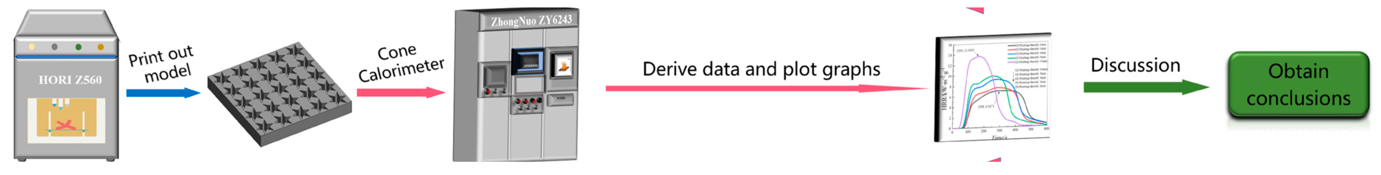
Figure 2.
The parameters and shapes of tested models.
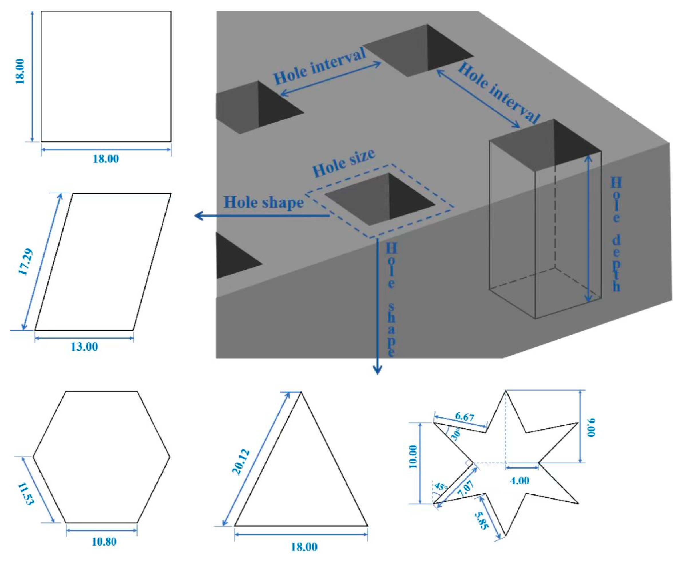
Figure 3.
HRR curves for different pore structures. (a) Pore shape; (b) hole size; (c) hole interval.
Figure 3.
HRR curves for different pore structures. (a) Pore shape; (b) hole size; (c) hole interval.
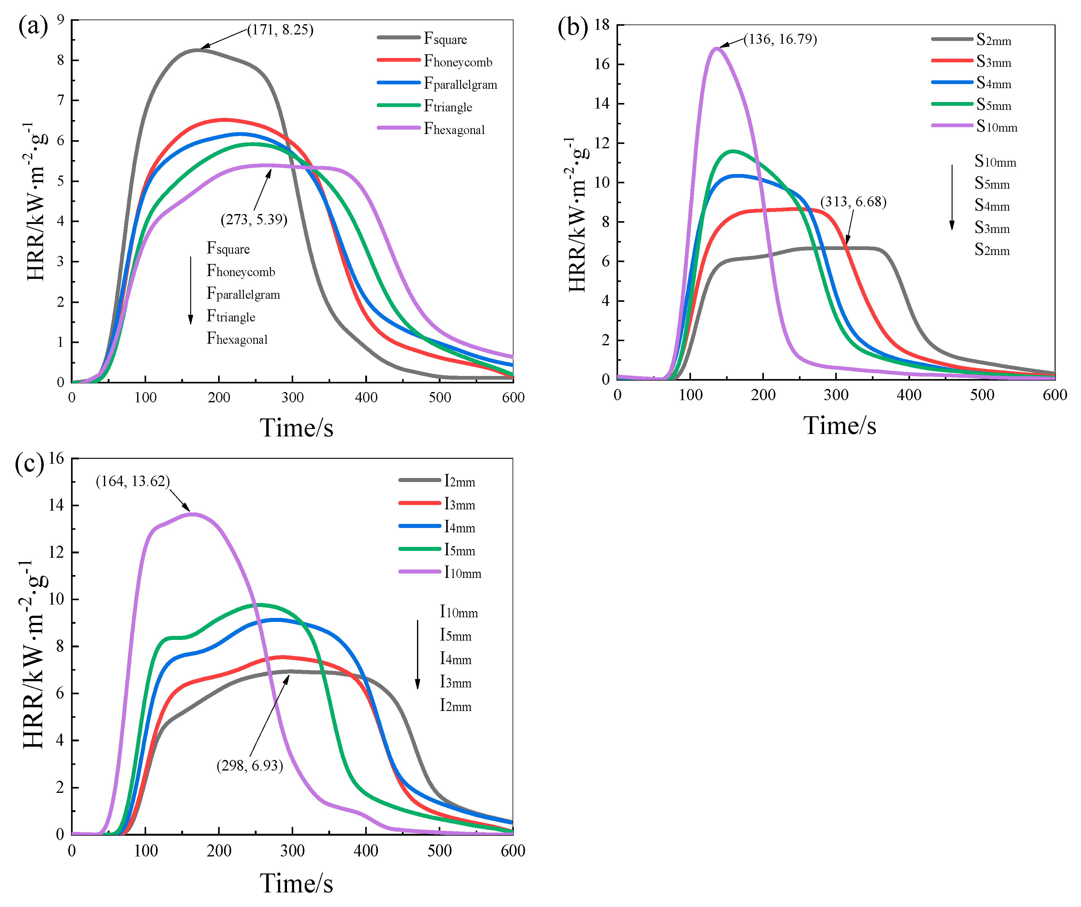
Figure 4.
Smoke production curves for different pore structures. (a) Pore shape; (b) hole size; (c) hole interval.
Figure 4.
Smoke production curves for different pore structures. (a) Pore shape; (b) hole size; (c) hole interval.
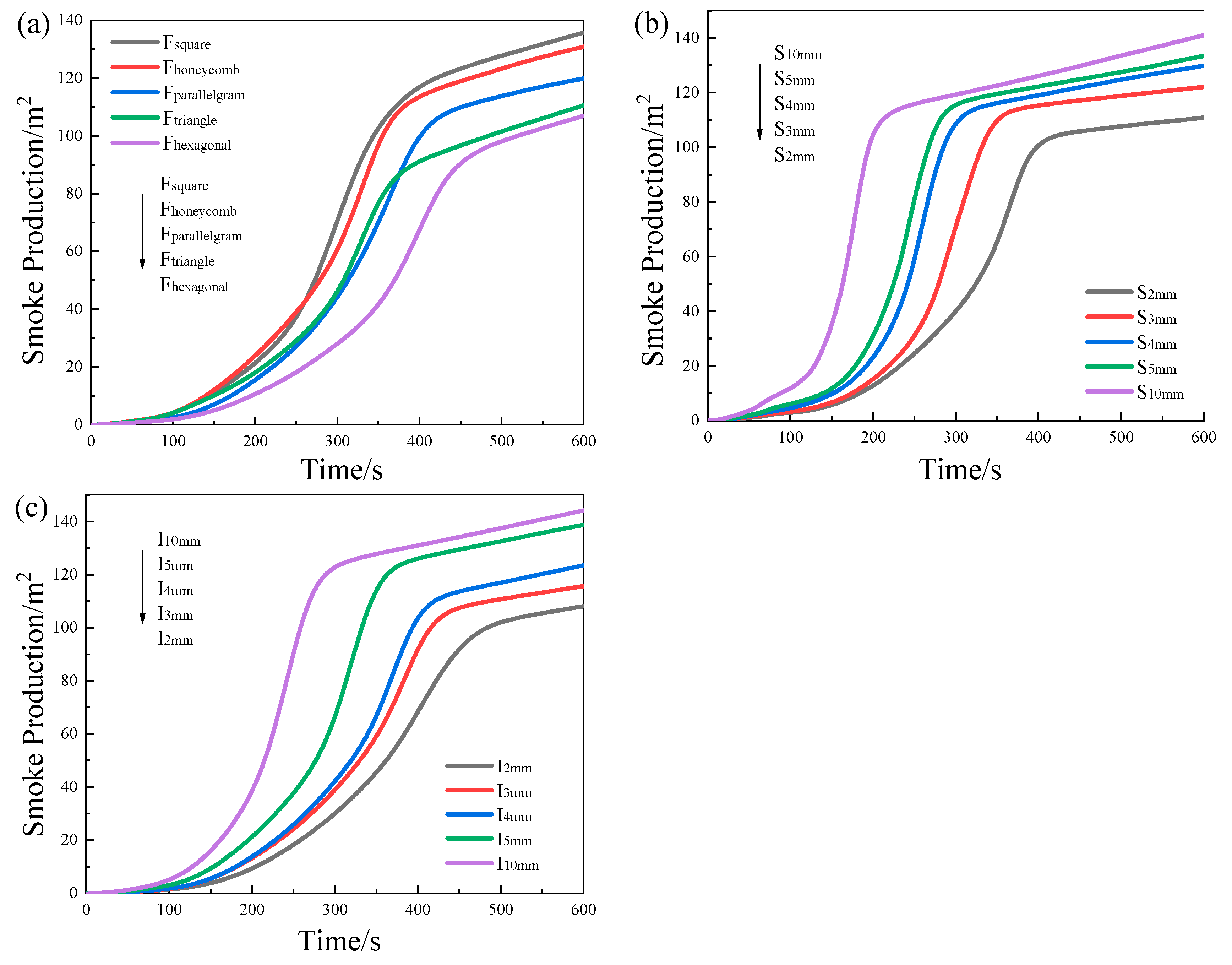
Figure 5.
Smoke production rate of different pore structures. (a) Pore shape; (b) hole size; (c) hole interval.
Figure 5.
Smoke production rate of different pore structures. (a) Pore shape; (b) hole size; (c) hole interval.

Figure 6.
Smoke temperature curves of different pore structures. (a) Pore shape; (b) hole size; (c) hole interval.
Figure 6.
Smoke temperature curves of different pore structures. (a) Pore shape; (b) hole size; (c) hole interval.
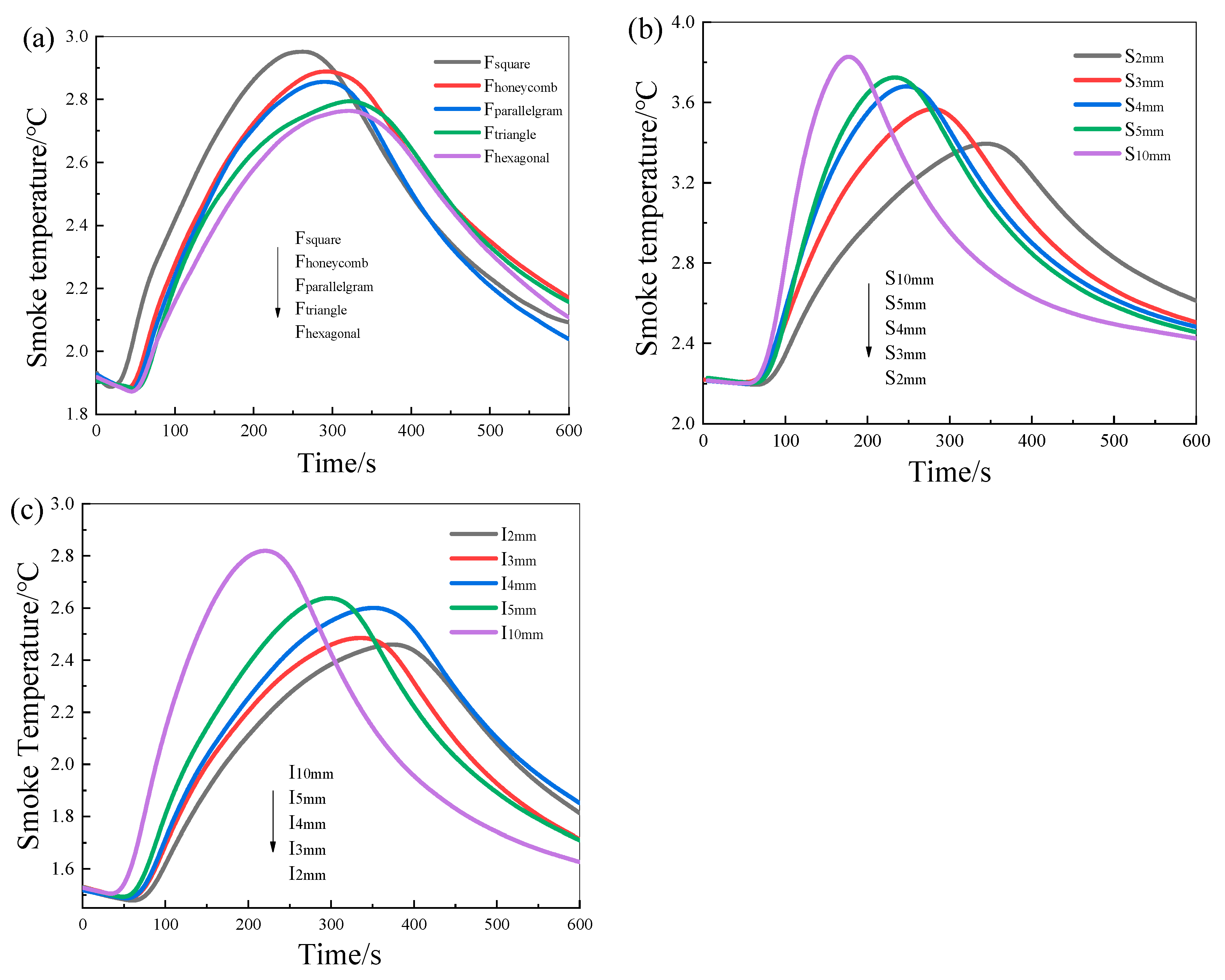
Figure 7.
The characteristics of combustion performance in the CC results.

Table 1.
Sample parameters for experiments I, II, and III.
| Samples | Pore Shape | Hole Size/mm | Hole Interval/mm | Porosity/% | Printing Time/min | Sample Weight/g | |
|---|---|---|---|---|---|---|---|
| EXP. I | Fsquare | square | 18 | 2 | 65 | 202 | 33.75 |
| Fhoneycomb | honeycomb | 18 | 2 | 52 | 233 | 35.67 | |
| Fparallelogram | parallelogram | 18 | 2 | 47 | 242 | 36.19 | |
| Ftriangle | triangle | 18 | 2 | 33 | 249 | 38.25 | |
| Fhexagonal | hexagonal | 18 | 2 | 25 | 301 | 43.71 | |
| EXP. II | S2 mm | square | 2 | 1 | 33 | 414 | 36.11 |
| S3mm | square | 3 | 1 | 41 | 320 | 30.25 | |
| S4mm | square | 4 | 1 | 46 | 232 | 25.70 | |
| S5mm | square | 5 | 1 | 51 | 197 | 22.61 | |
| S10mm | square | 10 | 1 | 65 | 102 | 13.34 | |
| EXP. III | I2mm | square | 2 | 2 | 20 | 396 | 46.84 |
| I3mm | square | 2 | 3 | 13 | 372 | 42.29 | |
| I4mm | square | 2 | 4 | 10 | 348 | 39.68 | |
| I5mm | square | 2 | 5 | 6 | 322 | 35.13 | |
| I10mm | square | 2 | 10 | 3 | 173 | 24.40 | |
Table 2.
Time variation in mass loss of different pore structures.
| Samples | Fsquare | Fhoneycomb | Fparallelogram | Ftriangle | Fhexagonal | S2 mm | S3 mm | S4 mm | S5 mm | S10 mm | I2 mm | I3 mm | I4 mm | I5 mm | I10 mm |
|---|---|---|---|---|---|---|---|---|---|---|---|---|---|---|---|
| T5% | 52 | 57 | 61 | 67 | 73 | 86 | 75 | 65 | 52 | 34 | 80 | 78 | 73 | 66 | 48 |
| T30% | 123 | 142 | 137 | 163 | 173 | 168 | 139 | 121 | 109 | 93 | 161 | 149 | 134 | 119 | 104 |
| T70% | 241 | 274 | 267 | 311 | 333 | 302 | 272 | 244 | 208 | 151 | 294 | 268 | 244 | 227 | 188 |
| T95% | 537 | 558 | 562 | 587 | 600 | 600 | 600 | 564 | 510 | 488 | 600 | 600 | 600 | 578 | 546 |
| Smoke production area/m2 | 72.18 | 63.57 | 59.74 | 53.85 | 42.24 | 32.41 | 39.43 | 45.38 | 47.83 | 56.40 | 41.18 | 53.57 | 59.74 | 63.85 | 72.24 |
T5%: 5% mass loss time.
Table 3.
The combustion parameter values of different pore structures.
| Samples | TTI/s | Tp/s | THR/MJ∙m−2∙g−1 | p-HRR/kW∙m−2 | FPI/s∙m2∙kW−1 | FGI/kW∙m−2∙s−1 |
|---|---|---|---|---|---|---|
| Fsquare | 32 | 171 | 2.02 | 8.25 | 3.88 | 0.05 |
| Fhoneycomb | 33 | 208 | 1.88 | 6.52 | 5.06 | 0.03 |
| Fparallelogram | 36 | 230 | 1.85 | 6.17 | 5.84 | 0.03 |
| Ftriangle | 39 | 246 | 1.79 | 5.96 | 6.64 | 0.02 |
| Fhexagonal | 43 | 273 | 1.64 | 5.39 | 7.98 | 0.02 |
| S2 mm | 63 | 307 | 1.82 | 6.68 | 9.43 | 0.02 |
| S3 mm | 58 | 247 | 2.07 | 8.66 | 6.70 | 0.04 |
| S4 mm | 51 | 166 | 2.08 | 10.35 | 4.93 | 0.06 |
| S5 mm | 44 | 159 | 2.13 | 11.58 | 3.80 | 0.07 |
| S10 mm | 31 | 136 | 2.24 | 16.79 | 1.85 | 0.12 |
| I2 mm | 61 | 298 | 2.24 | 6.93 | 8.81 | 0.02 |
| I3 mm | 57 | 260 | 2.35 | 7.53 | 7.57 | 0.03 |
| I4 mm | 50 | 278 | 2.43 | 9.13 | 5.48 | 0.03 |
| I5 mm | 45 | 255 | 2.59 | 9.77 | 4.61 | 0.04 |
| I10 mm | 39 | 164 | 2.88 | 13.62 | 3.36 | 0.07 |
Disclaimer/Publisher’s Note: The statements, opinions and data contained in all publications are solely those of the individual author(s) and contributor(s) and not of MDPI and/or the editor(s). MDPI and/or the editor(s) disclaim responsibility for any injury to people or property resulting from any ideas, methods, instructions or products referred to in the content. |
© 2023 by the authors. Licensee MDPI, Basel, Switzerland. This article is an open access article distributed under the terms and conditions of the Creative Commons Attribution (CC BY) license (https://creativecommons.org/licenses/by/4.0/).
Share and Cite
MDPI and ACS Style
Yuan, C.; Wang, Y. Combustion Performance of Various Polylactic Acid Plastics with Different Porous Structures Constructed by 3D Printing. Fire 2023, 6, 425. https://doi.org/10.3390/fire6110425
AMA Style
Yuan C, Wang Y. Combustion Performance of Various Polylactic Acid Plastics with Different Porous Structures Constructed by 3D Printing. Fire. 2023; 6(11):425. https://doi.org/10.3390/fire6110425
Chicago/Turabian StyleYuan, Chao, and Yachao Wang. 2023. "Combustion Performance of Various Polylactic Acid Plastics with Different Porous Structures Constructed by 3D Printing" Fire 6, no. 11: 425. https://doi.org/10.3390/fire6110425