Motion-Based Design of Passive Damping Devices to Mitigate Wind-Induced Vibrations in Stay Cables
by
 , and
, and
Javier Naranjo-Pérez
1 ,
,
Javier Jiménez-Manfredi
1,
Javier F. Jiménez-Alonso
2,* and
Andrés Sáez
1 1
Department of Continuum Mechanics & Structural Analysis, Universidad de Sevilla, 41004 Sevilla, Spain
2
Department of Building Structures & Geotechnical Engineering, Universidad de Sevilla, 41004 Sevilla, Spain
*
Author to whom correspondence should be addressed.
Vibration 2018, 1(2), 269-289; https://doi.org/10.3390/vibration1020019
Submission received: 2 September 2018
/
Revised: 22 October 2018
/
Accepted: 7 November 2018
/
Published: 12 November 2018
(This article belongs to the Special Issue Vibration Serviceability of Civil Engineering Structures)
Abstract
:Wind action can induce large amplitude vibrations in the stay cables of bridges. To reduce the vibration level of these structural elements, different types of passive damping devices are usually installed. In this paper, a motion-based design method is proposed and implemented in order to achieve the optimum design of different passive damping devices for stay cables under wind action. According to this method, the design problem is transformed into an optimization problem. Thus, its main aim is to minimize the different terms of a multi-objective function, considering as design variables the characteristic parameters of each considered passive damping device. The multi-objective function is defined in terms of the scaled characteristic parameters, one single-function for each parameter, and an additional function that checks the compliance of the considered design criterion. Genetic algorithms are considered as a global optimization method. Three passive damping devices have been studied herein: viscous, elastomeric and friction dampers. As a benchmark structure, the Alamillo bridge (Seville, Spain), is considered in order to validate the performance of the proposed method. Finally, the parameters of the damping devices designed according to this proposal are successfully compared with the results provided by a conventional design method.
1. Introduction
Cable-stayed bridges have experienced great growth since the second half of the 20th century due to both their low cost and their good performance in low-strength soils with respect to other typologies. Stay cables, characterized by their high flexibility and low damping, are the main structural elements that distinguish this type of bridge. However, both properties are main causes of the propensity of the cables to vibrate due to wind-induced excitations. The vibratory phenomenon can cause both comfort and fatigue problems.
Perhaps the first case in which problems associated with cable oscillations were reported was the Brotonne Bridge (France), in 1976 [1]. The longest cables of this bridge, which were parallel and separated by around 2 m, came into contact due to the occurrence of high-amplitude wind-induced vibrations [2]. Currently, researchers are focused on both controlling the effects of dynamic loads (such as earthquake and extreme wind [3,4,5]) on stay cables and the analysis of their static non-linear behavior [6].
To control the dynamic response of stay cables under wind action, vibration control systems have been widely used. These systems can be classified into three groups: active, semi-active and passive control systems. Active control systems modify the dynamic response of the stay cable via the coordinated action of a data acquisition system, a controller and an actuator. The technological development of these active control systems is recent, so there are still limited cases of their real practical application in cable-stayed bridges. Semi-active control systems follow a similar strategy to active control systems, but in this case, the actuator does not directly apply a force to the system, but instead controls the parameters of a passive damping device, called a controllable passive damping device. There are several examples in the literature of the use of semi-active systems to control the response of stay cables under dynamic actions. Thus, Zhou and Sun checked the effectiveness of magnetorheological dampers to increase the damping of stay cables [7]; subsequently, Yeganeh Fallah et al. proposed the use of magnetorheological dampers to mitigate seismic-induced vibrations in these structural elements under uncertainty conditions [8], and more recently, Zhou et al. have shown the high performance of semi-active control devices based on the modification of a conventional passive damper via the implementation of concentrated masses [9]. Finally, passive control systems, in which a device is installed in the structure in order to increase its damping, have been widely used to tackle the problem of wind-induced vibrations in stay cables of bridges. The passive control systems may be classified in three groups in terms of their operating mode: (i) mechanical mode, which modifies the damping of the cable; (ii) structural mode, which modifies the natural frequency (for example crossing cables, the so-called crossties); and (iii) aerodynamic mode, which modifies the cross-sectional configuration of the cable [10]. Although structural and aerodynamic control modes have been applied frequently in the past, the current trend is towards the use of mechanical passive control systems [10]. Due to their high efficiency and reliability, they are being installed on a large number of cable-stayed bridges to mitigate wind-induced vibrations [11]. These passive control devices increase the damping capacity of the cables, reducing, in this manner, the amplitude of their dynamic response. A key point to be considered during the design phase of the dampers is to ensure an adequate value of the damping ratio for all the considered vibration modes in order to ensure a high performance of the control system [12].
Several authors have developed models and criteria for the optimum design of passive control systems for stay cables [13,14]. Most of these authors share the same criterion to measure the effectiveness of the passive control system: the ratio between the damping coefficient of the cable and its critical damping capacity.
The optimum design of dampers installed close to the anchorage was first studied by Kovacs [15], who estimated the optimum damping of a viscous damper. Subsequently, Pacheco et al. [16] proposed a universal curve, which represents the modal damping of a taut cable for the lower natural frequencies in terms of the damping coefficient of the damper. This curve has been widely used for the preliminary design of dampers for stay cables. The maximum of this curve shows the optimum damping ratio of the cable when a damper is attached. Yoneda and Maeda [17] proposed, based on the analytical model of a damped cable, the optimum damper size and its corresponding modal damping ratio. The results provided by Kovacs, Pacheco et al. and Yoneda and Maeda are in good agreement. Thus, given a particular geometry and mechanical properties of a cable, the maximum damping ratio estimated, when a viscous damper is installed, according to these three different proposals is similar. A significant breakthrough was developed by Krenk [18], who obtained an analytical expression of the Pacheco’s universal curve based on the solution of a numerical complex eigenvalues problem.
To simulate numerically the dynamic response of the damper-cable interaction model under wind action, the following factors must be taken into account [10]: (i) the geometrical nonlinear behavior of the cable, (ii) its low damping, (iii) its bending stiffness, (iv) its post-tensioning stress, and (v) the constitutive model of the damper. The influence of these factors on the dynamic behavior of this structural system has been studied widely. First, Mehrabi and Tabatai [19] solved the problem of the sagging cable equipped with a viscous damper, using the finite difference method and considering both the effect of the curvature of the cable and its bending stiffness. The results of this study showed that the maximum damping ratio considering the bending stiffness is 8% higher than the value provided by the Pacheco’s universal curve (which neglects this effect). Thus, these authors concluded that the effect of bending stiffness is very significant while the curvature of the cable can be disregarded. Subsequently, Hoang and Fujino [20] deduced an analytical equation for the maximum attainable modal damping of the cable. The results revealed that the efficiency of the damper and the maximum damping ratio decreased in terms of the increase of the bending stiffness. Finally, Cheng et al. [21] determined the increase of the damping of the damper-cable interaction system in terms of the decay ratio of the kinetic energy of the cable. All these results have been considered herein in order to model numerically the damper-cable interaction phenomenon.
In this paper, a motion-based design method is proposed and implemented in order to reduce the wind-induced vibrations in stay cables of bridges. The method initially proposed by Connor [22] to control the response of tall buildings under wind and earthquake action is herein adapted to control wind-induced vibrations in stay cables. Previously, the authors have successfully adapted this method to design optimum tuned mass dampers for vibrating footbridges under pedestrian action [23]. A similar approach was proposed by Ontiveros et al. [24] to determine the optimum parameters of friction dampers in buildings.
The motion-based design method transforms the design problem into an optimization problem. The main objective of the optimization problem is to minimize the different terms of a multi-objective function considering as design variables the characteristic parameters of the considered passive damping devices. The multi-objective function is defined in terms of the scaled characteristic parameters of the considered passive damping device, one single-function for each parameter, and an additional function that verifies the compliance of the considered design criterion. As an optimization method, genetic algorithms have been considered. As a design criterion, the compliance of the vibration serviceability limit state of the cable, according to the recommendations of the FHWA guidelines [25], was considered. The maximum displacement threshold has been established for each cable according to these standards. A search domain has been established for each design variable. The design of three different passive damping devices (viscous, elastomeric and friction damper) was undertaken in this study. As result of the optimization process, different Pareto fronts have been obtained. The analysis of these Pareto fronts makes it possible to find an optimal design for each passive damping device. As an optimal solution, the one which minimizes the characteristic parameter of the damper, meets the considered design criterion, have been selected. As wind-induced excitation, both the rain-wind induced vibrations and the turbulent component of the wind action were considered in this study for the sake of conciseness and clarity. Nevertheless, the proposed method may be applied to solve the design problem under other wind-induced vibratory phenomena (vortex shedding, etc.) [26]. In this study, the wind action was defined according to the recommendations of the Eurocode [27]. Numerical simulations of the wind action were generated via the implementation of the wave superposition spectral-based method [28,29] in the mathematical package Matlab [30].
Finally, the proposed method was validated numerically via the optimum design of the three mentioned passive damping devices in order to reduce the wind-induced vibrations of a real structure. One of the longest cables of the Alamillo bridge (Seville, Spain) [31] was considered as benchmark. A damper-cable interaction model has been proposed based on the finite element (FE) method. The software package Ansys [32] was employed for this purpose. Both numerical modal and transient analysis were performed based on this FE model. As the cable did not meet the design criteria established, three different passive damping devices were implemented on the cable and designed independently. The design of the dampers was performed via the motion-based design method. The design process was implemented through a linking between the software packages Ansys [32] and Matlab [30]. As result of the design process, the characteristic parameters of these three passive damping devices were determined. Finally, a comparison was made between the results obtained by this method and the values provided by a conventional design method [16].
The main advantages of the proposed method are: (i) the reduction of the characteristic parameters of the passive damping devices against the values provided by a conventional design method [16]; and (ii) the method allows addressing the design of the different type of passive damping devices in a general way, simplifying the decision making of selecting the best damper for each particular practical case. In this manner, the proposed method allows a reduction in the cost and size of the passive damping devices, therefore making their installation easier.
The paper is organized as follows. First, the damper-cable interaction model is described. Second, the basics of the motion-based design method for the passive control of structural systems are described. Third, the performance of the proposed method for the passive control of a stay cable is validated. A numerical validation example, the control of the wind-induced vibrations of one of the longest cables of the Alamillo bridge, is developed for this purpose. Finally, some concluding remarks are drawn to close the paper.
2. Numerical Modelling of the Damper-Cable Interaction Model
The finite element method has been considered to simulate numerically the structural behavior of the damper-cable interaction model. The software program Ansys [32] was used for this purpose.
According to the results of the above-mentioned research, the bending stiffness of the cable was considered in this study. The 3D beam element (BEAM188) was selected to simulate the behavior of the cable. Thus, the considered element is a nonlinear two-node beam element with six degrees of freedom for each node. Both the stress-stiffness and the large-strain analysis options were taken into account herein.
Three passive damping devices (viscous, elastomeric and friction damper) were considered. These three types collect the dampers commonly used in real practical applications [10]. A linear behavior of the constitutive law of each damper was assumed in this study. The energy dissipated by each passive damping device depends on the damping force, , which characterizes its structural behavior (N). The damping force is opposed to the movement of the cable. The definition of the damping force varies in terms of the type of passive damping device considered. The constitutive laws of each damper and the finite element considered for its numerical simulation are described in the following paragraphs.
For a viscous damper, the damping force, , is defined in terms of the damping coefficient, (sN/m), and the relative velocity between the two extremes of the damper (m/s) (being the time variable (s)). The damping force generated by a viscous damper may be defined as follows [33,34]:
Figure 1a shows the viscous damper-cable interaction model considered herein. The element COMBIN14 has been selected to simulate numerically the behavior of this damper. The characteristic parameter of this damper is the damping coefficient, .
For an elastomeric damper, the damping force, , is defined in terms of two components: (i) a viscous damping component and (ii) an elastic component. Thus, this damper is characterized by a viscoelastic behavior. The viscous damping component is defined in terms of the damping coefficient, , and the relative velocity, . The elastic component is defined in terms of the stiffness coefficient, (N/m), and the relative displacement between the two extremes of the damper, (m). The damping force generated by an elastomeric damper may be expressed as follows [35,36]:
Figure 1b shows the elastomeric damper-cable interaction model considered herein. The element COMBIN14 was selected again to model the dynamic behavior of this damper. The characteristic parameters of this damper are the damping coefficient, , and stiffness coefficient, .
Finally, for a friction damper, the damping force, , is defined in terms of three components: (i) a viscous damping component, (ii) an elastic component, and (iii) a friction component. This damper dissipates energy via the relative movement between two surfaces in contact [37]. Thus, a minimum value of the transversal force must be exceeded in order to start releasing energy. The viscous damping component is defined in terms of the damping coefficient, , and the relative velocity, . The elastic component is defined in terms of the stiffness coefficient, , and the relative displacement, . Finally, the friction component is defined in terms of the static friction force, (N) ( being the friction coefficient (−) and the normal force (N)), and a symbolic function, (defined as −1, 0 and 1, respectively in case , and ). The damping force generated by a friction damper may be defined as follows [38]:
Figure 1c shows the friction damper-cable interaction model considered herein. The element COMBIN40 has been selected to simulate numerically the behavior of this damper. The characteristic parameters of this damper are the damping coefficient, , the stiffness coefficient, , and the friction force, . In Figure 1c, the friction force, , is denoted as, , according to the notation provided by the software package Ansys [32].
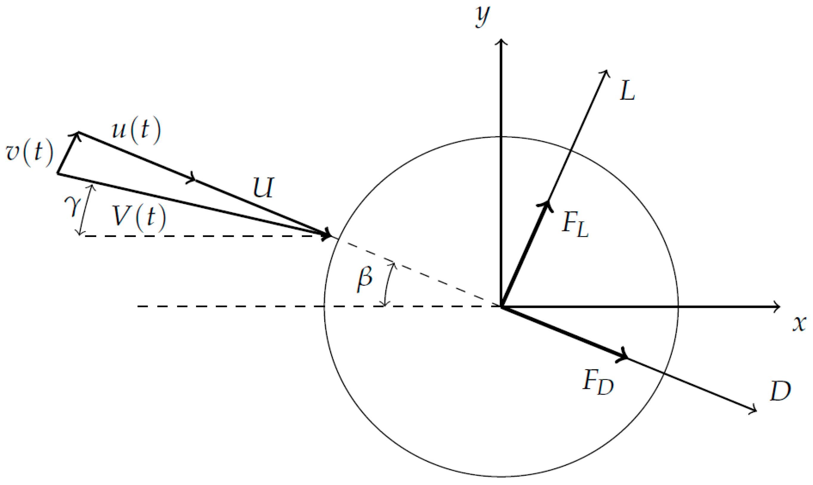
Finally, the definition of the wind action is computed. For this purpose, it is assumed that the cable is a cylinder immersed in a turbulent flow characterized by the mean wind velocity, (m/s), and the fluctuating longitudinal, (m/s), and transverse velocities, (m/s) (Figure 2).
The wind velocities may be simulated numerically via the application of the wave superposition spectral-based method [28,29]. According to this method, the wind velocity can be determined numerically through a superposition of trigonometric functions with random phase angles. The amplitude of these trigonometric functions is obtained from both the power spectral density function of the turbulent wind velocity and a coherence function which takes into account the spatial variability of the wind velocity. The power spectral density function of the wind velocity was defined by several international standards. The proposal of Eurocode was adopted herein [27]. As coherence function, the relationship proposed by Davenport [39] has been taken into account in this study. Thus, a software application [29] was programmed in the mathematical package Matlab [30] in order to simulate the wind action.
Subsequently, the wind force can be determined assuming both the quasi-steady theory model assumption and that the turbulence components are small with respect to the mean wind velocity [26]. The wind force may be decomposed into a mean component and a fluctuating component [40]. Thus, the drag, (N), and lift, (N), forces can be obtained, based on a linearized approximation as [41]:
The mean wind drag force, (N), the mean lift force, (N), the forces induced by the turbulence component in the drag direction, denoted as (N) and (N), and the forces induced by the turbulence component in the lift direction, denoted as (N) and (N), may be defined according to the following expressions [10]:
where is the air density (kg/m3), is the drag coefficient (−), is the lift coefficient (−), is the derivative (−) of in terms of the angle, (rad), at the neighborhood of (rad) (Figure 2), is the derivative (−) of in terms of the angle, , at the neighborhood of (Figure 2) and is the outer diameter of the cable (m). For circular cross sections, there is no angular variation of and due to the symmetry conditions. Therefore, and .
3. Motion-Based Design Method for Passive Control of Structural Systems
The design of the passive damping devices can be performed via the implementation of the motion-based design method [22,23]. This method is a particular case of the more general performance-based design method [42] in which the design requirements are defined in terms of the allowable motions of the structure. According to this method, the design problem is transformed into an optimization problem [43]. The main aim of this problem is to minimize a multi-objective function, , considering as design variables, , the parameters that characterize the behavior of the considered passive damping device. The multi-objective function is defined in terms of the scaled characteristic parameters of the considered passive damping device, one single-function for each parameter, and an additional function that takes into account the compliance of the considered design criterion. A search domain for each design variable is established in order to guarantee the physical meaning of the solutions obtained. As the optimization method, a global optimization algorithm is usually chosen. Herein, a genetic algorithm has been used [44].
The formulation of the motion-based design method for the design of passive damping devices to mitigate the wind-induced vibrations in stay cables may be expressed as [43]:
where is a vector (design variables) with the characteristic parameters, (being the number of the considered parameter) for each considered passive damping device; is a vector (multi-objective function) whose first terms are the scaled characteristic parameters of the considered passive damping device, for (being a scale factor), and the term, is the so-called design criterion (being (m) the maximum displacement of the cable and (m) the allowable displacement of the cable); and and are the lower and upper bounds, respectively, of the search domain established for each design variable.
In this study, as the design criterion, the compliance of the vibration serviceability limit state with the recommendations of the FHWA guidelines [25] was assumed. Table 1 shows the value of the allowable displacement of the cable, , in terms of outer diameter of the cable, (m) for different design levels.
After the optimization process, different Pareto fronts may be obtained. For our purpose, the Pareto fronts are defined in terms of each scaled characteristic parameter of the passive damping device and the design criterion. The analysis of the form of the Pareto fronts allows obtaining an optimal solution. To obtain this optimal solution, an additional condition must be included. Thus, the optimal solution was the design variable vector that belonging to the Pareto front meets these two additional conditions: (i) the value of the considered characteristic parameter is minimized, and (ii) the established design criteria, is met as strictly as possible.
The overall scheme of the proposed motion-based design method for the optimum design of the passive damping devices in order to reduce the wind-induced vibrations in stay cable is shown in Figure 3. First, the optimization problem is defined (the multi-objective function, the design variables and the search domain of each design variable). Subsequently, the preliminary design is determined. As a result, of this step, an initial value of the characteristic parameters (design variables) is obtained. A FE model is built and the dynamic response of the damper-structure interaction model is determined. A first evaluation of the multi-objective function is performed. If the multi-objective function meets the convergence criteria, the final design is obtained. Otherwise, the design variables must be modified, and a new design evaluated. The process is repeated iteratively until the convergence criteria are met. As convergence criteria, the maximum iteration number and the tolerance of the objective function (the optimization algorithm stops if the average relative change in the best evaluation of the objective function is less than or equal to the function tolerance) are considered herein. Subsequently, the different Pareto fronts are defined, and the optimal solution is obtained via both the analysis of the Pareto fronts and the application of the additional condition.
To validate the performance of the proposed method, in the next section, the optimum design of three different passive dampers is undertaken via the implementation of this method. A real structure is considered as a benchmark for this purpose. The results obtained are successfully compared with the values provided by the most usual conventional design method [16].
4. Numerical Validation Example
4.1. Problem Statement
The validation of the motion-based design method for the optimum design of passive damping devices in order to mitigate the wind-induced vibrations of stay cables was performed via its implementation to control both the rain-wind induced vibrations and the turbulent effects of wind action in one of the longest cables of a real cable-stayed footbridge. As a benchmark structure, the Alamillo bridge (Seville, Spain) was selected. Three passive damping devices (viscous, elastomeric and friction dampers) were considered for this study.
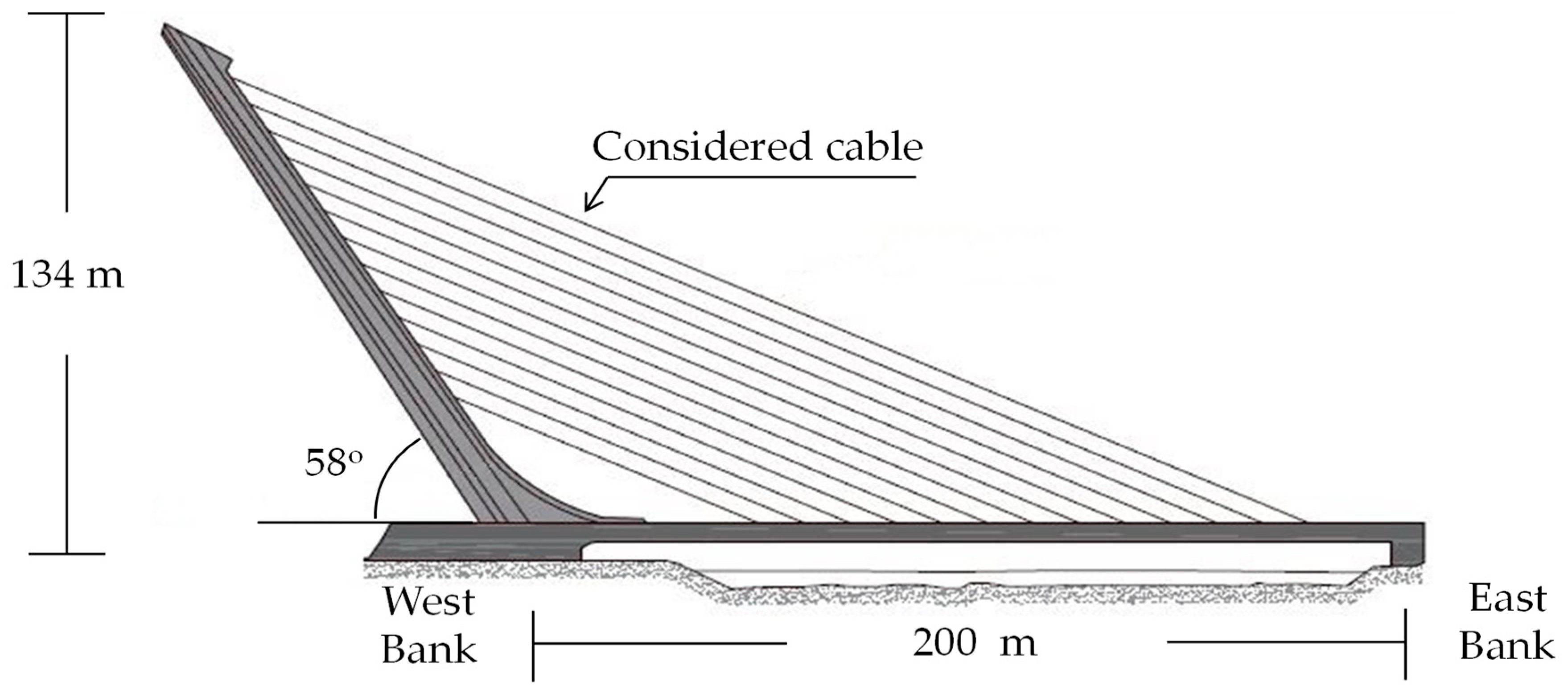
The deck of the cable-stayed bridge has a total length of 200 m, characterized by the absence of back-stays. Instead, the balance of forces is achieved through the inclination of the pylon of 32° to the vertical [45]. The pylon is connected to the deck by 13 pairs of stays separated by 12 m (Figure 4).
The dynamic experimental tests, performed on these cables in 2004 [31], show that the longest stay cables of this bridge, due to its low mass and damping ratio, were prone to vibrate under both the rain-wind induced excitation phenomenon and the turbulent wind action. Thus, this study is focused on controlling the dynamic response of one of these longest stay cables under both effects of the wind action (Figure 4).
For this purpose, the following step were performed: (i) a FE model of the cable has been performed; (ii) this model has been used to perform a numerical modal analysis of this structural element; (iii) the sensitivity of the considered cable to the wind-induced vibrations (rain-wind and turbulent effects) was analyzed based on the numerical modal parameters previously obtained; (iv) the dynamic response of the cable under wind action was determined through a transient dynamic analysis of the structure; (v) the compliance of the vibration serviceability limit state according to the recommendations of the FHWA guidelines [25] was checked; (vi); as this serviceability limit state was not met, three different passive damping devices were designed and implemented on the cable; and finally, (vii) the performance of the proposed method was validated comparing the results obtained by the proposed method against the values provided by the most used conventional design method [16].
In next sections the validation of the proposed method is described.
4.2. FE Model and Numerical Modal Analysis
A FE model of the cable was performed using the software package Ansys [32]. Initial stress effects, large strains and stress-stiffening conditions were considered. A mesh of 100 equal length elements was established. The geometrical and mechanical properties of the considered cable are shown in Table 2.
A numerical modal analysis was performed based on this FE model. As result of this analysis, the first six natural frequencies, , (Table 3) and associated vibration modes were obtained.
To validate the results provided by the FE model, the natural frequencies and vibrations modes of the considered cable have been determined analytically. For this purpose, the out-of-plane vibration, , of a rigidly supported cable with a small sag-to-length ratio may be obtained analytically through the solution of the following linearized equilibrium equation [10]:
where is the axial force of the cable (N) and is the mass per unit length of the cable (kg/m) (Table 2).
The solution of Equation (13) may be obtained by separation of variables [10]. In this manner, the out-of-plane vibration may be determined by the following expression:
where , is the vibration mode j of the cable, is the angular natural frequency of the vibration mode (rad/s) and is the total number of vibration modes considered.
The vibration mode may be expressed as follows [10]:
where is an arbitrary constant amplitude associated with the vibration mode and is the length of the cable (Table 2).
The angular natural frequency of the vibration mode considering the bending stiffness of the cable, , may be defined as [10]:
where is the Young’s modulus of the cable (Pa) and is the effective inertia moment of the cable (m4) (Table 2).
Equation (16) allows the analytical determination of the natural frequencies, , of the cable for out-of-plane vibrations. To analyze the effect of the bending stiffness on the natural frequencies of the cable, three different values of this magnitude have been considered in this study [10]: (i) non-bending stiffness (), (ii) 70% of bending stiffness (), and (iii) full-bending stiffness (). Table 3 shows the first six natural frequencies of the considered cable obtained analytically in terms of the bending stiffness.
As Table 3 reflects, the differences among the first six natural frequencies obtained numerically and analytically are small, and therefore, the FE model of the cable allows the adequate estimation of the response of this structural element under wind action.
On the other hand, as expected, the cable was prone to vibrate due to both the rain-wind induced vibrations (as the first six natural frequencies of the cable were lower than 3 Hz [25]) and the effect of turbulent wind action (as the first two natural frequencies of the cable were lower than 1 Hz [26]).
Although there are several proposals to determine the response of the stay cable during the occurrence of the rain-wind induced phenomenon [46], the most advanced guidelines [25,47] recommend avoiding this problem, ensuring that the damping ratios of all the vibration modes whose natural frequencies are lower than 3 Hz exceed a reference value. Concretely, the criterion established by the FHWA guidelines [25] has been considered herein. According to these guidelines, the condition to avoid the rain-wind induced vibrations phenomenon is to ensure that the Scruton number, , for all the considered vibration modes is greater than 10. This condition may be expressed as:
where is the damping ratio of the vibration mode .
According to the results of the mentioned dynamics test [31], the experimental damping ratios of the considered cable did not meet this condition, so the installation of a passive damper was recommended to increase the structural damping ratios of this cable.
Subsequently, the dynamic response of the cable under wind action was obtained in order to check the vibration serviceability limit state of the cable under the turbulent component of the wind action. If this serviceability limit state was not met, the passive damper must be designed to control the response of the cable under the two mentioned phenomena.
4.3. Transient Dynamic Analysis: Response of the Cable under Wind Action
In this manner, a transient dynamic analysis was performed to check the serviceability limit state of the cable. The dynamic response of the cable under turbulent wind forces was determined for this purpose. The non-linear geometrical behavior of the cable was considered.
Two steps must be given in order to obtain the dynamic response of the cable: (i) to determine the wind-induced forces generated by the wind action and (ii) to obtain the dynamic response of the cable through a transient dynamic analysis. Both steps are described in detail in next sections.
4.3.1. Wind-Induced Forces
To determine the wind-induced forces, the first step is to simulate numerically the wind velocity. For this purpose, the methodology described in the previous section about the numerical modelling of the damper-cable interaction model was implemented. Twelve simulations were generated with a duration, , of 300 s and a step time, , of 0.005 s, according to the recommendations of previous research [48]. In each numerical simulation, both the mean and fluctuating wind velocity were obtained at 10 different points of the cable (Figure 5). The cable has been divided into equal-length segments. The length of each segment was m. The following wind parameter were established to perform the numerical simulations: (i) a basic wind velocity, , 26 m/s, and (ii) an environment type III [27].
One simulation of the longitudinal, , and the transverse, , components of the wind velocity respectively, obtained via the application of the wave superposition spectral-based method [28,29], at point are shown in Figure 6a,b. In the case of the longitudinal direction, the mean wind velocity, , has been added.
Once the wind velocity was simulated, the wind-induced forces could be computed (Equations (4) and (5)). The following values were considered for the definition of the wind-induced forces: (i) the density of the air, kg/m3 [27]; the outer diameter of the cable, m [31]; the drag coefficient, [10]; and the lift coefficient [25].
One simulation of the drag, , and lift forces, , at the point is shown in Figure 7.
4.3.2. Dynamic Response of the Cable under Wind Action
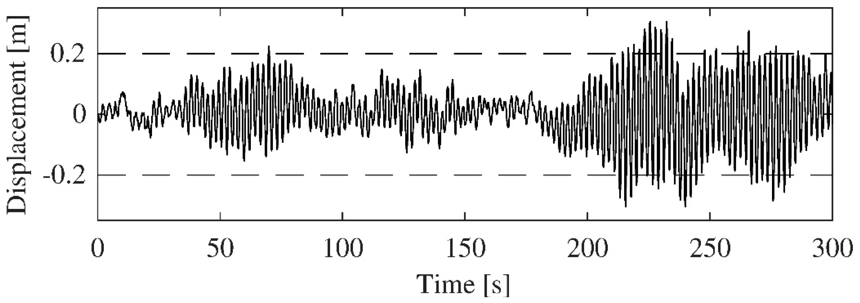
The previously calculated wind-induced forces were applied on the nodes of the FE model. A transient dynamic analysis was performed. From the results of this analysis, the evolution of the displacement at the middle point of the cable (of the most unfavorable simulation) is shown in Figure 8.
Finally, the vibration serviceability limit state of the cable was checked. For this purpose, the recommended design level, according to the FHWA guidelines [25], was established as a design criterion. As Table 1 shows, for this case, the maximum allowable displacement of the cable, , was 0.20 m. As Figure 8 shows, this cable does not meet the vibration serviceability limit state.
Thus, a passive damping device is recommended to be implemented in order to control the dynamic response of the cable under wind action considering both effects: rain-wind induced vibrations and the effect of the turbulent component of wind action.
In next section, three different types of passive damping devices were designed via the motion-based design method in order to mitigate the wind-induced vibrations in this cable. The results obtained were successfully compared with the values obtained based on a conventional design method [16].
4.4. Transient Dynamic Analysis: Response of the Damper-Cable Interaction Model under Wind Action
Each passive damping device is implemented at the point, . (Figure 1), according to the recommendations provided by Caetano [10] (with being the length of the cable (Table 2)). The design of the three passive damping devices was performed via the application of the proposed motion-based design method. The design process was implemented linking the software packages Ansys [32] (finite element analysis) and Matlab [30] (global optimization method).
To avoid ill-conditioning problems and to improve the performance of the design, a search domain was established for each characteristic parameter, . These search domains have been scaled for the sake of accuracy. A reference value has been established to scale the search domain of each characteristic parameter. Each reference value reduces the range of the search domain in order to improve the efficiency of the global optimization algorithm.
The following characteristic parameters were considered as design variables of each passive damping device: (i) for the viscous damper, ; (ii) for the elastomeric damper, ; and (iii) for the friction damper, .
First, the search domain of the design parameter, , was established according to the following rules: (i) as the lower bound of the search domain, (being (sN/m) the minimum value of the damping coefficient of the passive damping device and (sN/m) a reference value for scaling), the minimum structural damping ratio of the cable, (being the considered vibration mode, ), recommended by the FHWA guidelines [25] to avoid the rain-wind induced vibrations was considered; and (ii) as the upper bound of the search domain, (being (sN/m) the maximum value of the damping coefficient of the passive damping device), the optimum value obtained via the application of the conventional design method proposed by Pacheco [16] was taken into account. As a reference value, sN/m, was established in order to reduce the range of the search domain.
To determine the equivalent damping ratio of the mode of the cable, (−), in terms of the damping coefficient of the damper, the analytical expression proposed by Krenk et al. [18] has been used. This relationship may be defined as follows:
where ; is the mass per unit length of the cable; and is the first angular natural frequency of the cable (rad/s).
The first six vibration modes were considered (Table 3) to establish the search domain of this design parameter. In this manner, the lower bound of this search domain, , was established via the application of Equations (17) and (18) to the six considered vibration modes.
On the other hand, the upper bound of this search domain, , was determined via the optimum damping coefficient, , of the Pacheco’s curve [16]. The following expression may be used to obtain its value.
Thus, the upper bound of this search domain, , was established via the application of Equation (19) to the six considered vibration modes.
It is necessary to point out that the search domain of this design parameter, , ensures that if a solution (design) is found by the motion-based design algorithm, the rain-wind induced vibrations phenomenon is avoided, and this solution improves the values with respect to those proposed by the most used conventional design method, the Pacheco’s curve [16].
Second, the search domain of the design parameter, , was established based on the analysis of the results provided by previous research [10]. According to these results, the following search domain was established: (i) as the lower bound, was considered (with (N/m) being the minimum value of the stiffness coefficient of the passive damping device and (N/m) a reference value for scaling); and as the upper bound, was taken into account (with (N/m) being the maximum value of the stiffness coefficient of the passive damping device). As a reference value, N/m was established in order to reduce the range of the search domain.
Finally, the search domain of the design parameter, , was established again via the results provided by previous research [10]. According to these results, the following search domain was established: (i) as the lower bound, was considered (with (N) being the minimum value of the friction force of the passive damping device and (N) a reference value for scaling); and as the upper bound, was taken into account (with (N) being the maximum value of the friction force of the passive damping device). As a reference value, N was considered in order to reduce the range of the search domain.
The motion-based design of the three considered passive damping devices is described in the next sections. As the design criterion, the compliance of the vibration serviceability limit state was considered. The recommendations of the FHWA guidelines [25] were assumed for this purpose.
4.4.1. Motion-Based Design of the Viscous Damper
The motion-based design of the viscous damper may be formulated as:
As an optimization method, genetic algorithms were considered. A population of 20 individuals (vectors), a maximum number of iterations of 50, and a tolerance value of for the variation of the multi-objective function were established.
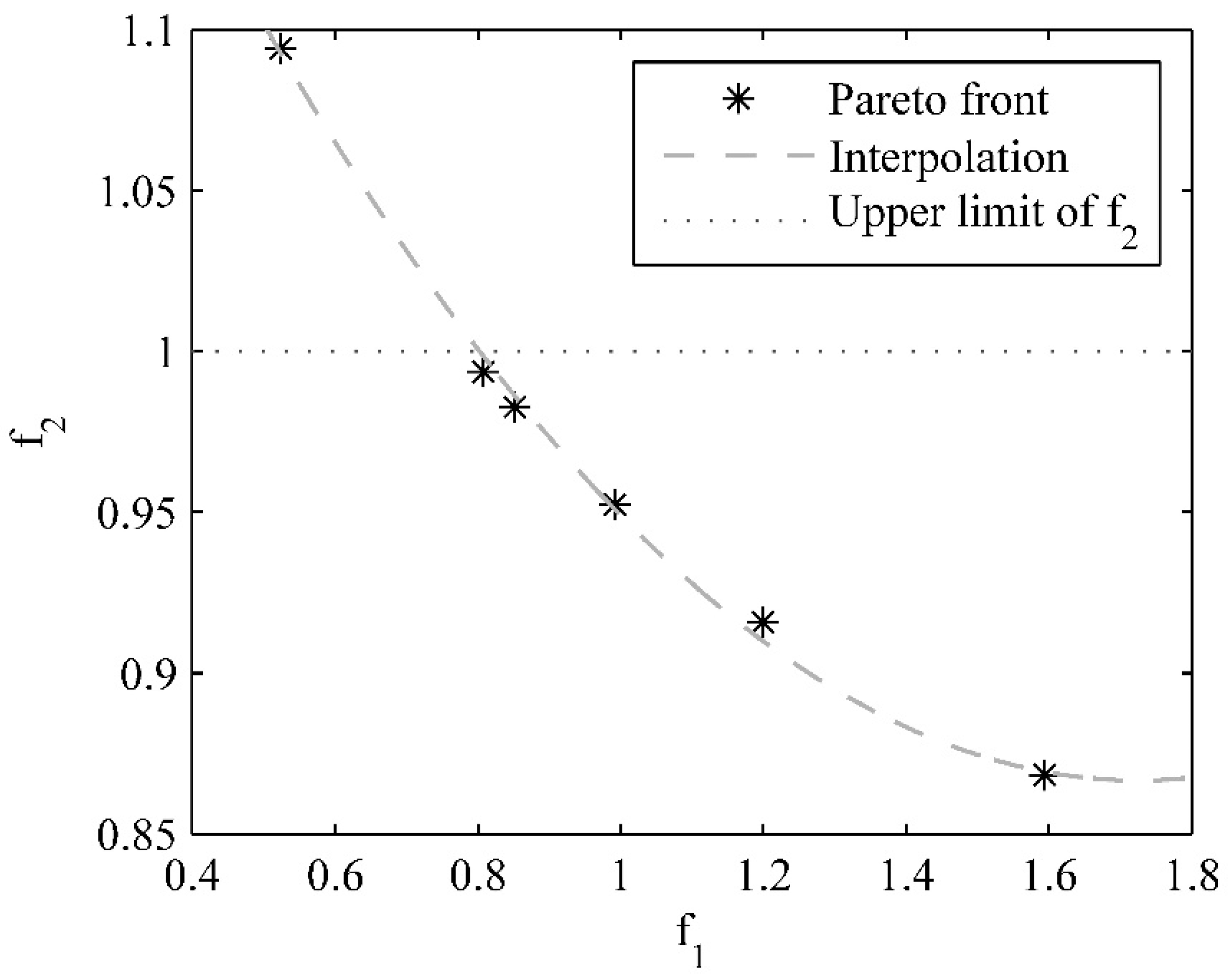
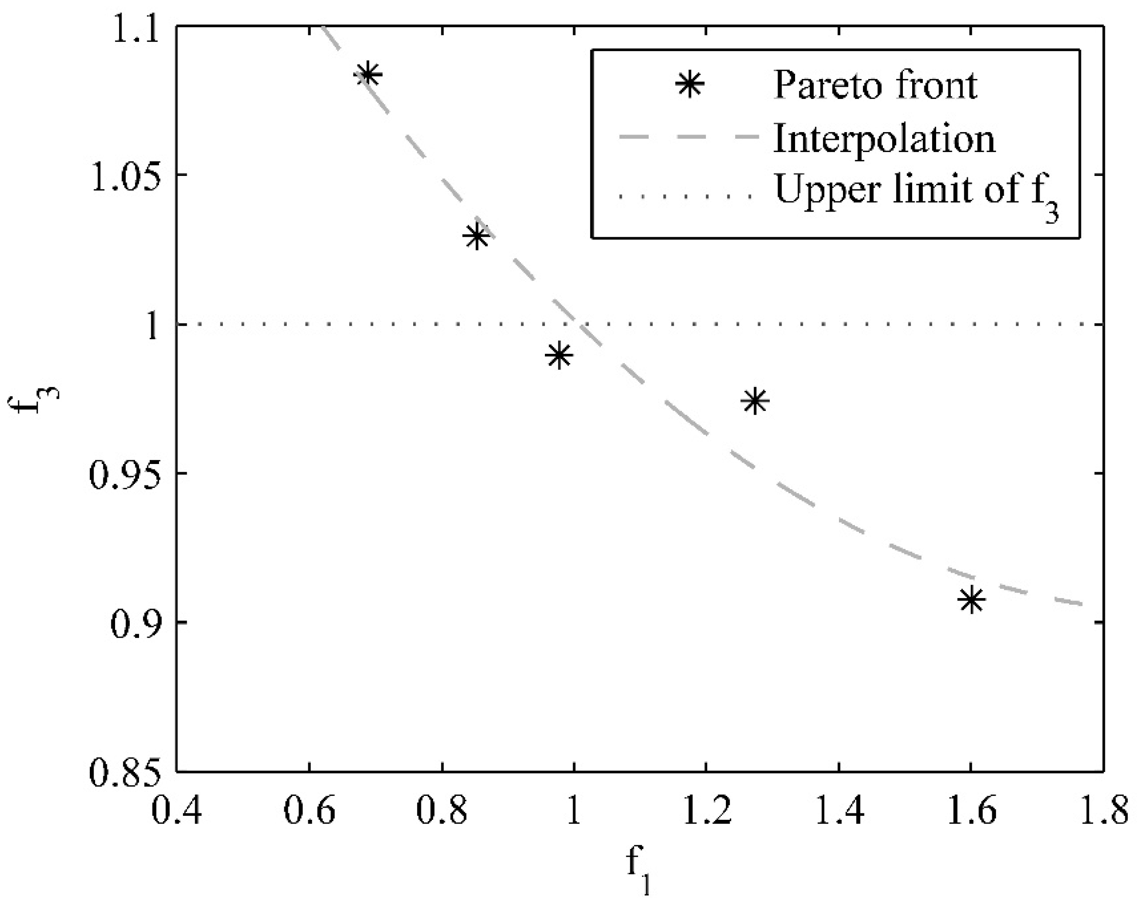
As a result of this problem, the value of the design variable, , was obtained. Figure 9 shows the Pareto front of the multi-objective function, , where the relation between and is illustrated. The limit of the additional condition, , has also been included as reference (upper limit of ). The points of the Pareto front may be fitted by a second-order polynomial (Figure 9). The optimal value of the design variable obtained was, sN/m.
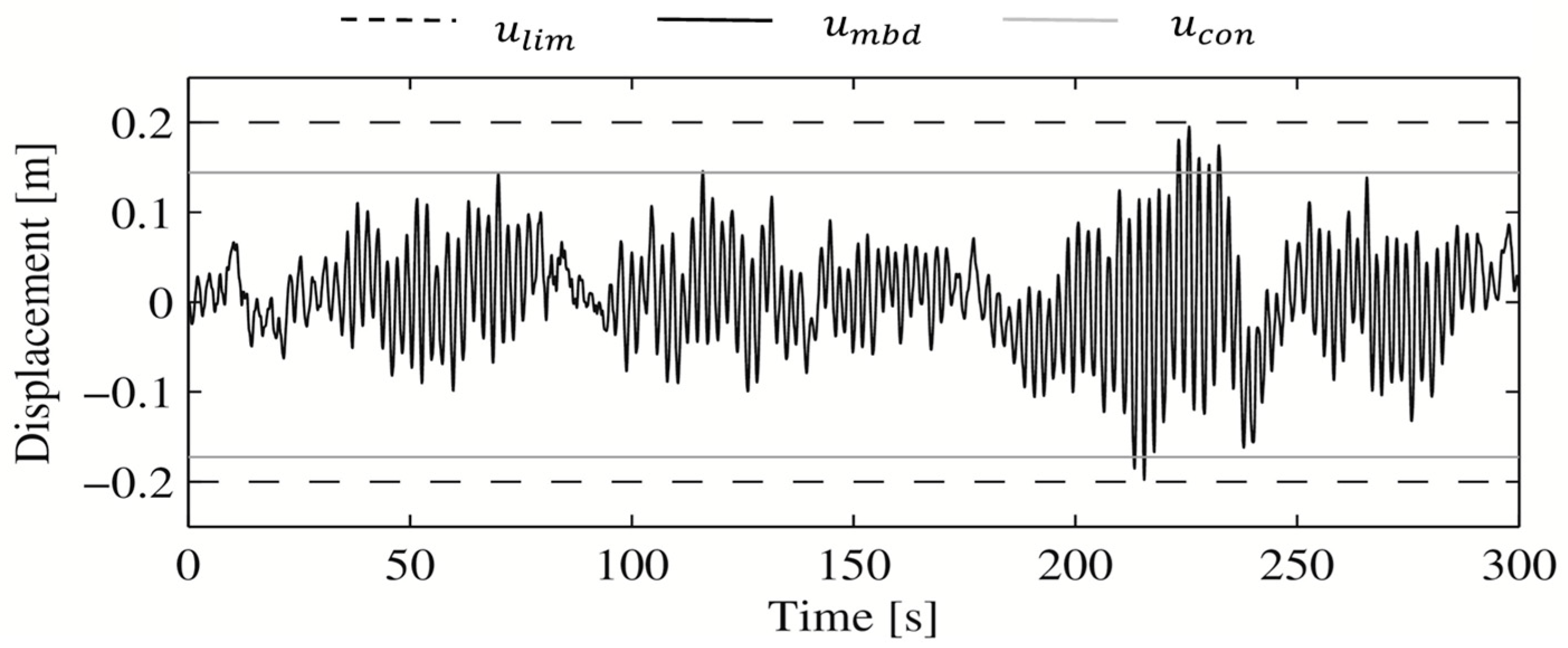
Figure 10 shows the displacement at the mid-span of the cable with the viscous damper designed according to the motion-based design method, (the most unfavorable simulation). The maximum displacement at the mid-span of the cable with the viscous damper designed according to the conventional design method [16] has also been included, . Additionally, the design criterion, , (vibration serviceability limit state) was also included as reference.
4.4.2. Motion-Based Design of the Elastomeric Damper
The motion-based design of the elastomeric damper may be formulated as:
As an optimization method, genetic algorithms were used again. The same parameters from the previous case were considered for the characterization of the optimization algorithm.
As a result of this problem, the values of the design variables, and , were obtained. Figure 11 shows the Pareto front of the two components of the multi-objective function, . The relation between and is illustrated. The limit of the additional condition, , has been also included as reference (upper limit of ). The points of the Pareto front may be fitted by a second-order polynomial (Figure 11). The optimal value of the design variables obtained was, sN/m and N/m.
Figure 12 shows the displacement at the mid-span of the cable with the elastomeric damper designed according to the motion-based design method, (the most unfavorable simulation). Additionally, both the maximum displacement at the mid-span of the cable with the viscous damper designed according to the conventional design method [16], , and the design criterion, , were also included as references.
4.4.3. Motion-Based Design of the Friction Damper
The motion-based design of the friction damper may be formulated as:
As in the previous cases, the same optimization algorithm was considered.
As a result of this problem, the value of the design variables, , , and ,was obtained. Figure 13 shows the Pareto front of the two components of the multi-objective function, . The relation between and is illustrated. The limit of the additional condition, , has also been included as reference (upper limit of ). The points of the Pareto front may be fitted by a second-order polynomial (Figure 13). The optimal value of the design variables obtained was, sN/m, N/m and N.
Figure 14 shows the displacement at the mid-span of the cable with the friction damper designed according to the motion-based design method, (the most unfavorable simulation). Both the maximum displacement at the mid-span of the cable with the viscous damper designed according to the conventional design method [16], , and the design criterion, , have also been included as references.
4.5. Discussion of the Results
To sum up, Table 4 shows a summary of the characteristic parameters of the considered passive damping devices obtained through the application of both the conventional [16] and the motion-based design method.
As Figure 9, Figure 11 and Figure 13 show, the motion-based design algorithm found a solution, which by minimizing the value of the characteristic parameters of each passive damping devices, met the design criterion established according the FHWA guidelines [25].
On the other hand, as Figure 10, Figure 12 and Figure 14 show, the motion-based design algorithm makes it possible to better adjust the response of the cable to the design criterion, improving the cost-effectiveness ratio of the three considered passive damping devices.
As the proposed design for each passive damping device is within the established search domain, the results provided by the proposed method improve the values obtained via the most usual conventional design method [16]. The reduction of the characteristic parameters is reflected in both a reduction of the cost and the size of the damper, making the installation process easier as consequence.
Thus, as shown in this study, the proposed design method allows the design of different types of passive damping devices to mitigate wind-induced vibrations in stay cables through a unique general algorithm.
Finally, for the case under study, the viscous damper seems to be the best option in order to control the dynamic response of this cable under both the rain-wind induced and turbulent effects of the wind action. The minimum value of the damping coefficient was obtained for this type of passive control device.
For all these reasons, the motion-based design method has been validated as a valuable tool for the design of passive damping devices in order to mitigate the wind-induced vibrations in stay cables.
5. Conclusions
Wind-induced excitation may produce large displacements of the stay cables of bridges. To overcome this problem, different types of passive damping devices may be usually installed to mitigate the wind-induced vibrations. In this study, a motion-based design method has been proposed and implemented in order to design optimally three different types of passive damping devices (viscous, elastomeric and friction damper) in order to mitigate wind-induced vibrations in the stay cables of bridges. The proposed method transforms the design problem into an optimization problem. The main objective of the optimization problem is to minimize a multi-objective function considering as design variables the characteristic parameters of each considered damping device. The multi-objective function is defined in terms of the scaled characteristic parameters of the considered passive damping device, one single-function for each parameter, and an additional function that takes into account the compliance of the considered design criterion. Genetic algorithms have been considered as optimization method. The design criterion has been established according to the recommendations of the FHWA guidelines. The maximum displacement of the cable under wind action was limited according to this design criterion. A search domain was established for each design variable. As result of the optimization process, different Pareto fronts were obtained. The analysis of these Pareto fronts allows the finding of an optimal design for each passive damping device, in which the minimization of its characteristic parameter meets the considered design criterion.
Finally, in order to validate the performance of the proposed method, a real cable-stayed bridge, the Alamillo bridge (Seville, Spain), was considered as a benchmark. The dynamic response of one of its longest stay cables under wind action has been controlled via the implementation of the three mentioned passive damping devices independently. The characteristic parameters of each passive damping device were determined via the implementation of the proposed design method. Both effects, the turbulent component of the wind action and the rain-wind-induced phenomenon, have been considered. Nevertheless, the proposed method can be applied to mitigate the wind-induced vibrations in stay cables originating from other phenomena (vortex shedding, etc.). The wind action was simulated based on the recommendations of the European standards.
For this purpose, the following steps were taken: (i) a FE model of the cable was built; (ii) twelve temporal simulations of the turbulent component of the wind action were generated at ten different heights of the cable, (iii) the drag and lift forces were determined taking into account both the mean wind velocity and the fluctuating velocity associated with the turbulent components; (iv) both a numerical modal and transient dynamic analysis were performed in order to obtain the natural frequencies and the response of the cable under the wind action; (v) the compliance of the design criterion with the guidelines established by the FHWA was checked; (vi) as the design criterion was not met, three different passive damping devices were designed and installed; and (vii) the characteristic parameters of each passive damping device were determined via the application of the proposed motion-based design method. The design process was repeated for each considered passive damping device. The results provided by the proposed method have been compared successfully with the designs obtained according to the most usual conventional design method. The use of the proposed method involves two advantages: (i) the reduction of the characteristic parameters of each passive damping device, reducing their cost and size and making easier its installation; and (ii) this method allows addressing the problem of designing a passive control system in a generalized way, applying the same methodology regardless of the type of passive damping device used.
On the other hand, the results of the optimization show a similar value of the damping coefficient for the three considered damping devices. According to this, the dashpot is shown as the most efficient tool to mitigate the wind-induced vibrations in stay cables of bridges.
Finally, further studies should be carried out in order to validate experimentally the performance of passive damping devices, designed according to the proposed method, to control the dynamic response of cable-stayed bridges under wind action.
Author Contributions
Conceptualization, J.F.J.-A. and A.S.; Methodology, J.F.J.-A.; Programming, J.N.-P. and J.J.-M.; Validation, J.F.J.A. and A.S.; Writing-Original Draft Preparation, J.N.-P.; Writing-Review & Editing, J.F.J.-A.; Funding Acquisition, A.S.
Funding
This research was funded by the Ministerio de Economía y Competitividad of Spain and the European Regional Development Fund under project DPI2014-53947-R. The research contract from the Universidad de Sevilla Ref: USE-17047-G supported J. Naranjo-Pérez.
Conflicts of Interest
The authors declare no conflict of interest.
References
- Wianecki, J. Cables Wind Excited Vibrations of Cable-Stayed Bridges. In Proceedings of the 5th International Conference of Wind Engineering, Fort Collins, CO, USA, 8–14 July 1979; pp. 1381–1393. [Google Scholar]
- Stiemer, S.; Taylor, P.; Vincent, D. Full Scale Dynamic Testing of the Annacis Bridge. IABSE Periodica 1988, 394, 1–16. [Google Scholar]
- Domaneschi, M.; Martinelli, L.; Po, E. Control of wind buffeting vibrations in a suspension bridge by TMD: Hybridization and robustness issues. Comput. Struct. 2015, 155, 3–17. [Google Scholar] [CrossRef]
- El Ouni, M.; Ben Kahla, N.; Preumont, A. Numerical and experimental dynamic analysis and control of a cable-stayed bridge under parametric excitation. Eng. Struct. 2012, 45, 224–256. [Google Scholar] [CrossRef]
- Pakos, W.; Wójcicki, Z. Vibration control of a cable-stayed footbridge using the tension changes of cable. Procedia. Eng. 2014, 91, 142–147. [Google Scholar] [CrossRef]
- Crusells-Girona, M.; Aparicio, A.C. Active control implementation in cable-stayed bridges for quasi-static loading patterns. Eng. Struct. 2016, 118, 394–406. [Google Scholar] [CrossRef]
- Zhou, H.J.; Sun, L.M. Damping of stay cable with passive-on magnetorheological dampers: A full-scale test. Int. J. Civ. Eng. 2013, 11, 154–159. [Google Scholar]
- Yeganeh Fallah, A.; Attari, N.K.A. Robust control of seismically excited cable stayed bridges with MR dampers. Smart Mater. Struct. 2017, 26, 035056. [Google Scholar] [CrossRef]
- Zhou, H.J.; Huang, X.G.; Xiang, N.; He, J.W.; Sun, L.M.; Xing, F. Free Vibration of a Taut Cable with a Damper and a Concentrated Mass. Struct. Control Health Monit. 2018, 25, e2251. [Google Scholar] [CrossRef]
- Caetano, E. Cable Vibrations in Cable-Stayed Bridges; IABSE: Zürich, Switzerland, 2007. [Google Scholar]
- Ito, M.; Fujino, Y.; Miyata, T.; Narita, N. Cable-stayed bridges: Recent Developments and Their Future, 1st ed.; Elsevier Science Ltd.: Amsterdam, The Netherland, 1991; p. 448. ISBN 978-0444890559. [Google Scholar]
- Xu, Y.L.; Zhou, H.J. Damping cable vibration for a cable-stayed bridge using adjustable fluid dampers. J. Sound Vib. 2007, 306, 349–360. [Google Scholar] [CrossRef]
- Domaneschi, M.; Martinelli, L. Optimal passive and semi-active control of a wind excited suspension bridge. Struct. Infrastruct. E 2013, 9, 242–259. [Google Scholar] [CrossRef]
- Domaneschi, M.; Martinelli, L. Refined optimal passive control of buffeting-induced wind loading of a suspension bridge. Wind Struct. 2014, 18, 1–20. [Google Scholar] [CrossRef]
- Kovacs, I. Zur Frage der Seilschwingungen und der Seildämpfung. Bautechnik 1982, 10, 325–332. [Google Scholar]
- Pacheco, B.M.; Fujino, Y.; Sulekh, A. Estimation curve for modal damping in stay cables with viscous damper. J. Struct. Eng. ASCE 1993, 119, 1961–1979. [Google Scholar] [CrossRef]
- Yoneda, M.; Maeda, K. A study on practical estimation method for structural damping of stay cables with dampers. Doboku Gakkai Ronbunshu 1989, 1989, 455–458. [Google Scholar] [CrossRef]
- Krenk, S. Vibrations of a taut cable with an external damper. J. Appl. Mech. 2000, 67, 772–776. [Google Scholar] [CrossRef]
- Mehrabi, A.; Tabatabai, H. Unified finite difference formulation for free vibration of cables. J. Struct. Eng. ASCE 1998, 124, 1313–1322. [Google Scholar] [CrossRef]
- Hoang, N.; Fujino, Y. Analytical study on bending effects in a stay cable with a damper. J. Eng. Mech. ASCE 2007, 133, 1241–1246. [Google Scholar] [CrossRef]
- Cheng, S.; Darivandi, N.; Ghrib, F. The design of an optimal viscous damper for a bridge stay cable using energy-based approach. J. Sound Vib. 2010, 329, 4689–4704. [Google Scholar] [CrossRef]
- Connor, J.J. Introduction to Structural Motion Control, MIT-Prentice Hall Series on Civil, Environmental and Systems Engineering; Prentice Hall: Bergen, NJ, USA, 2003. [Google Scholar]
- Jiménez-Alonso, J.F.; Sáez, A. Robust Optimum Design of Tuned Mass Dampers to Mitigate Pedestrian-Induced Vibrations Using Multi-Objective Genetic Algorithms. Struct. Eng. Int. 2017, 27, 492–501. [Google Scholar] [CrossRef]
- Ontiveros-Pérez, S.; Fadel Miguel, L.; Fadel Miguel, L. Robust Simultaneous Optimization of Friction Damper for the Passive Vibration Control in a Colombian Building. Procedia Eng. 2017, 199, 1743–1748. [Google Scholar] [CrossRef]
- Wind-Induced Vibration of Stay Cables; Publication Number FHWA-HRT-05-083; Federal Highway Administration: New York, NY, USA, August 2007.
- Simiu, E.; Scanlan, R.H. Wind Effects on Structures: Fundamentals and Applications to Design, 3rd ed.; John Willey&Sons, Inc.: New York, NY, USA, 1996. [Google Scholar]
- EN 1991-1-4 Eurocode 1: Actions on Structures. Wind Actions. 2005. Available online: https://www.icevirtuallibrary.com/doi/book/10.1680/dgte1.31524 (accessed on 4 June 2018).
- Cremona, C.; Foucriata, J.C. Comportement au vent des ponts. Presses de l’ecole natinale des Ponts et chaussées; Association Francaise de Génie Civil: Paris, France, 2002; ISBN 2-85978-360-1. [Google Scholar]
- Jurado Camacho, D. Simulación Estocástica de Cargas para análisis dinámico de estructuras en Ingeniería Civil. Master’s Thesis, Universidad de Sevilla, Sevilla, Spain, 2017. [Google Scholar]
- Matlab R2018a. Available online: http://www.mathworks.com/ (accessed on 4 June 2018).
- Casas, J.; Aparicio, A. Rain–wind-induced cable vibrations in the Alamillo cable-stayed bridge (Sevilla, Spain). Assessment and remedial action. Struct. Infrastruct. E 2010, 6, 549–556. [Google Scholar] [CrossRef] [Green Version]
- Ansys Mechanical Release 19. Available online: http://www.ansys.com/ (accessed on 4 June 2018).
- Connor, J.; Laflamme, S. Optimal Passive Damping Distribution. In Structural Motion Engineering; Springer: New York, NY, USA, 2014; pp. 141–197. ISBN 978-3-319-06281-5. [Google Scholar]
- Zhou, H.; Sun, L.; Xing, F. Damping of full-scale stay cable with viscous damper: experiment and analysis. Adv. Struct. Eng. 2014, 17, 265–274. [Google Scholar] [CrossRef]
- Xu, Z.; Shen, Y.; Zhao, H. A synthetic optimization analysis method on structures with viscoelastic dampers. Soil Dyn. Earthq. Eng. 2003, 23, 683–689. [Google Scholar] [CrossRef]
- Zhou, H.J.; Sun, L.M.; Xing, F. Free vibration of taut cable with a damper and a spring. Struct. Control Health Monit. 2014, 21, 996–1014. [Google Scholar] [CrossRef]
- VSL. Damping Systems for Stay Cables. VSL International LTD. 2013. Available online: http://www.vsl.com/business-lines/systems-and-technologies/damping-systems-for-stays.html (accessed on 4 June 2018).
- Seong, J.; Min, K. An analytical approach for design of a structure equipped with friction dampers. Procedia Eng. 2011, 14, 1245–1251. [Google Scholar] [CrossRef]
- Davenport, A.G. The dependence of wind load upon meteorological parameters. Wind Effects Build. Struct. 1968, 19–82. Available online: https://ci.nii.ac.jp/naid/10004749178/ (accessed on 4 June 2018).
- Hong, S. Time Domain Buffeting Analysis of Large-Span Cable-Stayed Bridge. Master’s Thesis, Universidade do Porto, Porto, Portugal, 2009. [Google Scholar]
- Solari, G. Gust-Excited Vibrations. In Wind-Excited Vibrations of Structures; Sockel, H., Ed.; International Centre for Mechanical Sciences; Springer: Vienna, Austria, 1994. [Google Scholar]
- Liang, Q. Performance-based optimization: A review. Adv. Struct. Eng. 2007, 10, 739–753. [Google Scholar] [CrossRef]
- Wright, S.; Nocedal, J. Numerical Optimization; Springer Verlag: New York, NY, USA, 1999; ISBN 0-387-98793-2. [Google Scholar]
- Mitchell, M. An introduction to genetic algorithms. In Complex Adaptative Systems; MIT Press: Cambridge, MA, USA, 1998. [Google Scholar]
- Casas, J.; Aparicio, A. Monitoring of the Alamillo cable-stayed bridge during construction. Exp. Mech. 1998, 38, 24–28. [Google Scholar] [CrossRef]
- Zhou, H.J.; Xu, Y.L. Wind-rain-induced vibration and control of stay cables in a cable-stayed bridge. Struct. Control Health Monit. 2007, 14, 1013–1033. [Google Scholar] [CrossRef]
- EN 1993-1-11 Eurocode 3–Design of Steel Structures, Part 1–11: Design of Structures with Tension Components. 2006. Available online: https://en.wikipedia.org/wiki/Eurocode_3:_Design_of_steel_structures (accessed on 4 June 2018).
- Park, S.; Bosch, H.R. Mitigation of Wind-Induced Vibration of Stay Cables: Numerical Simulations and Evaluations; Federal Highway Administration: Hampton, VA, USA, August 2014.
Figure 1.
Numerical model of the damper-cable interaction model for the three considered dampers. (a) viscous damper; (b) elastomeric damper, and (c) friction damper.
Figure 1.
Numerical model of the damper-cable interaction model for the three considered dampers. (a) viscous damper; (b) elastomeric damper, and (c) friction damper.

Figure 2.
Reference coordinate system, components of wind velocity and drag and lift force components.
Figure 2.
Reference coordinate system, components of wind velocity and drag and lift force components.

Figure 3.
Flowchart of the motion-based design method for the design of passive damping devices.

Figure 4.
Lateral view of the Alamillo bridge.

Figure 5.
Different point () where turbulent wind action has been simulated.

Figure 6.
One wind velocity simulation generated at according to the wave superposition spectral-based method [28,29]: (a) longitudinal direction; (b) transverse direction.


Figure 7.
Wind-induced forces at the point . (a) Drag force, and (b) lift force.

Figure 8.
Displacement at the mid-span of the considered cable under wind action.

Figure 9.
Pareto front where is a scaled value of the damping coefficient, , ( sN/m) and .

Figure 10.
Displacement of the cable at the mid-span with the viscous damper designed according to the motion-based design method.
Figure 10.
Displacement of the cable at the mid-span with the viscous damper designed according to the motion-based design method.

Figure 11.
Pareto front where is a scaled value of the damping coefficient, , ( sN/m) and .

Figure 12.
Displacement of the cable at the mid-span with the elastomeric damper designed according to the motion-based design method.
Figure 12.
Displacement of the cable at the mid-span with the elastomeric damper designed according to the motion-based design method.

Figure 13.
Pareto front where is a scaled value of the damping coefficient, , ( sN/m) and .

Figure 14.
Displacement of the cable at the mid-span with the friction damper designed according to the motion-based design method.
Figure 14.
Displacement of the cable at the mid-span with the friction damper designed according to the motion-based design method.


Table 1.
User tolerance limits for cable displacement, , in terms of the outer diameter of the cable, (m), for different design levels according to the FHWA guidelines [25].
Table 1.
User tolerance limits for cable displacement, , in terms of the outer diameter of the cable, (m), for different design levels according to the FHWA guidelines [25].
| Design Levels | (m) |
|---|---|
| Preferred | |
| Recommended | |
| Not to exceed |
Table 2.
Mechanical and geometrical properties of the considered cable.
| Cable | Value |
|---|---|
| Length of the cable, , (m) | 292 |
| Effective area, , (m2) | |
| Effective inertia moment, , (m4) | |
| Mass per unit length, , (kg/m) | 60 |
| Initial axial force, (N) | |
| Young’s modulus, , (Pa) | |
| Outer diameter, , (m) | 0.20 |
| Angle with the deck, , (°) | 26 |
Table 3.
First six numerical and analytical natural frequencies (considering different contribution of the bending stiffness) of the considered cable ( with the considered vibration mode).
Table 3.
First six numerical and analytical natural frequencies (considering different contribution of the bending stiffness) of the considered cable ( with the considered vibration mode).
| Element | (Hz) | (Hz) | (Hz) | (Hz) | (Hz) | (Hz) |
|---|---|---|---|---|---|---|
| Finite element method | 0.4491 | 0.8984 | 1.3479 | 1.7979 | 2.2485 | 2.6998 |
| Analytical method () | 0.4491 | 0.8982 | 1.3473 | 1.7963 | 2.2454 | 2.6945 |
| Analytical method () | 0.4503 | 0.9006 | 1.3509 | 1.8012 | 2.2515 | 2.7019 |
| Analytical method () | 0.4505 | 0.9011 | 1.3516 | 1.8022 | 2.2527 | 2.7033 |
Table 4.
Characteristic parameters of the three considered passive damping devices according to both the conventional [16] and the proposed motion-based design method.
Table 4.
Characteristic parameters of the three considered passive damping devices according to both the conventional [16] and the proposed motion-based design method.
| Design Method | Damper | (sN/m) | (N/m) | (N) |
|---|---|---|---|---|
| Conventional | Viscous | 164,000 | - | - |
| Motion-based | Viscous | 80,710 | - | - |
| Motion-based | Elastomeric | 97,740 | 103,180 | - |
| Motion-based | Friction | 92,250 | 79,320 | 38,690 |
© 2018 by the authors. Licensee MDPI, Basel, Switzerland. This article is an open access article distributed under the terms and conditions of the Creative Commons Attribution (CC BY) license (http://creativecommons.org/licenses/by/4.0/).
Share and Cite
MDPI and ACS Style
Naranjo-Pérez, J.; Jiménez-Manfredi, J.; Jiménez-Alonso, J.F.; Sáez, A. Motion-Based Design of Passive Damping Devices to Mitigate Wind-Induced Vibrations in Stay Cables. Vibration 2018, 1, 269-289. https://doi.org/10.3390/vibration1020019
AMA Style
Naranjo-Pérez J, Jiménez-Manfredi J, Jiménez-Alonso JF, Sáez A. Motion-Based Design of Passive Damping Devices to Mitigate Wind-Induced Vibrations in Stay Cables. Vibration. 2018; 1(2):269-289. https://doi.org/10.3390/vibration1020019
Chicago/Turabian StyleNaranjo-Pérez, Javier, Javier Jiménez-Manfredi, Javier F. Jiménez-Alonso, and Andrés Sáez. 2018. "Motion-Based Design of Passive Damping Devices to Mitigate Wind-Induced Vibrations in Stay Cables" Vibration 1, no. 2: 269-289. https://doi.org/10.3390/vibration1020019