
Study on the Mechanism and Suppression of Harmonic Vibration of AMB-Rotor System

1
Aviation Engineering School, Air Force Engineering University, Xi’an 710043, China
2
Science and Technology on Space Physics Laboratory, Beijing 100076, China
*
Author to whom correspondence should be addressed.
Vibration 2024, 7(1), 83-97; https://doi.org/10.3390/vibration7010005
Submission received: 27 November 2023
/
Revised: 6 December 2023
/
Accepted: 16 January 2024
/
Published: 18 January 2024
Abstract
:The AMB-rotor system is complex and has strong coupling characteristics, which allows multi-harmonic disturbances to enter the system through different ways to produce vibrations with rich spectrum components, which has a great influence on the improvement of micro-vibration accuracy of the rotor system. To further achieve active control of the micro-vibration in the AMB-rotor system, firstly, the mechanism of multi-source disturbance is analyzed according to the working principle of the AMB-rotor system, and the mathematical and physical relationship between the mechanism of disturbance generation and the inducement is deeply studied. Then, the structure of a novel adaptive notch filter, the method of adaptive frequency estimation and analysis of harmonic current suppression in the AMB system are presented. Finally, simulation and experimental research using an MSCMG system demonstrate the feasibility of the proposed method regarding the elimination of harmonic control current.
1. Introduction
With the development of the times, the new generation of Earth observation satellites and the new generation of agile mobile satellites are in urgent need of “ultra-stable and ultra-static” satellite platforms with micro-vibration characteristics [1]. The vibration caused by the high-speed rotating components in inertial actuators such as control moment gyroscopes (CMGs) and flywheels is an important factor that determines the stability of a satellite platform and further improves the comprehensive performance of space payloads [2].
The rotor of a magnetically suspended control moment gyroscope (MSCMG) is suspended by active magnetic bearings (AMBs) and can be controlled. It has a lot of advantages, such as long service life, high accuracy and micro-vibration. It is a new type of attitude control actuator for spacecraft [3,4,5]. Because the internal AMB-rotor rotates at a high speed, multi-source disturbances enter the AMB-rotor system through different ways, generating vibration forces with rich spectral components [6]. There are many factors that can cause multi-source disturbances, such as uncertainty, time delay characteristics, noise interference and so on. But multi-source disturbances are mainly induced by the rotor residual unbalance and sensor runout (SR).
The rotor residual unbalance is the capital disturbance source in the operation of MSCMG [7]. Machining errors and uneven material inevitably make the rotor unbalanced. Usually, a dynamic balancing machine is applied firstly for balancing the rotor [8]. However, because dynamic balancing lacks precision, residual unbalance remains, which will generate an unbalanced vibration force [9]. Scholars use different control methods to suppress unbalanced vibration forces, such as LMS feedforward compensation [10], a notch filter [11], the Fourier coefficient method [12], an adaptive filter [13], etc.
SR is also known as a displacement sensor error. It is mainly caused by the electrical and mechanical non-ideal characteristics of the sensor. Among them, the electrical non-ideal characteristics mainly regard residual magnetic non-uniformity, while the mechanical non-ideal characteristics include material non-uniformity and the surface of the displacement sensor not being round enough. These factors cause AMB-rotor displacement and harmonic disturbance through the feedback loop which generates a harmonic vibration force. In 1997, the authors of [14] firstly considered the displacement sensor error in the AMB control system and pointed out that the amplitude of harmonic disturbance caused by SR is independent of the rotation speed. The authors of [15] established a magnetically suspended rotor dynamics model with SR and studied the influence of parameter perturbation on the model. The displacement negative stiffness vibration force can be ignored, so the vibration suppression methods have been researched to only reduce the harmonic current, such as repetitive control [16,17], multi resonance controller [18,19], multi synchronous rotation coordinate transformation [20,21] and so on. However, these methods either require a large amount of computation and are not suitable for engineering applications, or do not consider system stability throughout the entire speed range, or they need the rotational speed information.
Combined with the working principle of the AMB-rotor system in MSCMG, this paper researches the influence of residual unbalance and SR on the control system, and proposes an improved adaptive notch filter for harmonic sinusoidal signals with adaptive frequency estimation to decrease the harmonic control current in the AMB-rotor system while ensuring system stability.
The article is organized as follows. The mechanisms of residual unbalance and SR generation in the AMB-rotor system are analyzed in Section 2. The structure of the adaptive notch filter, adaptive frequency estimation method and the analysis of harmonic current suppression in the AMB system are presented in Section 3. Section 4 is devoted to simulation and experimental research. Section 5 gives the conclusion.
2. Analysis of Harmonic Vibration Mechanism
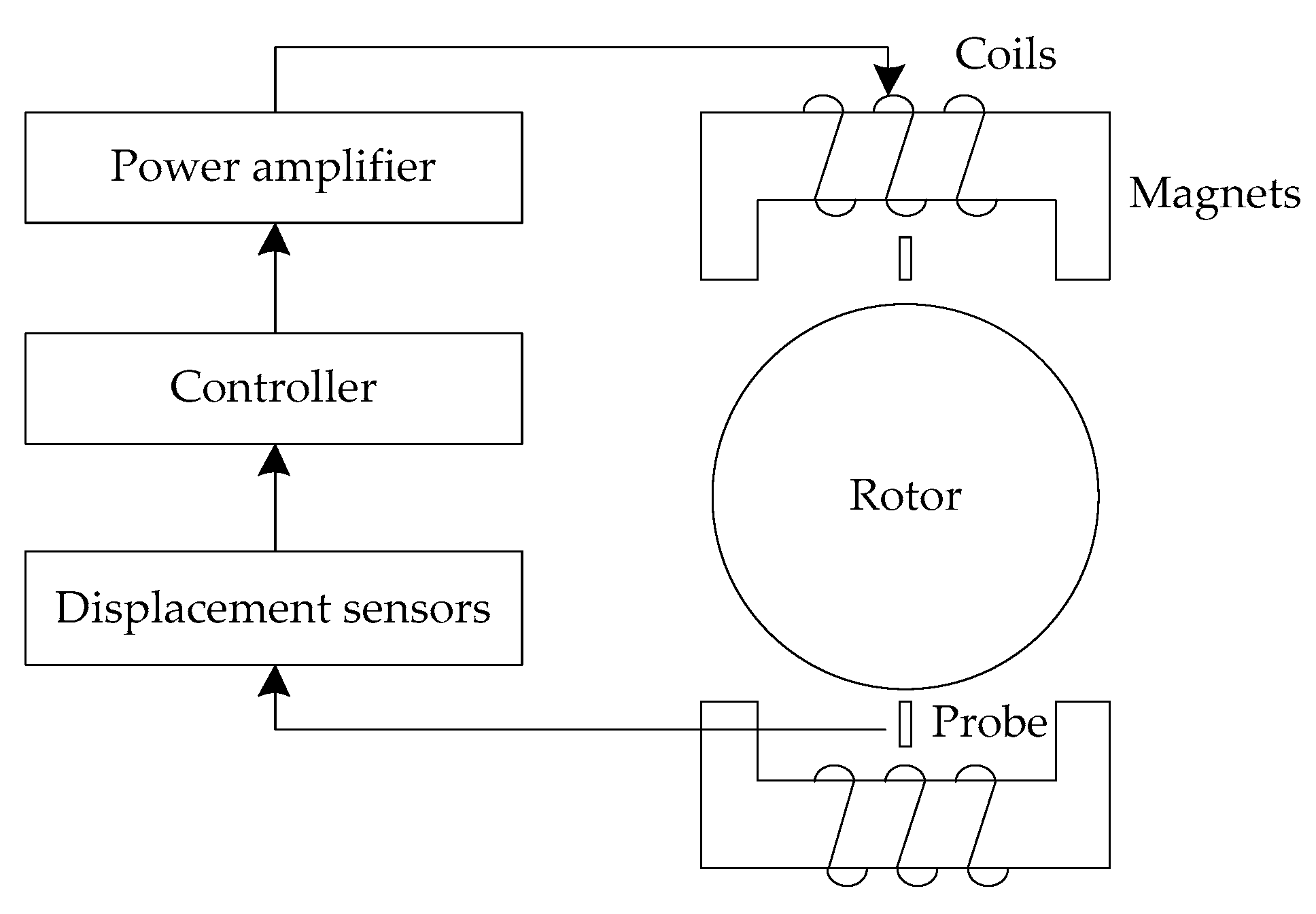
Figure 1 shows the block of the AMB-rotor control system. It contains a controller, power amplifier, electromagnet, rotor, displacement sensor and sensor probe. As the “eye” of the system, the sensor probe can detect the position information of the rotor in real time and transmit it to the controller after being converted by the displacement sensor. The controller provides the control value to the power amplifier based on the difference between the set value of the rotor and the signal measured by the displacement sensor. The power amplifier outputs the current with different amplitudes and directions. The control current is then exerted on each electromagnetic coil to produce corresponding active magnetic forces to suspend the rotor in a given position. The whole process above constitutes the closed-loop control AMB-rotor system.
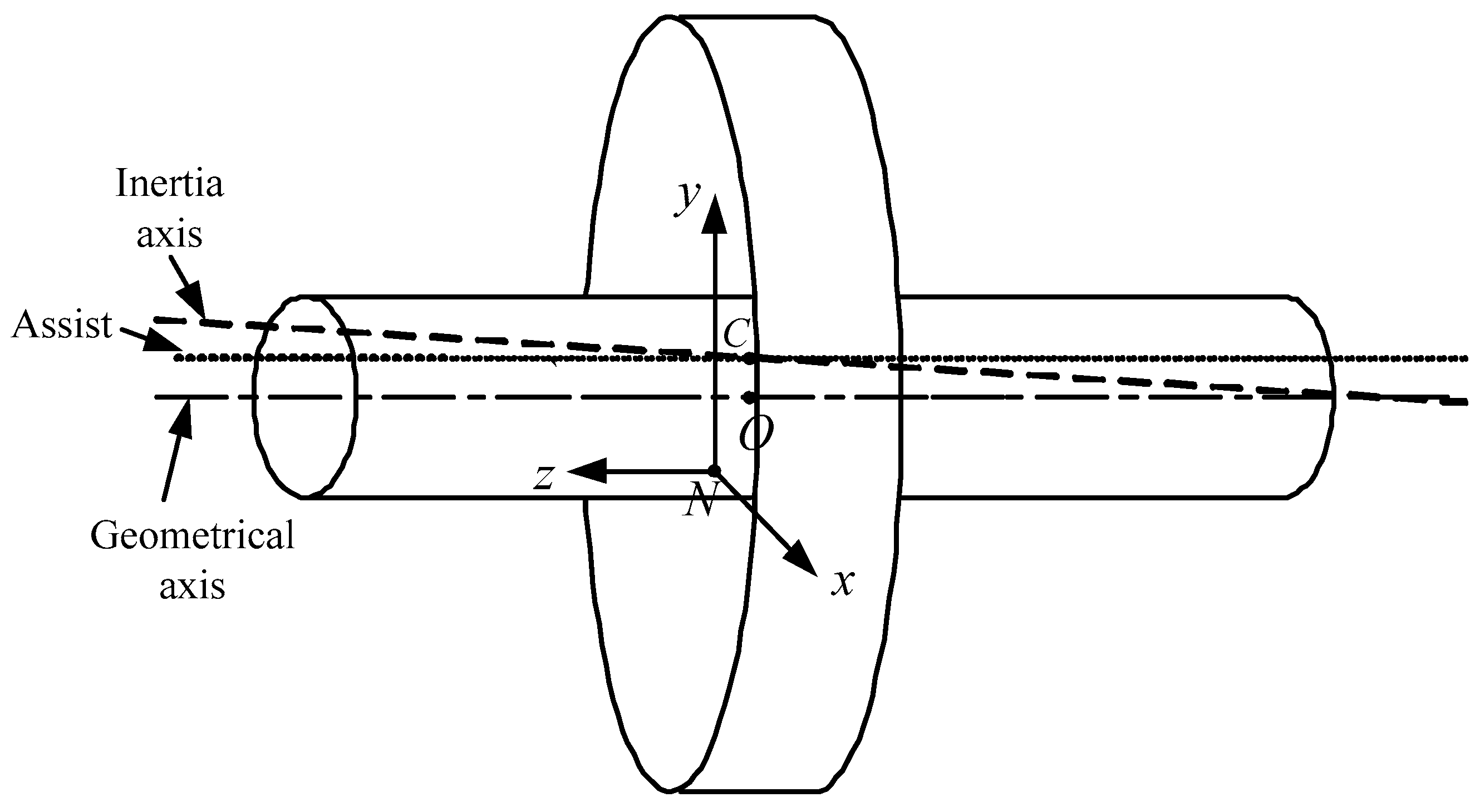
A diagram of the AMB-rotor’s structure is presented in Figure 2. N is the rotor rotation center, C is the center of mass and O is the geometric center. A spatial Cartesian coordinate system Nxyz can be established, where N is the origin and xy is located in a plane parallel to the rotor disc. In addition, the critical speed is designed to be 250 Hz.
2.1. Mechanism Analysis of Unbalanced Vibration
The basic objective of the AMB-rotor control system is to make the displacement sensor detect that the deviation of the geometric axis tends to zero. At this time, the displacement of the rotor is minimal. However, the unbalance of the rotor after dynamic balancing makes the geometric axis deviate from the inertia axis. When the rotor rotates around its geometric axis, its inertia axis also rotates around the geometric axis, which will generate centrifugal force with the synchronous frequency of the rotational speed. Therefore, the AMB-rotor system will generate an equal, corresponding frequency control force to provide a centripetal force, also known as an unbalanced vibration force.
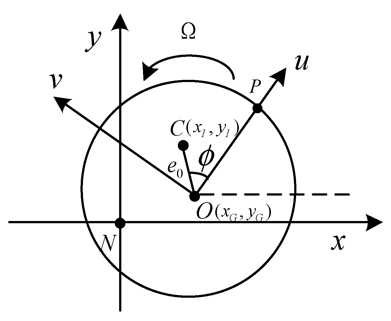
A fixed coordinate system NXY is built with the rotation center N. O in the NXY coordinates can be described as (xG,yG). And C is the center of mass in NXY coordinates, which can be described as (xI,yI). A fixed coordinate system Ouv rotating synchronously with the rotor is established in the central disk of the rotor. P is an absolute position point on the rotor, Ou is in the OP direction, and the initial time is set to be the time when the dotted line is parallel to the axis of NX. In the coordinate system Ouv, e0 is the eccentricity of the vector OC, and ϕ is the angle. As shown in Figure 3, the diagram of the residual unbalance of the AMB-rotor is established.
Firstly, it is proven that while the rotor rotates at the angular velocity Ω, OC also rotates at the angular velocity Ω around point O.
In Figure 3, the rotational center is N, with NXY as the reference coordinate, and the positions of O and C on the rotor are fixed. When the rotor rotates around N at a speed of Ω, both NO and NC rotate around the N point by an angle of Ωt. In order to prove that OC also rotates by the angle Ωt around point O, it is assumed that:
The OC can be expressed as:
When both NO and NC rotate by the angle of Ωt around point N, let
And there are:
By comparing and analyzing the above equations, it can be found that when the rotor rotates around N at the frequency of Ω, the vector OC also rotates around the point O by the angle Ωt.
The residual unbalance of the AMB-rotor is described as:
where δxI and δyI are the disturbance components of the rotor residual unbalance in the X direction and Y direction.
Therefore, we can find that the rotor residual unbalance will cause a disturbance with the synchronous rotation speed.
2.2. Mechanism Analysis of Harmonic Vibration
Because the AMB-rotor system with an open-loop control is unstable, to suspend the AMB-rotor stably at a given position, it is necessary to monitor the position signal as feedback and introduce it into the AMB-rotor system. The particularity of the AMB-rotor and the displacement sensor imposes certain laws on the output radial displacement signal.
If a periodic signal is symmetrical with the original signal relative to the abscissa axis after being translated along the abscissa axis for half a time period, then
Therefore, the periodic signal is an odd harmonic function and the expansion of its Fourier series contains only odd harmonic components.
If a periodic signal is consistent with the original signal after half a period of translation along the abscissa axis, then
Therefore, the periodic signal is an even harmonic function, and its Fourier series expansion only contains even harmonic components.
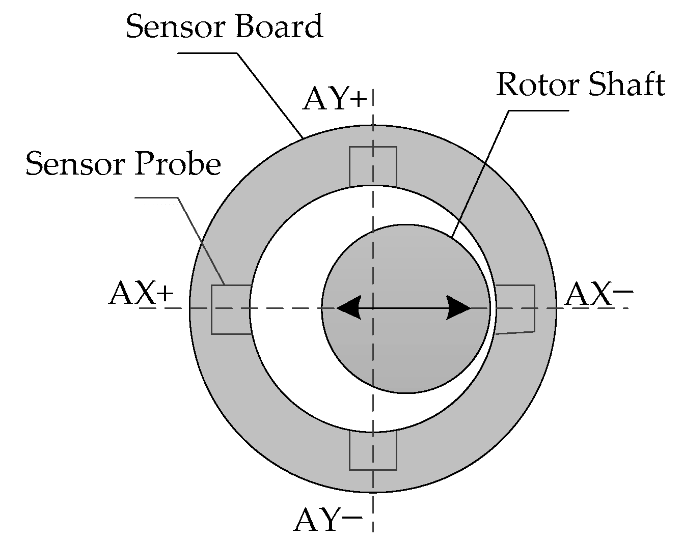
In the AMB-rotor system, the material is uneven, and the surface of the displacement sensor is not round enough. So the output signals of the radial displacement sensor will contain harmonic disturbance, which is called SR. A schematic diagram of rotor shaft displacement detection at the end of a displacement sensor is shown in Figure 4.
If the detection surface of the rotor is smooth, the detection point distance AX+ is probe distance s1 and the distance AX− is probe distance s2. s1 and s2 are independent of the rotational frequency.
If the detection surface of the rotor is rough, the closest distance between the detection surface and the AX+ probe is s1 + Δ1, and the closest distance between the detection surface and the AX− probe is s2 + Δ2. Δ1 and Δ2 are periodic functions with a period of T.
When the linearity of the calibration of two probes is consistent, and the distance of the rotor movement is within the linear range of the two probes, the following relationship can be obtained:
At time t, the output displacement of the sensor in the AX direction can be derived as:
where d0 is a constant. Δ(t) is related to time and is the difference in distance change between two probes.
Combining (13) and (14), it can be concluded that:
According to the definition of odd harmonic function , the signal is symmetric with the original signal about the time coordinate axis after half a period of translation, so Δ(t) is an odd harmonic function. The FFT of the output displacement signal in the AX direction contains only odd harmonic components. Similarly, if the displacement changes in the two probes in the AY, BX and BY directions also have the relationship of an odd harmonic function, the FFT of the output displacement signal only contains odd harmonic components.
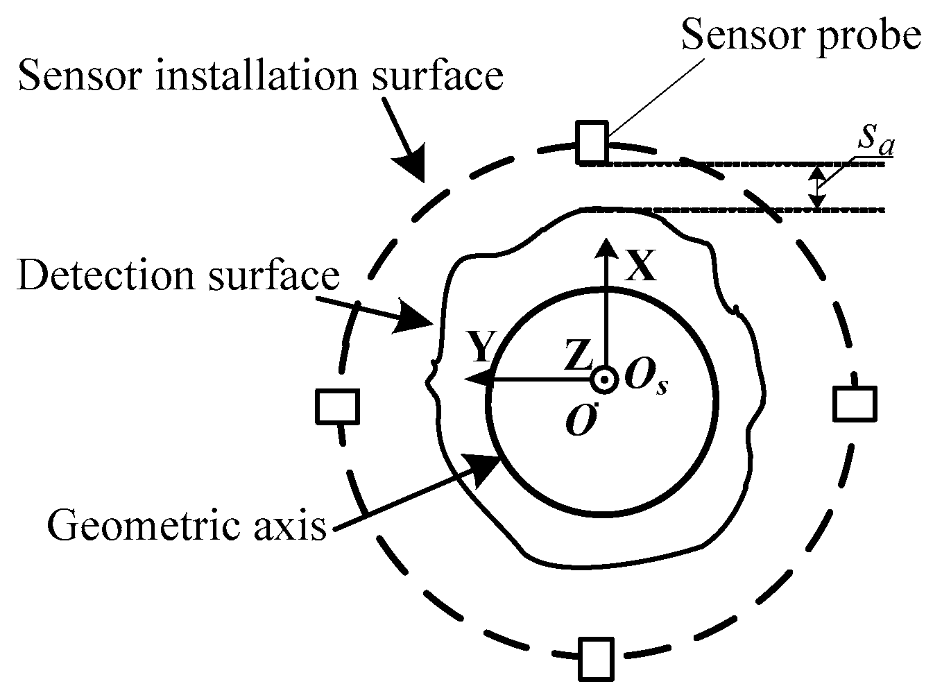
The schematic diagram of SR is illustrated in Figure 5. The outer circle represents the sensor installation surface, the middle circle represents the detection surface of the AMB-rotor shaft, and the inner circle represents the geometric axis. It is assumed that Os is the center of the displacement sensor, and sa is the magnetic gap. The harmonic disturbance component of SR is expressed as:
where hsrax, hsrbx, hsray and hsrby are the harmonic disturbances caused by SR, and k is an odd number and represents the k-th odd harmonic disturbance component. ζai, Aai, ζbi and Abi are the phase and amplitude of the radial displacement sensor signal’s harmonic components, respectively.
So the SR will cause a harmonic disturbance in an odd octave relationship with the rotational speed frequency.
3. Suppression of Harmonic Current with Adaptive Frequency Estimation
3.1. The Structure of Novel Adaptive Notch Filter for Harmonic Sinusoidal Signals
In [22], θ is introduced as a phase shift angle in the state-space equation of the adaptive notch filter (ANF) to make the same frequency suppression effective over the operating speed ranges. The state-space equation of the adaptive filter is
where Ω is the rotational frequency, ε is the convergence parameter, θ is the phase shift angle, and u1(t) and u2(t) are the inputs.
So, an extended structure of the ANF for the harmonic sinusoidal signals can be rewritten as
The structure of the ANF is shown in Figure 6. The structure of subfilter k is illustrated in Figure 7. And there are
where Ω is the rotational frequency, and ε is the positive convergence parameter. The signals and are the inputs which contain harmonic sinusoidal signals and . and are the phase and amplitude of . and are orthogonal, so there are
Laplace transform of (18) can be performed under zero initial conditions, so the relationship between and can be described as:
Similarly, to can be described as:
Substituting into (23) and (24), there are
It indicates that and follow the sinusoidal signals and , respectively.
3.2. Adaptive Frequency Estimation
and are orthogonal signals with the angular velocity . So the can be calculated by
According to (18), the (26) can be obtained as
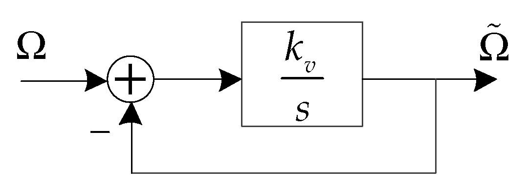
is the estimated value of . An integral loop as shown in Figure 8 can make the final steady-state value of infinitely approximate by .
Therefore, can be expressed as
where kv is a positive coefficient. Since and are a cosine and a sinusoidal signal with the consistent amplitude and phase, respectively, the following equation is satisfied.
where c is a constant. Then (28) can be simplified as
where
The structure of the adaptive frequency estimation (AFE) is illustrated in Figure 9.
3.3. Analysis of Harmonic Current Suppression
The adaptive notch filter for harmonic sinusoidal signals and the adaptive frequency estimation algorithm are used to decrease the harmonic current in the AMB-rotor system. The structure of harmonic current suppression is illustrated in Figure 10. and indicate the harmonic disturbances which contain unbalanced vibration and SR. Gp(s), Gw(s) and Gc(s) are the Laplace transforms of the rotor, power amplifier and controller of the AMB-rotor system, respectively. kad is the sampling factor of A/D converters, and ks is the magnification of the displacement sensor.
Since the structures in AX and AY are completed the same way, AX is analyzed as an example. Let e1 represent the error between u1 and . According to (20), (23) and (25), the relationship between u1 and can be described as
Then
The transfer function from to iax is
Combining (32), (34) can be described as
Therefore, harmonic current can be suppressed at harmonic frequency.
4. Results
4.1. Experimental System
To further verify the correctness of the micro-vibration mechanism analysis and the feasibility of the proposed harmonic current suppression algorithm with adaptive frequency estimation, a simulation using MATLAB and an experiment using an MSCMG whose rotor is levitated by AMBs have been presented. The experimental setup is illustrated in Figure 11. A UPS is used to prevent sudden power outages. A vacuum pump is made to maintain a vacuum degree for rotor operation. The proposed method with frequency estimation is executed in the controller with a TMS320F28335. The sampling frequency of the digital signal processor is 6.67 kHz. The radial channels are decoupled from each other, the structure is symmetrical, and the parameters of these two AMBs are consistent. So, the channels of AX and AY are studied in this paper. The parameters of MSCMG are presented in Table 1. Gp(s), Gw(s) and Gc(s) can be described as
4.2. Simulation Results
The performance of the proposed method is simulated in this section. Firstly, the frequency tracking performance is verified. The initial angular velocity is 100 Hz. Take ε = 3, μ = 0.5 and θ1 = pi/4. The convergence performance of adaptive frequency estimation with two starting points can be seen in Figure 12. The red solid line with an initial frequency of 80 Hz converges to the target frequency 100 Hz in 4.5s. And the blue dotted line with an initial frequency of 140 Hz converges to the target frequency 100 Hz in 19 s. This means that the proposed method can converge from different initial frequencies to the reference frequency. The proposed method has good adaptive tracking performance. But the greater the difference between the target frequency and the initial frequency, the longer the convergence time.
Then, a simulation analysis at 100 Hz is carried out to demonstrate the feasibility of the harmonic current suppression algorithm. The frequency response amplitude of the relationship between and iax with the first to the fifth harmonic current suppression is presented in Figure 13. It illustrates that the amplitude attenuation is 24.5 dB, 47.5 dB, 87.3 dB, 48.3 dB and 40 dB at frequencies of 100 Hz, 200 Hz, 300 Hz, 400 Hz and 500 Hz, respectively. The attenuation of amplitude is sufficient to achieve harmonic current suppression. At the same time, the amplitude at other frequencies remains unchanged.
4.3. Experimental Results
The correctness of the micro-vibration mechanism analysis is first experimentally confirmed. In Figure 14, the amplitude of the rotor displacement in the AX channel and the AY channel is about 25 μm. And the FFT analysis of the AX channel displacement signal in Figure 14c shows that there are only obvious odd harmonic components and no even harmonic components in the displacement signal. The amplitudes of the first to the seventh odd harmonic components in the AX channel displacement signal are −26.3 dB, −34 dB, −44.2 dB and −60.1 dB, respectively.
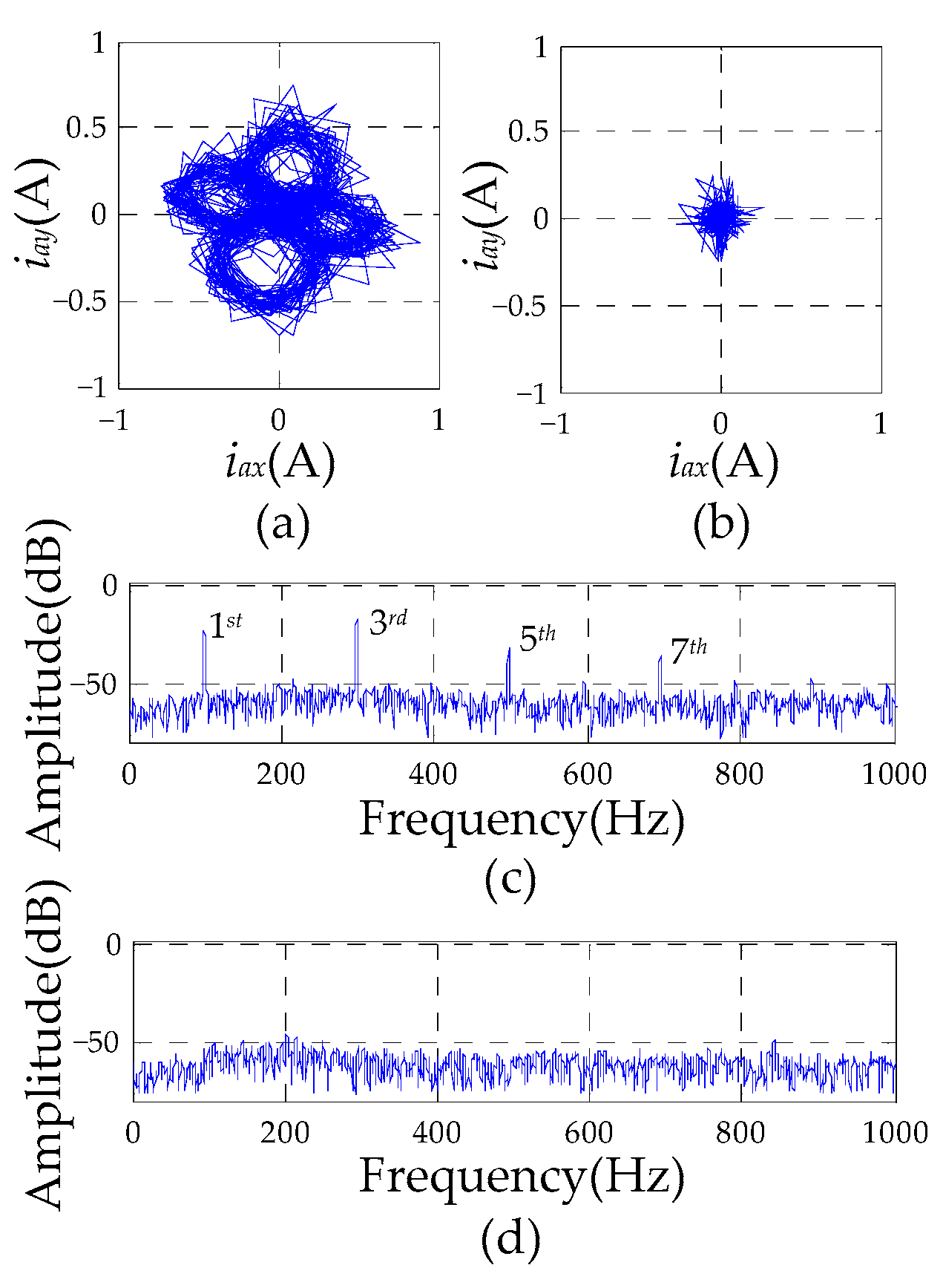
In Figure 15 and Figure 16, the experimental results of the control current in the AX channel and the AY channel before and after implementing the proposed method are illustrated. Due to the presence of only odd harmonic components, the proposed method with the first to the seventh odd harmonic components is considered. The rotating frequency is 50 Hz and the parameters are set to θ1 = 5pi/4, θ3,5,7 = pi/4 in Figure 15. From Figure 15a,c, it can be found that the original control currents in the A-end are about 0.4A, and the first to the seventh odd harmonic components in the A-end control current are −27.1 dB, −24.8 dB, −35.1 dB and −35.2 dB. However, the control current with the proposed method is about 0.15A, which is 37.5% of the primitive amplitude, and the first to the seventh odd harmonic components of the current reduce to −54.9 dB, −51.3 dB, −55 dB and −55.2 dB, which are submerged in noises.
The rotating frequency is 100Hz and the parameter is set to θ1, 3,5,7 = pi/4 in Figure 16. From Figure 16a,c, the original control current in the A-end is about 0.6A, and the first to the seventh odd harmonic components in the A-end control current are −22.9 dB, −17.8 dB, −32.3 dB and −36.7 dB. Compared with the original control currents, the control currents with the proposed method are reduced to 0.18A, which is 30% of the primitive amplitude, and the first to the seventh odd harmonic components of the current are decreased to −53 dB, −53.2 dB, −57.6 dB and −57.3 dB, which are also drowned in noises. We can see that the amplitude of each odd harmonic component has eliminated greater than 90%.
The adaptive characteristics of the proposed harmonic current suppression algorithm are also validated in a run-up experiment. The rotor accelerates from 50 Hz to 250 Hz during the run-up experiment. The FFT analysis of the radial control currents in the AX channel is recorded with a waterfall chart for every 25 Hz in Figure 17. Figure 17a shows the radial control current spectrum without the proposed suppression method. The harmonic components of the radial control current in the AX channel are apparent. However, the first to the seventh odd harmonic components with the harmonic current suppression method in Figure 17b are significantly reduced. It indicates that the proposed method in the AMB-rotor system is feasible over a wide range of rotational speeds.
5. Conclusions
To solve the problem of multi-source disturbances in the closed-loop control AMB-rotor system, this article analyzes the harmonic vibration mechanism of the AMB-rotor system. Then, a harmonic current suppression algorithm with adaptive frequency estimation is proposed. The proposed method can accurately track the rotational frequency, and can also eliminate the harmonic control current in the AMB system while ensuring system stability through angle adjustment. Finally, the correctness of the micro-vibration mechanism analysis and the feasibility of the proposed harmonic current suppression algorithm with frequency estimation are demonstrated through simulation research and experimentation, which are of great significance for further study on micro-vibration control in the AMB-rotor system.
Author Contributions
Conceptualization, Q.C. and J.L.; methodology, Q.C.; software, J.L.; validation, Q.C. and J.L.; formal analysis, Q.C.; investigation, J.L.; resources, J.L.; writing—original draft preparation, Q.C. and J.L.; writing—review and editing, Q.C. and J.L.; visualization, Q.C.; supervision, J.L.; project administration, Q.C.; funding acquisition, Q.C. All authors have read and agreed to the published version of the manuscript.
Funding
The work was supported by in part by the National Natural Science Foundation of China under Grant 62003367.
Data Availability Statement
The data presented in the current study are available on request from the corresponding author.
Conflicts of Interest
The authors declare no conflicts of interest.
References
- Angeletti, F.; Gasbarri, P.; Sabatini, M. Optimal design and robust analysis of a net of active devices for micro-vibration control of an on-orbit large space antenna. Acta Astron. 2019, 164, 241–253. [Google Scholar] [CrossRef]
- Li, L.; Wang, L.; Yuan, L. Micro-vibration suppression methods and key technologies for high-precision space optical instruments. Acta Astron. 2021, 180, 417–428. [Google Scholar]
- Zhou, X.; Sun, J.; Li, H.; Lu, M.; Zeng, F. PMSM open-phase fault-tolerant control strategy based on four-leg inverter. IEEE Trans. Power Electron. 2020, 35, 2799–2808. [Google Scholar]
- Ji, J.C.; Leung, A.Y.T. Resonances of a non-linear s.d.o.f. system with two time-delays in linear feedback control. J. Sound Vib. 2002, 253, 985–1000. [Google Scholar]
- Ji, J.C.; Hansen, C.H. Non-linear oscillations of a rotor in active magnetic bearings. J. Sound Vib. 2001, 240, 599–612. [Google Scholar] [CrossRef]
- Sun, J.; Zhao, J.; Wang, K. Online surge detection method based on axial displacement sensor of MSCC. IEEE Sens. J. 2019, 19, 6029–6036. [Google Scholar] [CrossRef]
- Tang, J.; Peng, Z.; Liu, B. Control of rotor’s vernier-gimballing for a magnetically suspended flywheel. IEEE Trans. Ind. Electron. 2017, 64, 2972–2981. [Google Scholar]
- Huang, L.; Wu, Z.; Wang, K. Indirect measurement of rotor dynamic imbalance for control moment gyroscopes via gimbal disturbance observer. Sensors 2018, 18, 1873. [Google Scholar] [CrossRef]
- Serdar, H.; Ozcelik, Z. Design of laboratory dynamic balancing device and investigation of vibrations of rotating bodies. Eng. Technol. Appl. Sci. Res. 2021, 6, 9–21. [Google Scholar]
- Li, J.; Liu, G.; Zheng, S.; Cui, P. Micro-jitter control of magnetically suspended control moment gyro using adaptive LMS algorithm. IEEE/ASME Trans. Mech. 2022, 27, 327–335. [Google Scholar] [CrossRef]
- Zheng, S.; Chen, Q.; Ren, H. Active balancing control of AMB-rotor systems using a phase-shift notch filter connected in parallel mode. IEEE Trans. Ind. Electron. 2016, 63, 3777–3785. [Google Scholar]
- Jiang, K.; Zhu, C.; Tang, M. A uniform control method for imbalance compensation and automation balancing in active magnetic bearing-rotor systems. J. Dyn. Sys. Meas. Con. 2012, 134, 021006–021019. [Google Scholar]
- Li, J.; Liu, G.; Cui, P. Suppression of harmonic vibration in AMB-Rotor systems using double-input adaptive frequency estimator. IEEE Trans. Ind. Electron. 2021, 69, 2986–2995. [Google Scholar] [CrossRef]
- Kim, C.; Lee, C. In situ runout identification in active magnetic bearing system by extended influence coefficient method. IEEE/ASME Trans. Mech. 1997, 2, 51–57. [Google Scholar]
- Setiawan, J.D.; Mukherjee, R.; Maslen, E.H. Adaptive compensation of sensor runout for magnetic bearings with uncertain parameters: Theory and experiments. J. Dyn. Sys. Meas. Con. 2001, 123, 211–218. [Google Scholar] [CrossRef]
- Cai, K.; Deng, Z.; Peng, C. Suppression of harmonic vibration in magnetically suspended centrifugal compressor using zero-phase odd-harmonic repetitive controller. IEEE Trans. Ind. Electron. 2020, 67, 7789–7797. [Google Scholar] [CrossRef]
- Cui, P.; Li, W.; Zhou, X. Multi-order repetitive controller for harmonic current suppression in magnetically suspended rotor system. J. Vib. Con. 2020, 27, 2657–2668. [Google Scholar]
- Li, J.; Liu, G.; Cui, P.; Zheng, S. An improved resonant controller for AMB-rotor system subject to displacement harmonic disturbance. IEEE Trans. Power Electron. 2022, 37, 5235–5244. [Google Scholar] [CrossRef]
- Zhou, K.; Lu, W.; Yang, Y. Harmonic control: A natural way to bridge resonant control and repetitive control. In Proceedings of the American Control Conference, Washington, DC, USA, 17–19 June 2013; pp. 3189–3193. [Google Scholar]
- Peng, C.; Zhou, Q. Direct vibration force suppression for magnetically suspended motor based on synchronous rotating frame transformation. IEEE Access 2019, 7, 37639–37649. [Google Scholar]
- Cui, P.; Du, L.; Zhou, X. Harmonic vibration control of MSCMG based on multi-synchronous rotating frame transformation. IEEE Trans. Ind. Electron. 2022, 69, 1717–1727. [Google Scholar] [CrossRef]
- Liu, G.; Li, J.; Zheng, S.; Chen, Q.; Liu, H. Suppression of synchronous current using double input improved adaptive notch filter algorithm. IEEE Trans. Ind. Electron. 2020, 67, 8599–8607. [Google Scholar] [CrossRef]
Figure 1.
The block of the AMB-rotor control system.

Figure 2.
The diagram of the AMB-rotor structure.

Figure 3.
The diagram of the AMB-rotor residual unbalance.

Figure 4.
Schematic diagram of rotor shaft displacement detection.

Figure 5.
Schematic diagram of SR.

Figure 6.
The structure of the ANF for harmonic sinusoidal signals.

Figure 7.
The structure of k-th subfilter.

Figure 8.
An integral loop from Ω to .

Figure 9.
The structure of the adaptive frequency estimation.

Figure 10.
The structure of harmonic current suppression.

Figure 11.
The experimental setup of MSCMG.

Figure 12.
Simulated convergence performance of adaptive frequency estimation with different starting points.
Figure 12.
Simulated convergence performance of adaptive frequency estimation with different starting points.

Figure 13.
Frequency response amplitude of the relationship between and iax with the first to the fifth harmonic current suppression.
Figure 13.
Frequency response amplitude of the relationship between and iax with the first to the fifth harmonic current suppression.

Figure 14.
Experimental results of rotor displacement: (a) displacement signal in AX channel; (b) displacement signal in AY channel; (c) FFT analysis of displacement signal in AX channel.
Figure 14.
Experimental results of rotor displacement: (a) displacement signal in AX channel; (b) displacement signal in AY channel; (c) FFT analysis of displacement signal in AX channel.

Figure 15.
Comparison of current results in A-end at 50 Hz: (a) A-end control current without proposed algorithm; (b) A-end radial control current with proposed algorithm; (c) radial control current spectrum in AX channel with (a); (d) radial control current spectrum in AX channel with (b).
Figure 15.
Comparison of current results in A-end at 50 Hz: (a) A-end control current without proposed algorithm; (b) A-end radial control current with proposed algorithm; (c) radial control current spectrum in AX channel with (a); (d) radial control current spectrum in AX channel with (b).

Figure 16.
Comparison of current results in A-end at 100Hz: (a) A-end control current without proposed algorithm; (b) A-end radial control current with proposed algorithm; (c) radial control current spectrum in AX channel with (a); (d) radial control current spectrum in AX channel with (b).
Figure 16.
Comparison of current results in A-end at 100Hz: (a) A-end control current without proposed algorithm; (b) A-end radial control current with proposed algorithm; (c) radial control current spectrum in AX channel with (a); (d) radial control current spectrum in AX channel with (b).

Figure 17.
Spectrum of control current in experiments: (a) AX channel without the proposed harmonic current suppression algorithm; (b) AX channel with the proposed harmonic current suppression algorithm.
Figure 17.
Spectrum of control current in experiments: (a) AX channel without the proposed harmonic current suppression algorithm; (b) AX channel with the proposed harmonic current suppression algorithm.


Table 1.
The parameters of MSCMG.
| Parameter | Value | Parameter | Value |
|---|---|---|---|
| m | 16.7 kg | kP | 4.7 |
| ki | 600 N·A−1 | kI | 2.5 |
| kx | 2.4 × 10⁶ N·m−1 | kD | 0.001725 |
| R | 2.3 Ω | Tf | 0.000225 |
| L | 20 mH | kad | 1365 |
| kamp | 0.8 | ks | 8333 |
| kico | 6.4 | kc | 0.495 |
Disclaimer/Publisher’s Note: The statements, opinions and data contained in all publications are solely those of the individual author(s) and contributor(s) and not of MDPI and/or the editor(s). MDPI and/or the editor(s) disclaim responsibility for any injury to people or property resulting from any ideas, methods, instructions or products referred to in the content. |
© 2024 by the authors. Licensee MDPI, Basel, Switzerland. This article is an open access article distributed under the terms and conditions of the Creative Commons Attribution (CC BY) license (https://creativecommons.org/licenses/by/4.0/).
Share and Cite
MDPI and ACS Style
Chen, Q.; Li, J. Study on the Mechanism and Suppression of Harmonic Vibration of AMB-Rotor System. Vibration 2024, 7, 83-97. https://doi.org/10.3390/vibration7010005
AMA Style
Chen Q, Li J. Study on the Mechanism and Suppression of Harmonic Vibration of AMB-Rotor System. Vibration. 2024; 7(1):83-97. https://doi.org/10.3390/vibration7010005
Chicago/Turabian StyleChen, Qi, and Jinlei Li. 2024. "Study on the Mechanism and Suppression of Harmonic Vibration of AMB-Rotor System" Vibration 7, no. 1: 83-97. https://doi.org/10.3390/vibration7010005