Article

Development of Type A Quadrupole Magnet for Siam Photon Source II

Synchrotron Light Research Institute, Muang, Nakhon Ratchasima 30000, Thailand
*
Author to whom correspondence should be addressed.
Particles 2023, 6(2), 664-673; https://doi.org/10.3390/particles6020039
Submission received: 29 April 2023 / Revised: 31 May 2023 / Accepted: 7 June 2023 / Published: 9 June 2023
(This article belongs to the Special Issue Generation and Application of High-Power Radiation Sources)

Abstract

:
A prototype of a type A quadrupole magnet has been designed and manufactured for the 3 GeV storage ring of Siam Photon Source II, the second synchrotron light source in Thailand. The required quadrupole gradient is 51 T/m with the magnet effective length being 162 mm. Magnet modeling and magnetic field calculation were performed using Radia and Opera-3D. The bore radius of the magnet is 16 mm. The magnet will be operated at the excitation of 5544 A-turns. A mechanical analysis of the magnet structure was performed in SOLIDWORKS and ANSYS, where the maximum deformation of 0.003 mm was found at the magnet poles, and the first-mode natural frequency was higher than 100 Hz. The magnet yoke is made of AISI 1006 low-carbon steel with a fabrication tolerance of ±0.020 mm. Magnet coils are water-cooled and made of high-purity copper. The temperature rise of the coils was below 3.0 °C at the maximum excitation of 6664 A-turns, which is 20% above the operating point. Magnetic field measurement was carried out using the Hall probe technique. The measured magnetic field and coil temperature of the prototype show good agreement with the calculations.

1. Introduction

Siam Photon Source II (SPS-II), upon its completion, will be the second synchrotron light source in Thailand with a beam energy of 3.0 GeV and a beam current of 300 mA. The SPS-II storage ring consists of 14 Double Triple Bend Achromat (DTBA) cells with a total ring circumference of 327.5 m. Following the successful fourth generation synchrotron light sources that adopted a Multi-Bend Achromat (MBA) lattice [1,2,3], the DTBA lattice allows an ultralow emittance. The beam emittance of the SPS-II storage ring is below 1 nm-rad, more than 40 times lower than the existing Siam Photon Source storage ring [4]. This will provide better photon beam characteristics and enable various experimental techniques and applications [5]. The DTBA lattice contains a series of dipole, combined dipole–quadrupole, quadrupole, sextupole, and octupole magnets for controlling electron beam characteristics. With an additional straight section in the middle of the DTBA cell, space usage can be enhanced, and more insertion devices can be installed. Detailed information regarding the lattice design is reported elsewhere [6].
In the DTBA lattice of the SPS-II storage ring, seven families of quadrupole magnets are used to focus and defocus the electron beam. These include focusing quadrupoles QF1, QF4, QF6, and QF8 and defocusing quadrupoles QD2, QD3, and QD5. The required gradient of magnetic field of these quadrupole magnets ranges from 44 T/m to 60 T/m, in order to have the focusing effect needed for a small emittance. These values are moderate compared to magnet requirements of other upgrade projects and new machines where the quadrupole gradient can be as high as 105 T/m [7]. Quadrupole magnets for the SPS-II storage ring with a high field gradient are in the region where the Beam Stay Clear (BSC) is small (7.2 mm to 12.4 mm) [8], and a high gradient can be obtained from a small magnet aperture. On the other hand, quadrupole magnets with lower field gradients are in the region that requires larger BSC (19.1 mm), and the small magnet aperture is inappropriate. It is also difficult to achieve good field quality within a large Good Field Region (GFR) in a small-aperture magnet since the relative multipole errors vary with the (n − 2)th power of the ratio between GFR radius and magnet aperture [9]. Consequently, quadrupole magnets for the SPS-II storage ring are divided into two types: type A with a small magnet aperture (QF1, QD2, QD3, QD5, QF6, and QF8) and type B with a large magnet aperture (QF4).
In the design and construction of SPS-II, other aims are to improve Thai researchers’ skills and knowledge of advanced accelerator technologies and to enhance the manufacturing capability of Thai industries. Prototypes of various machine components, such as magnets, vacuum chambers, and girders, have been developed. In this work, we report the design, magnetic field calculation, and magnetic field measurement of a prototype of a type A quadrupole magnet, QD2, with a bore radius of 16 mm. Mechanical analysis of the magnet structure, manufacturing techniques, and temperature measurement of the magnet coils are also discussed.

2. Magnet Design

2.1. Requirements and Design Parameters

Requirements and specifications of the prototype of the type A quadrupole magnet for the SPS-II storage ring are summarized in Table 1. At the position of the defocusing quadrupole QD2 magnet in the DTBA cells, the required maximum focusing strength (k) is −5.1 m−2, with the negative sign representing a horizontal defocusing effect. Quadrupole magnets focus the electron beam in one plane (horizontal or vertical) and defocus it in the other plane. The corresponding quadrupole field gradient (G) is 51 T/m, which is calculated using [10]:
k m 2 = 0.2998 G T / m β E GeV .
The parameter β = v/c ≈ 1 represents the relative electron velocity, and the electron energy € is 3.0 GeV. The quadrupole gradient of 51 T/m can be obtained from a quadrupole magnet with a bore radius of 16 mm operated at the excitation of 5544 A-turns. The required effective length in the lattice design is 162 mm. The length of the fringe field at each end of the quadrupole magnet is approximately half of the bore radius [11]. Therefore, the magnet’s physical length or the length of the magnet yoke can be shorter than the effective length. The value of the physical length found in this work is 144 mm. The required GFR, where the gradient error and/or the multipole errors are less than 5 × 10⁻⁴, is ±10 mm. This is to cover the calculated horizontal BSC of 8.3 mm at the position of QD2 in the DTBA cells. The magnet yoke is made of AISI 1006 low-carbon steel with a fabrication tolerance of ±0.020 mm. The magnet coils are water-cooled with a temperature rise below 3.0 °C at the maximum current (20% above the operating point).
The 20% margin, which is calculated directly from the operating current, is also used for pole shape optimization of all quadrupole magnets for the SPS-II storage ring. The calculated quadrupole strength variation when insertion devices are installed ranges from −9.1% to +12.6% of the nominal strength of QD2, QD3, QD5, QF1, and QF4 magnets. The 20% margin is expected to be sufficient for the quadrupole field adjustment during the first machine commissioning and after installation of insertion devices. Nonetheless, it should be noted that the saturation effect is disregarded, and the quadrupole gradient of the magnets may not be variable up to 20% above the designed value. For QD2, the largest quadrupole strength variation is −9.1% while the calculated quadrupole gradients at −20% and +20% of the operating current are −18.1% and +11.5%, respectively. More details about magnetic field calculation will be described in the following sections.

2.2. Magnetic Field Calculation

Magnet modeling and magnetic field calculation of type A quadrupole magnets are mainly carried out using Opera-3D [12], finite element analysis software for magnetic field simulation, as illustrated in Figure 1a. The magnet yoke is shown in green, and the coils are shown in red. The B–H curve of AISI 1006 low-carbon steel is used for nonlinear material properties of the magnet yoke with isotropic properties assumption. The turn number of the magnet coils is 56. Each coil is electrically connected in a series, so the four coils carry the same electric current. The calculated operating current of the magnet is 99 A for the quadrupole gradient of 51 T/m. Reflection symmetry is applied to the model with a tangential magnetic field on the x–y plane and a normal magnetic field on the x–z plane and y–z plane. The pole profile of the type A quadrupole magnet follows the hyperbolic shape:
2 xy   = ± R 2 ,
with the bore radius (R) of 16 mm [10,11]. The poles are shimmed near the edges to improve magnetic field uniformity along x at y = z = 0 to be better than 5 × 10⁻⁴ within the GFR of ±10 mm. Magnet design and pole shape optimization are originally performed using Radia simulation software based on a finite volume integral approach [13,14]. The same B–H curve of AISI 1006 low-carbon steel is used in Radia and Opera-3D simulations. We have determined that pole shape optimization and shimming is effective at the operating point with extra margins of ±20%. Pole end chamfer is applied after magnetic field measurement to improve the integrated field quality, if necessary. Figure 1b shows the magnetic field contour on the x–y plane of the type A quadrupole magnet at z = 0 and an operating current of 99 A. Magnet coils are not seen on the field contour plot since the relative permeability of copper is close to 1. A maximum magnetic field of 1.8 T is found near the pole tip, which is just below the magnetic saturation of 2.0 T for low-carbon steel [15].

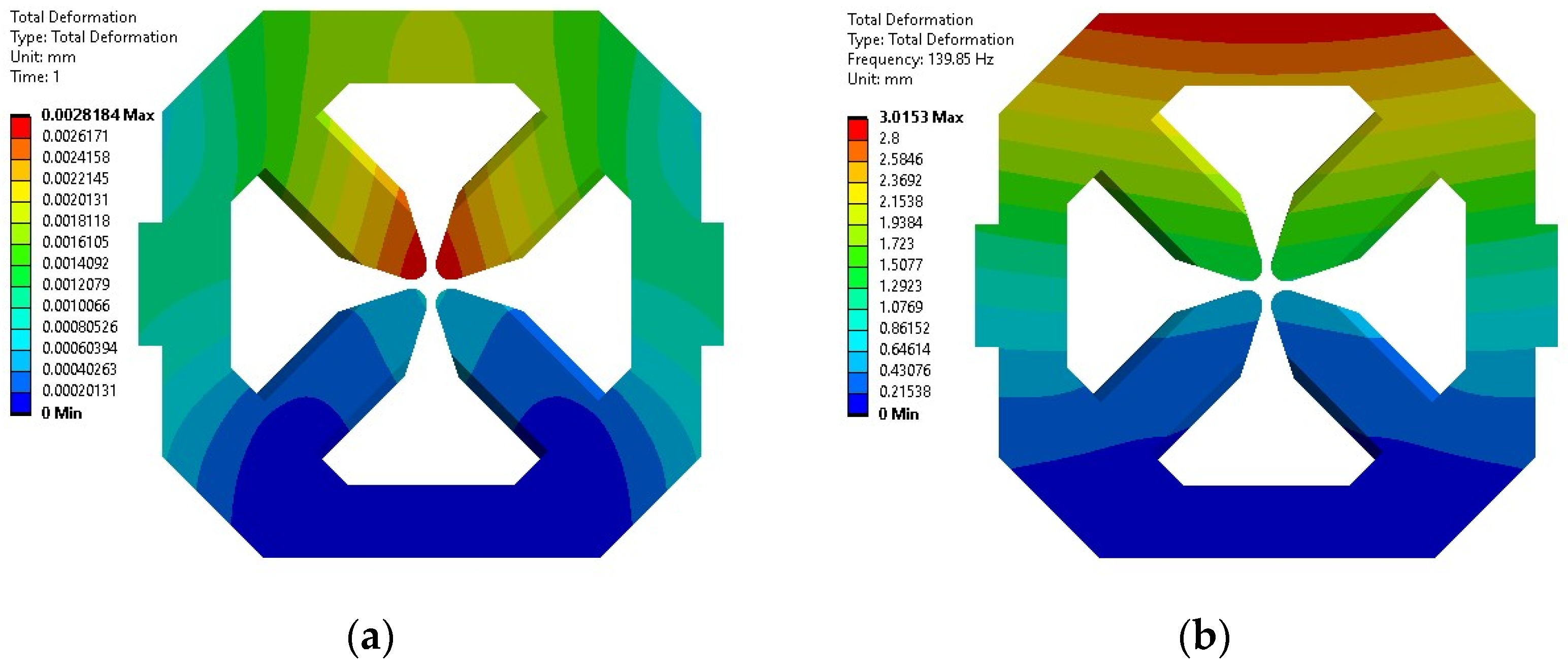
2.3. Mechanical Analysis

Mechanical analysis of the magnet structure of type A quadrupole magnets is performed in SOLIDWORKS [16] and ANSYS [17]. A coil weight of 20 kg and a magnetic force of 3200 N for each magnet pole are included in the simulation, in addition to the weight of the magnet yoke itself. The fixed geometry or fixture of the model is at the bottom surface of the magnet. The maximum static deformation of the magnet structure is 0.003 mm at the upper magnet poles, as seen in Figure 2a. Simulation without the magnetic force produces a maximum static deformation of 0.002 mm (not shown here); hence, the magnet deformation is mainly due to the weight of magnet coils and yoke. Fabrication and assembly tolerance of the magnet is ±0.020 mm; therefore, the deformation is considered small and is in the acceptable range. The first-mode natural frequency of the magnet is 140 Hz, which is found from a modal analysis in ANSYS. When the magnet is used in the SPS-II storage ring, it is installed and aligned with other magnets on a girder. Modal analysis of the magnets–girder assembly and vibration measurement needs to be carried out to investigate the vibration effects on the magnets and girder system, yet it is beyond the scope of this work. Total deformation from the modal analysis of the quadrupole magnet alone is presented in Figure 2b.

2.4. Hydraulic Calculation

Temperature rise of the magnet coils is calculated using a set of equations adapted from Tanabe’s method where the pressure drops through the water circuit, and the Reynolds number and the friction factor for turbulent flow are considered [11]. Good heat transfer through the thin fluid film between the conductor’s inner surface and the bulk fluid flow is also assumed. The coils of the type A quadrupole magnet are water-cooled and made of OF-OK® oxygen-free high-purity copper with the dimensions of 7.5 × 7.5 mm and a 4 mm hole for water cooling. The water flow is calculated at the maximum pressure drop of 5 bar, which results in a total flow rate of 5.0 L/min and a flow velocity of 1.6 m/s. One cooling circuit is used for each coil; therefore, there are four parallel cooling circuits in total. The coil cooling is designed for a maximum current of 119 A, which is 20% above the operating current. The calculated temperature rise of the coils is 2.0 °C at the operating current of 99 A and 2.8 °C at the maximum current of 119 A.
For a low-emittance storage ring, vibration of all machine components is of concern [18]. A flow velocity of 1.6 m/s can be considered high, and the flow of water in the cooling circuits can be a source of vibration. In the operation of a type A quadrupole magnet, the flow velocity of cooling water can be reduced to 1.0 m/s by reducing the flow rate to 3.0 L/min. The resulting temperature rise of the magnet coils becomes 4.7 °C, which is still in our acceptable range of 5.0 °C for low thermal effect on electron beam stability. Nevertheless, the effects of vibration will need to be studied.

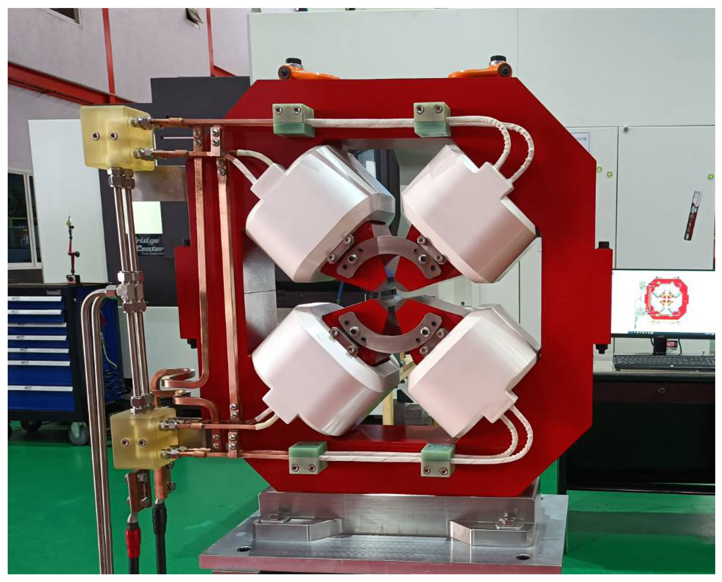
3. Magnet Manufacturing

3.1. Magnet Yoke

The yoke of a type A quadrupole magnet is made of AISI 1006 low-carbon steel with a carbon content less than 0.08%. Chemical components of a material, magnetic properties (B–H data), and some physical properties such as density, yield strength, elastic modulus, and Poisson’s ratio are measured by the manufacturer and/or the supplier of the material. Determination of defects within the raw material is also carried out using ultrasonic testing at the magnet manufacturing facility. The magnet yoke is fabricated using a Wire Cut Electrical Discharge Machining (EDM) technique with a fabrication and assembly tolerance of ±0.020 mm at the magnet pole. Fabrication tolerance at the other parts of the magnet is more relaxed. Mechanical design and magnet yoke fabrication of type A quadrupole magnets adopt the techniques used in the construction of a sextupole magnet prototype as reported in [19]. The magnet yoke is divided into the upper and lower halves for assembly of magnet coils and installation of a vacuum chamber in the storage ring. Each half-yoke has one removable magnet pole for magnet coil insertion. The removable pole is precisely fixed in position using pins and a pole clamp. All mating surfaces for magnet yoke assembly are prepared using a grinding technique. Dimensional tolerance of the magnet yoke is investigated using a Coordinate Measuring Machine (CMM), and according to the CMM results the tolerance of magnet yoke fabrication and assembly meets our requirements.

3.2. Magnet Coils

Before the coil winding, a hollow copper conductor is insulated using NOMEX® Meta-aramid tape with 50% insulation overlap. The coils are wound using a semi-automatic coil winding machine and impregnated in epoxy using a Vacuum Pressure Impregnation (VPI) technique. The coil winding machine and VPI system are newly designed and developed for coil manufacturing of SPS-II magnets. The epoxy system for the coil impregnation is a mixture of Araldite F (base resin), DT040 (flexibilizer), HY905 (hardener), and DY073 (accelerator). A potting mold is used during the VPI process to control the coil dimension. Space between magnets within the DTBA lattice of the SPS-II storage ring is quite tight; therefore, it is crucial to have the coil dimension exactly match the design. The coils are then assembled with the magnet yoke as well as the electrical and hydraulic connectors as shown in Figure 3.

4. Results and Discussion

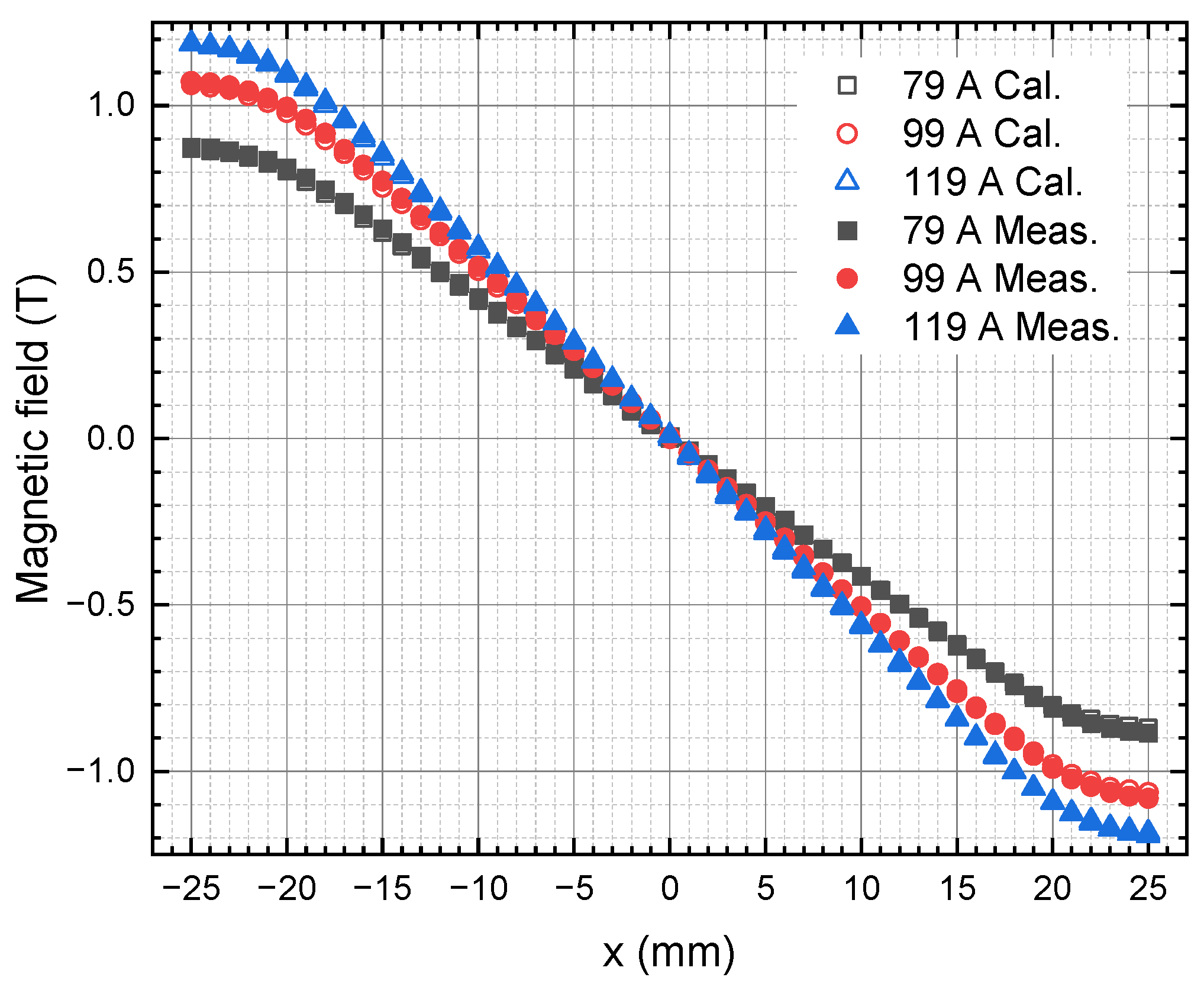
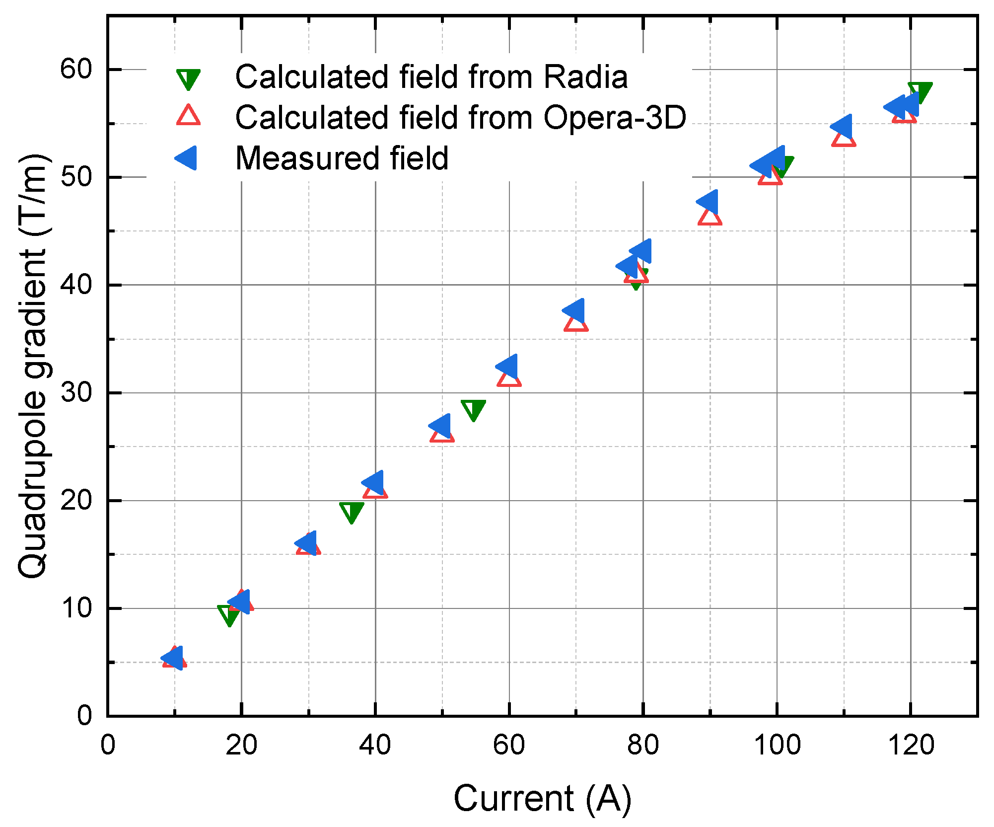
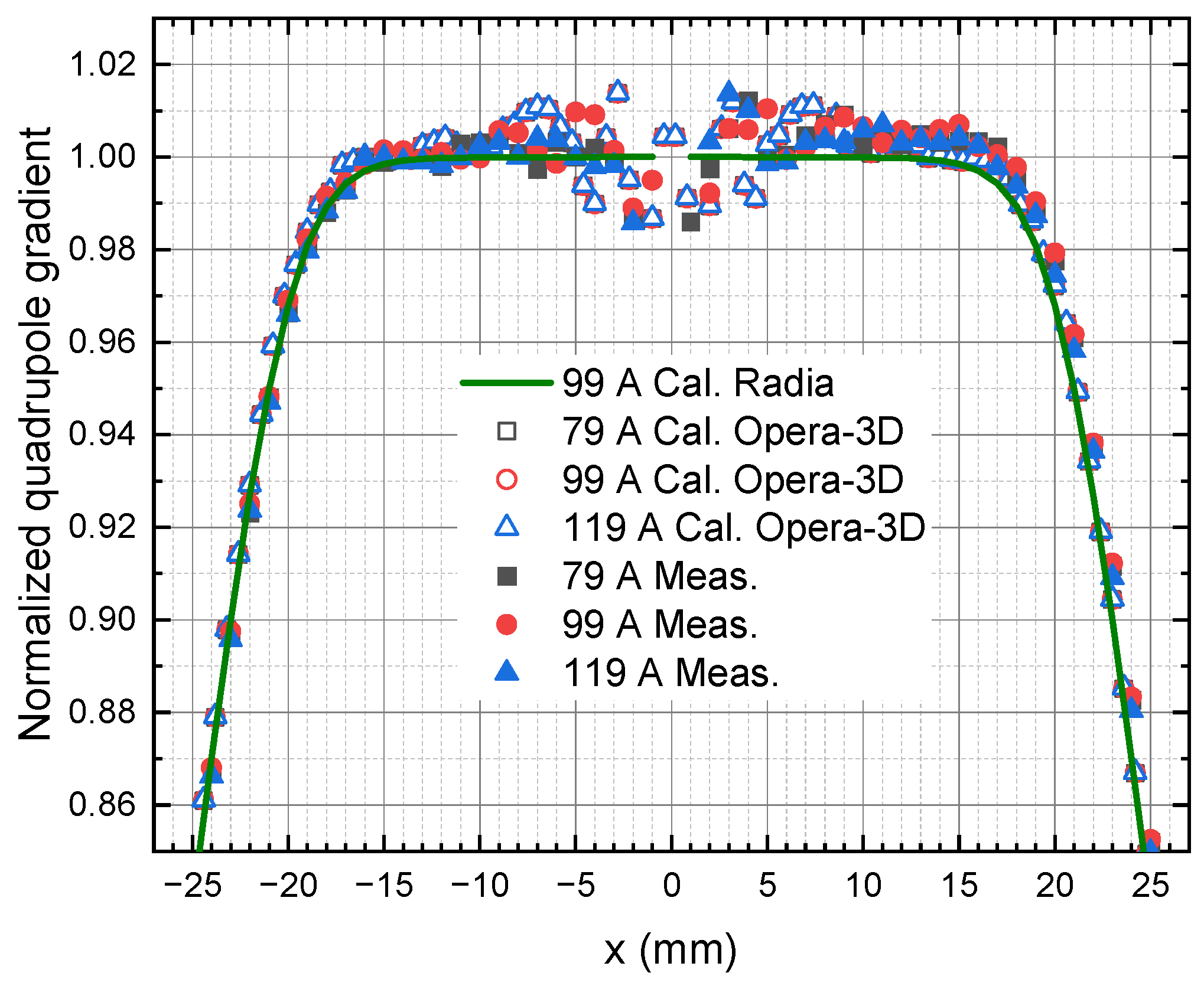
4.1. Magnetic Field Measurement

The magnetic field measurement of the type A quadrupole magnet is performed using the Hall probe technique. The probe is a Lake Shore 3-axis probe used with the Model 460 Gaussmeter [20]. Measurement accuracy is 0.25% of the reading value up to 2 T at 25 °C. Figure 4 shows the vertical magnetic field (By) of the quadrupole magnet along the x-coordinate (y = z = 0) at the operating current of 99 A and with ±20% margins. The magnetic field gradient or quadrupole gradient of the magnet can be obtained from the slope of the plot in Figure 4, or more accurately, by fitting the plot to multipole field expansion:
B y x =   B 0 + B 1 x + 1 2 B 2 x 2 + 1 6 B 3 x 3 +   ,
where the coefficients B0, B1, B2, and B3 are dipole field, quadrupole gradient, sextupole gradient, and octupole gradient, respectively. The quadrupole gradient as a function of applied current (excitation curve) of the type A quadrupole magnet is plotted in Figure 5 for both calculated and measured magnetic fields. At the operating point, where the quadrupole gradient is 51 T/m, the magnetic field is very close to saturation. The saturation most likely occurs near the pole tip where the magnetic field is highest, as seen in Figure 1b. In general, this effect may be reduced by decreasing the bore radius of the magnet, but in our case, the minimum bore radius is limited by the BSC and the vacuum system’s requirement that the cross-section of the vacuum chamber is kept constant along the storage ring. As a result, the bore radius of the type A quadrupole magnet cannot be smaller.
The calculated magnet efficiencies are 97%, 95%, and 89% at the applied currents of 79 A, 99 A, and 119 A, respectively. The magnet efficiency (η) is calculated using:
η × 2 μ 0 NI = B 1 R 2   ,
where µ0 is the magnetic permeability in vacuum, N is the turn number, and I is the excitation current. It is a ratio between the excitation current required to excite the desired field in the magnet aperture and the total current in the circuit, which includes the current required to drive the magnetic flux through the yoke [11]. This parameter also shows how close the operating point is to the linear regime of the excitation curve.
For a typical well-designed magnet, the magnet should be operated in the linear regime of the excitation curve, and the magnet efficiency should be at least 98%. In our case, it is inevitable that the quadrupole magnet is to be operated near saturation due to the BSC and vacuum chamber limitations, as well as the tight spaces between magnets in the storage ring. Because the pole shape is optimized at the operating point with the extra margins of ±20% for a good field quality, nonlinearity effects will not be a problem as long as the magnet is operated in the optimization range. However, power consumption of the magnet will be slightly high because of the low efficiency. This scenario is similar to the high-gradient quadrupole magnets for ESRF-EBS [21].
Figure 6 shows the normalized quadrupole gradient derived from Figure 4 along the x-coordinate (y = z = 0) at the operating current of 99 A and with ±20% margins. Results of calculation and measurement show good agreement, although the data from measurement and calculation using Opera-3D are scattered (in an order of 10−2) due to the accuracy of the Hall probe and the meshing limitation in the finite element analysis. The calculated result from Radia, which is used in pole shape optimization, is plotted for the applied current of 99 A as a reference. The normalized gradient error obtained from Radia is below 5 × 10⁻⁴ within the GFR of ±10 mm. Usually, multipole errors or field harmonics of multipole magnets can be accurately measured using a rotating coil or a stretched wire technique [22,23,24]. The measuring coils are rotated in the magnet aperture, and an induced voltage from the change in magnetic flux through the coils is measured. In this work, magnetic field measurement is only performed using the Hall probe technique or field mapping technique. The multipole fields are analyzed based on multipole field expansion as expressed in Equation (3) instead. The multipole coefficients Bn of the type A quadrupole magnet obtained from the so-called fitting method [25] are summarized in Table 2 for the applied current of 99 A.
In the Radia simulation, meshing is not needed for the air region, and magnetic field strength can be calculated anywhere in space including the region inside the magnet aperture. The magnetic field (not shown here) and normalized quadrupole gradient data calculated using the Radia simulation are less dispersed. As a result, multipole fields extracted from Radia results using the fitting method are more accurate. The dipole term is negligible in the calculations (both Radia and Opera-3D) as magnet symmetry is used in the modeling. The higher-order multipole fields are also small, especially in the Radia calculation. The dipole field of 7.1 mT is found from the measurement. This can be either from fabrication errors or from a misalignment between the Hall probe and the magnet. Scattered data from Opera-3D and the measurement may lead to an overestimated value of the higher-order multipole fields. The correct value will need to be measured using the rotating coil or the stretched wire technique as mentioned above. Nevertheless, an agreement between the results from the Radia simulation, Opera-3D simulation, and measurement within ~1% as seen in Figure 6 has established the validity of magnet design and the quality of magnet fabrication.

4.2. Temperature Measurement

Temperature rise of the magnet coils is measured using a thermocouple attached at the inlet and outlet ends of the coils. The coils’ temperature is monitored for 8 h at the flow rate of 5.0 L/min and the applied current of 119 A, which is the maximum current of a type A quadrupole magnet. Figure 7 shows the measured temperatures where the temperature fluctuation seen in the figure is from the water-cooling unit. Water temperature of the cooling unit is set at 25.0 °C. Dash lines are averaged temperatures from the measurements, which are 24.9 °C for the inlet temperature and 27.7 °C for the outlet temperature. Temperature rise of the magnet coils is therefore 2.8 °C, in agreement with the calculated temperature using Tanabe’s method. This method of temperature rise calculation has been used in our group, and it accurately predicts the temperature rise of the magnet coils [26]. Eventually, if the flow rate decreases to 3.0 L/min to reduce the effect of vibration in the water pipe, the actual temperature rise of the magnet coils is expected to be approximately 5.0 °C.

5. Conclusions

A prototype of a type A quadrupole magnet for the SPS-II storage ring has been developed. The magnet is designed in-house and manufactured locally by Thai industry. A mechanical design with one removable pole at each half-yoke and fixed using pins and pole clamp allows for a manufacturing tolerance of ±0.020 mm using the Wire Cut EDM and grinding machines. The calculated magnetic field and measured magnetic field using the Hall probe technique are in good agreement, where the required quadrupole gradient of 51 T/m is obtained. Deviation of normalized quadrupole gradients between calculation and measurement is within ~1% for the operating current of 99 A and its ±20% optimization margins. The deviation between different currents is also within ~1%. This result indicates that the field quality of the type A quadrupole magnet is independent of the applied current within ±20% margins despite the low magnet efficiency. Temperature rise of the magnet coils can be accurately estimated via analytic calculation and can be controlled below 5.0 °C by adjusting the flow rate of cooling water.

Author Contributions

Conceptualization, P.S. (Prapaiwan Sunwong) and S.P.; methodology, P.S. (Prapaiwan Sunwong), S.P., T.L., and P.S. (Pariwat Singthong); formal analysis, P.S. (Prapaiwan Sunwong) and T.L.; investigation, P.N. and A.K.; resources, A.K. and V.S.; software, C.P.; writing—original draft preparation, P.S. (Prapaiwan Sunwong); writing—review and editing, P.S. (Prapaiwan Sunwong); visualization, P.S. (Prapaiwan Sunwong) and T.L.; supervision, S.K. All authors have read and agreed to the published version of the manuscript.

Funding

This research was funded by the Science, Research, and Innovation Fund (SRI fund).

Data Availability Statement

Data sharing is not applicable to this article.

Acknowledgments

The authors would like to thank NSF Mold and Part Co., Ltd. for the collaboration on manufacturing the magnet prototype.

Conflicts of Interest

The authors declare no conflict of interest.

References

  1. Tavares, P.F.; Al-Dmour, E.; Andersson, Å.; Cullinan, F.; Jensen, B.N.; Olsson, D.; Olsson, D.K.; Sjöström, M.; Tarawneh, H.; Thorin, S.; et al. Commissioning and first-year operational results of the MAX IV 3 GeV ring. J. Synchrotron Rad. 2018, 25, 1291–1316. [Google Scholar] [CrossRef] [PubMed]
  2. Raimondi, P.; Carmignani, N.; Carver, L.R.; Chavanne, J.; Farvacque, L.; Le Bec, G.; Martin, D.; Liuzzo, S.M.; Perron, T.; White, S. Commissioning of the hybrid multibend achromat lattice at the European Synchrotron Radiation Facility. Phys. Rev. Accel. Beams. 2021, 24, 110701. [Google Scholar] [CrossRef]
  3. Liu, L.; Alves, M.B.; de Sa, F.H.; Oliveira, C.S.; Resende, X.R. Sirius commissioning results and operation status. In Proceedings of the 12th International Particle Accelerator Conference, Campinas, Brazil, 24–28 May 2021; pp. 13–18. [Google Scholar] [CrossRef]
  4. Klysubun, P.; Rugmai, S.; Rujirawat, S.; Cheedket, S.; Kwankasem, C.; Hoyes, G.; Oyamada, M. Operation and recent developments at the Siam Photon Source. In Proceedings of the Asian Particle Accelerator Conference, Indore, India, 29 January–2 February 2007; pp. 607–609. [Google Scholar] [CrossRef]
  5. Klysubun, P.; Sudmuang, P.; Pulampong, T.; Chanwattana, T.; Jummunt, S.; Sunwong, P.; Prawanta, S.; Kwankasem, A.; Juntong, N.; Phimsen, T.; et al. SPS-II: A 4th generation synchrotron light source in Southeast Asia. In Proceedings of the 13th International Particle Accelerator Conference, Bangkok, Thailand, 12–17 June 2022; pp. 764–768. [Google Scholar] [CrossRef]
  6. Klysubun, P.; Pulampong, T.; Sudmuang, P. Design and optimization of SPS-II storage ring. In Proceedings of the 8th International Particle Accelerator Conference, Copenhagen, Denmark, 14–19 May 2017; pp. 2773–2775. [Google Scholar] [CrossRef]
  7. Shin, S. New era of synchrotron radiation: Fourth-generation storage ring. AAPPS Bull. 2021, 31, 21. [Google Scholar] [CrossRef]
  8. Pulampong, T.; Synchrotron Light Research Institute, Nakhon Ratchasima, Thailand. SPS-II 3 GeV Storage Ring. Private communication, 2019.
  9. Vorozhtsov, A.; Modena, M. A New QF1 Magnet for ATF3. arXiv 2012, arXiv:1202.6301. [Google Scholar]
  10. Wiedemann, H. Particle Accelerator Physics; Springer: Berlin/Heidelberg, Germany, 2007; pp. 37–112. ISBN 978-3-540-49043-2. [Google Scholar]
  11. Tanabe, J. Iron Dominated Electromagnets: Design, Fabrication, Assembly and Measurements; World Scientific Publishing: Singapore, 2005; pp. 33–286. ISBN 9789813101982. [Google Scholar]
  12. Opera-3D 18R2 Reference Manual; Dassault Systèmes UK Ltd.: Kidlington, UK, 2018; pp. 1–918.
  13. Chubar, O.; Elleaume, P.; Chavanne, J. A three-dimensional magnetostatics computer code for insertion devices. J. Synchrotron Rad. 1998, 5, 481–484. [Google Scholar] [CrossRef] [PubMed]
  14. Sunwong, P.; Prawanta, S.; Phimsen, T.; Sudmuang, P.; Klysubun, P. Magnet design for Siam Photon Source II. In Proceedings of the 10th International Particle Accelerator Conference, Melbourne, Australia, 19–24 May 2019; pp. 4361–4363. [Google Scholar] [CrossRef]
  15. Rumiche, F.; Indacochea, J.E.; Wang, M.L. Assessment of the effect of Microstructure on the magnetic behavior of structural carbon steel using an electromagnetic sensor. J. Mater. Eng. Perf. 2008, 17, 586–593. [Google Scholar] [CrossRef]
  16. SOLIDWORKS Premium 2021 SP5 1 Online Help; Dassault Systèmes SOLIDWORKS Corp.: Waltham, MA, USA, 2021.
  17. ANSYS Workbench 2020 R2 Documentation; ANSYS, Inc.: Canonsburg, PA, USA, 2020.
  18. Johansson, M.; Anderberg, B.; Lindgren, L.J. Magnet design for a low-emittance storage ring. J. Synchrotron Rad. 2014, 21, 884–903. [Google Scholar] [CrossRef] [PubMed]
  19. Prawanta, S.; Sunwong, P.; Boonwanna, B.; Sooksrimuang, V.; Kwankasem, A.; Pongampai, S.; Sudmuang, P.; Klysubun, P. Design and construction of sextupole magnet prototype for Siam Photon Source II project. In Proceedings of the 10th International Particle Accelerator Conference, Melbourne, Australia, 19–24 May 2019; pp. 4295–4297. [Google Scholar] [CrossRef]
  20. Lake Shore Hall Probes. Available online: https://www.lakeshore.com/docs/default-source/product-downloads/catalog/hall-probes_l.pdf?sfvrsn=9e7b957d_6 (accessed on 29 May 2023).
  21. Le Bec, G.; Chavanne, J.; Benabderrahmane, C.; Farvacque, L.; Goirand, L.; Liuzzo, S.; Raimondi, P.; Villar, F. High gradient quadrupoles for low emittance storage rings. Phys. Rev. Accel. Beams. 2016, 19, 52401. [Google Scholar] [CrossRef]
  22. Buzio, M. Fabrication and calibration of search coils. arXiv 2011, arXiv:1104.0803. [Google Scholar]
  23. Walckiers, L. Magnetic measurement with coils and wires. arXiv 2011, arXiv:1104.3784. [Google Scholar]
  24. Le Bec, G.; Chavanne, J.; Pennel, C. Stretched wire measurement of multipole accelerator magnets. Phys. Rev. Accel. Beams 2012, 15, 22401. [Google Scholar] [CrossRef] [Green Version]
  25. Jan, J.C.; Kuo, C.Y.; Chang, C.H.; Chu, Y.L.; Yu, Y.T.; Lin, F.Y.; Chen, H.H.; Huang, H.M.; Yang, C.S.; Hwang, C.S. Magnetic field character of TPS booster magnets. In Proceedings of the 4th International Particle Accelerator Conference, Shanghai, China, 12–17 May 2013; pp. 3594–3596, ISBN 978-3-95450-122-9. [Google Scholar]
  26. Sunwong, P.; Boonwanna, B.; Chaichuay, S.; Klysubun, P.; Kwankasem, A.; Preecha, C.; Sooksrimuang, V. Design and fabrication of a combined function magnet prototype for Siam Photon Source. In Proceedings of the 9th International Particle Accelerator Conference, Vancouver, BC, Canada, 29 April–4 May 2018; pp. 3466–3468. [Google Scholar] [CrossRef]
Figure 1. Magnetic field calculation of type A quadrupole magnet in Opera-3D: (a) 3D model; (b) magnetic field contour on the x–y plane at the operating current of 99 A.
Particles 06 00039 g001
Figure 2. Mechanical analysis of type A quadrupole magnet: (a) static deformation; (b) total deformation from modal analysis.
Particles 06 00039 g002
Figure 3. Assembly of type A quadrupole magnet.
Particles 06 00039 g003
Figure 4. Vertical magnetic field of type A quadrupole magnet along the x-coordinate. Open symbols represent the magnetic field calculated using Opera-3D. Solid symbols represent the measured magnetic field using Hall probe technique.
Particles 06 00039 g004
Figure 5. Excitation curve of type A quadrupole magnet from calculation and measurement.
Particles 06 00039 g005
Figure 6. Normalized quadrupole gradient of type A quadrupole magnet along the x-coordinate. Open symbols represent the magnetic field calculated using Opera-3D. Solid symbols represent the measured magnetic field from Hall probe technique. The solid line shows the calculated magnetic field from Radia.
Particles 06 00039 g006
Figure 7. Inlet and outlet coil temperatures of type A quadrupole magnet. Dash lines show averaged values, which are 24.9 °C for the inlet temperature and 27.7 °C for the outlet temperature.
Particles 06 00039 g007
Table 1. Requirements and design parameters of type A quadrupole magnet.
ParameterValue
Quadrupole gradient51 T/m
Effective length162 mm
Physical length144 mm
Bore radius16 mm
Turn number per pole56
Operating current99 A
Maximum current119 A
Field homogeneity5 × 10−4 within ±10 mm
Temperature rise at 119 A2.8 °C at 5.0 L/min
Table 2. Multipole fields of type A quadrupole magnet at the applied current of 99 A.
Multipole FieldsRadiaOpera−3DMeasurement
B0 (T)+9.6 × 10⁻¹³−4.9 × 10⁻¹⁵+7.1 × 10−03
B1 (T/m)−5.1 × 10+01−5.1 × 10+01−5.1 × 10+01
B2 (T/m2)+2.5 × 10−06−6.2 × 10⁻¹¹+2.6 × 10+01
B3 (T/m3)+1.7 × 10+02+2.0 × 10+05−1.3 × 10+05
B4 (T/m4)−1.8 × 1000+1.0 × 10−05−2.2 × 10+07
Disclaimer/Publisher’s Note: The statements, opinions and data contained in all publications are solely those of the individual author(s) and contributor(s) and not of MDPI and/or the editor(s). MDPI and/or the editor(s) disclaim responsibility for any injury to people or property resulting from any ideas, methods, instructions or products referred to in the content.

