Article

Development of a Combined Horizontal and Vertical Correcting Magnet for Siam Photon Source II

by
Supachai Prawanta
*,
Prapaiwan Sunwong
*,
Pariwat Singthong
,
Thongchai Leetha
,
Pajeeraphorn Numanoy
,
Warissara Tangyotkhajorn
,
Apichai Kwankasem
,
Visitchai Sooksrimuang
,
Sukho Kongtawong
and
Supat Klinkiew
Synchrotron Light Research Institute, Nakhon Ratchasima 30000, Thailand
*
Authors to whom correspondence should be addressed.
Particles 2023, 6(4), 898-912; https://doi.org/10.3390/particles6040058
Submission received: 29 April 2023 / Revised: 3 September 2023 / Accepted: 8 September 2023 / Published: 13 October 2023
(This article belongs to the Special Issue Generation and Application of High-Power Radiation Sources)

Abstract

:
A prototype of a combined horizontal and vertical correcting magnet was designed and fabricated for the 3 GeV storage ring of Siam Photon Source II, which will be the second synchrotron light source in Thailand. The magnet will be employed for fast-orbit feedback correction, with a required magnetic field integral of approximately 8 Tesla.mm. The magnet pole and yoke were manufactured using laminated silicon steel to minimize hysteresis and eddy current losses during operation. Magnet modeling and magnetic field calculations were performed using Opera-3D. The size of the gap between the magnet poles is limited by the size of the vacuum chamber over which the magnet will be installed; in this case, it was designed to be 65 mm. Mechanical analysis of the structure of the magnet was performed using SOLIDWORKS and ANSYS. Magnetic field measurements were obtained using the Hall probe technique. The entire prototype, from its design to manufacturing and measurement, was completed in-house. This design will be appropriate for application at the Siam Photon Source II storage ring.

1. Introduction

Siam Photon Source-II (SPS-II), Thailand’s second synchrotron light source, is designed to achieve 3 GeV of energy, and its storage ring will have higher brilliance than the existing machine [1]. Its 3 GeV energy requirement necessitates a 327.5 m storage ring circumference; the design of the storage ring is a 14 double–triple-bend achromat (DTBA) lattice, as shown in Figure 1. Increased brilliance will be achieved by a narrower beam size and divergence. A small beam size requires reduced beam emittance in the horizontal and vertical planes, as well as a beta function. Both beta and dispersion functions describe how the size of an electron beam generally varies along a beam transport line unless strictly controlled, which leads to requirements for the beam position and angular stability [2]. Common practice dictates stability requirements to be at ten percent for root-mean-square beam size and for beam divergence from the reference orbit [3,4,5,6]. At SLS [5], this corresponds to a beam position and angle tolerance of 1 μ m   and 1 μ r a d , respectively, along the straight sections containing insertion devices. The aim at SPS-II is to achieve an emittance lower than 1 n m . r a d by setting the beam’s reference orbit to within 1/10th of the vertical beam size and a stability of 0.27 μ m , while the beam is focused in straight sections containing insertion devices as well as within the lattice. Achieving beam stability is vital, as this delivers a stable photon flux to beamline users. This is regulated under a global orbit feedback system, which constitutes both a slow-orbit feedback correction system (SOFB) and a fast-orbit feedback correction system (FOFB). SPS-II’s SOFB corrector magnets are embedded within its sextupole magnets (SD1, SF2 and SD3), and there is a separate set of combined horizontal and vertical correcting magnets (COR-1 and COR-2) at the ends of the lattice, which are colored green and blue, respectively, in Figure 1. FOFB corrector magnets also combine horizontal and vertical dipole magnets (COR-1 and COR-2) that allow the electron beam to traverse from a long straight section (4 m ) to a short straight section (2 m ), as shown in blue in Figure 1. SPS-II utilizes 84 sextupole magnets with embedded slow-corrector magnets, 56 combined horizontal and vertical corrector magnets for both SOFB and FOFB, and 140 beam position monitors (BPMs). SPS-II’s combined horizontal and vertical correcting magnets (COR-1 and COR-2, respectively) are intended to operate in slow- and fast-correction schemes, covering all bandwidths up to the limits of the power supply and the magnet’s performance. Typically, most fast-corrector magnets are air-core magnets, because eddy currents from iron-core magnets slow the correction rate. As a result, most iron-core magnets can only serve as slow correctors. Nevertheless, the SPS-II’s combined horizontal and vertical corrector magnets were specially designed, via magnetic lamination fabrication, to be strong and fast corrector magnets.
In this study, a prototype of the combined horizontal and vertical correcting magnet was developed in-house. Details of magnetic field calculations, mechanical calculations, magnet manufacturing, and magnetic field measurement are reported and discussed below.

1.1. Global Orbit Feedback System

A global closed-orbit feedback system corrects the electron position when magnetic field errors and alignment errors distort the electron beam from its equilibrium orbit. Sources of electron beam position disturbances are listed in Table 1 [3,5,7,8]. Table 2 [7,9,10,11,12,13,14,15,16,17,18,19,20,21,22,23] provides details of light sources with slow-orbit feedback (SOFB) correction systems, fast-orbit feedback (FOFB) correction systems, and hybrid correction schemes (SOFB + FOFB). Global orbit feedback systems include BPMs, corrector magnets, and a circuit-controlled algorithm to obtain an orbit response matrix (ORM). Details of closed-orbit correction systems and optimization are presented in [9]. Orbit correction magnets introduce kicks to the electron beam that correspond to the dipole error effect. The electron beam location, orbit distortion, and kick strength required for correction are measured and controlled with aid of the BPM [2]. The global correction scheme calculates the required added current, ∆I, for the magnet coil to amend the position deviation, ∆U, of the beam from the equilibrium reference using a single-value decomposition (SVD) algorithm [9]:
I F O F B = R F O F B 1 × U
I S O F B = R S O F B 1 × U
where R F O F B 1 and R S O F B 1 are the orbit response matrices for FOFB and SOFB, respectively. In a global orbit correction scheme, all BPMs and corrector magnets are involved.

1.2. Corrector Magnets for SOFB and FOFB

SOFB and FOFB offer distinct advantages. Slow-orbit correction rectifies electron beam position after low-frequency disturbances to the closed orbit, supplying DC excitation to the magnet coil. This scheme provides a strong magnetic field and slow-response angular kick to the electron beam. Meanwhile, a fast-correction scheme responds to high-frequency perturbation, which often supplies a force with a small amplitude of oscillation to the electron beam, thus providing a lighter and swifter kick amendment by supplying AC excitation of a specified frequency to the magnet coil.
The selection of feedback mechanisms between SOFB or FOFB depends on the sources of disturbances (see Table 1) and the frequencies they generate; thus, magnet types for SOFB and FOFB differ (see Table 2). A slow disturbance can lead to a large beam position drift; therefore, it requires a strong angular correction kick from a corrector type with an iron-core block to generate an intense magnetic field, as indicated in the list of SR facilities with SOFB in Table 2. At SLS, a slow temperature variation of 1 h 1 with 0.7 μ m   amplitude induces a 4 μ m X-BPM reference shift [6]. Natural factors, such as seasonal or temperature changes (summer, rainy, or winter), are also slow disturbances with substantial responses to the magnetic field and beam reference position. A summer temperature can violate the ± 0.1 temperature tolerance, exceeding it by up to 3 , causing a beam circumference enlargement of over 1 mm or a x r m s deviation of 150 μ m . Impacts such as rain, snow, or tides, together with temperature change, induce similar effects [8]. Table 2 shows that SOFB magnets have bandwidths of <1 Hz. As slow-corrector magnets have iron-core blocks, they can be integrated with other magnet types to serve as combined-function magnets, similar to those used at BNL [14], SOLEIL [3], and TRIUMP [23]. Combined-function magnets not only save lattice space, but also reduce costs.
Higher frequency disturbances that last a short period of time can have a small perturbation amplitude; therefore, they often require a corrector type without an iron core, as the eddy current from iron results in a slow correction rate. Thus, a common fast-corrector choice is an air core. During beam injection, a 3 Hz noise may arise due to the booster power supply and results in up to 0.6 μ m and 0.35 μ m beam position shift in the horizontal and vertical direction, respectively [3,5,7,24]. This correction is required to be fast but not strong. Fast air-core correctors are installed in SR facilities such as NSLS-II [9], Petra III [11], APS [13], SOLEIL [3], and SUPER-ACO [22].
Constructing high-bandwidth corrector magnets that are both fast and strong has been a formidable task, as the eddy current of an iron core impedes correction speed. As a solution, various SR facilities have opted to laminate the iron yoke, a method that requires advanced manufacturing skills. However, fast and strong corrector magnets are essential. For instance, crane activity is classified as a high-frequency perturbation with an amplitude of less than 5 μ m . A 1.3 μ m amplitude crane vibration generates lattice amplification, resulting in orbit perturbations of ± 8 μ m and ± 3 μ m in the horizontal and vertical planes, respectively [24]. A typical FOFB bandwidth is in the order of 100 Hz. Nevertheless, SIRIUS [12] achieved a 1 kHz bandwidth using a 0.5 mm lamination core. The fast-corrector magnet at the ESRF [7] obtained a DC to 500 Hz bandwidth via iron-core lamination. SPEAR3* [20], on the other hand, has a laminated fast corrector with a DC to 100 Hz bandwidth.
SPS-II’s global feedback correction system will be an SOFB and FOFB hybrid. Its slow corrector will be a combined horizontal and vertical corrector type embedded within a sextupole iron-block yoke. Meanwhile, SPS-II’s slow- and fast-corrector magnets (COR-1 and COR-2) will be combined in a horizontal and vertical corrector with a 1 mm lamination core, which will achieve strong and fast correction at a reasonable cost. The SOFB correction will regulate on DC excitation, and FOFB will override with an AC excitation correction term. The power supply, CAENels Fast-PS, will generate a maximum current of 30 A, a potential of 30 V, 600 W power, and 5 kHz closed-loop bandwidth. Investigation of the magnet bandwidth would fall within the scope of another research project.

2. Combined Horizontal and Vertical Correcting Magnet Design

Figure 2 illustrates the prototype of the combined horizontal and vertical correcting magnet. The vertical pole pair generates a normal dipole field to correct the beam in the horizontal plane, and is termed a horizontal correcting magnet (COR-H). The horizontal pole pair generates a normal dipole field in the horizontal direction and corrects the beam position vertically; it is termed a vertical correcting magnet (COR-V).
The required specifications of the combined horizontal and vertical correcting magnet (COR-HV) prototype are listed in Table 3. The corrected magnetic field is obtained from the current computed from SVD algorithm as follows [2]:
I ( A ) = 1 μ 0 B 0 ( T ) G ( m )
where G is half the aperture and μ 0 is the permeability of free space. The maximum required field integral is 8 Tesla.mm, obtained from the 65 mm magnet aperture (2G). The coil and yoke allow a maximum SOFB excitation of 2520 A.turn under an unsaturated magnetization condition. For FOFB, typical AC excitation is <1 A [9,12]. Figure 3 displays the relationship between AC excitation current and kick angle. SPS-II sets the maximum kick angle at 0.8 m r a d , corresponding to 0.05 A. The physical length required to achieve an effective length of 116.5 mm is 50 mm. However, during manufacturing, a 50.5 mm physical length was obtained. The magnet pole was designed to span a uniform magnetic field with a 16 mm good field region (GFR). The magnet yoke was manufactured using 1 mm lamination sheets of low-carbon AISI 1006 steel, with air-cooled heat generation.

3. Magnetic Field Design

Opera-3D [25] (mesh-based finite element analysis (FEA) software) was used to solve Maxwell’s magnetostatic equation to obtain the magnetic field of the current-controlled, direct-current, slow-orbit correction. The Newton–Raphson method was employed to update the magnetic field solution after each iteration. SOLIDWORKS [26] was utilized to prepare the yoke depicted in Figure 4. The coil geometry was a standard racetrack built in Opera-3D; the current density accounted for 140 coil windings. To determine the magnetic field density at point Q resulting from the current density source J P at point P [27], FEA discretized the Biot–Savart integral:
H Q = 1 4 π J P x r P Q | r P Q | d Ω
where r P Q is the position vector between point P and Q. The yoke material was isotropic and magnetically non-linear, following the B–H curve of low-carbon AISI 1006 steel. Holes and stainless steel covers were excluded from the simulation. The objective was to obtain an approximate magnetic field integral of 8 Tesla.mm and ensure field homogeneity. At 18 A, the calculated field integral reached 8.73 Tesla.mm. Both horizontal and vertical poles were optimized via chamfering, and possessed a fabrication tolerance of ± 0.020   m m . The magnetic field profile at the magnet’s center is depicted in Figure 5.
The direction of the force on the electron beam’s position depends on the current supplied to the pole pair. A simple schematic can be demonstrated using a DC supply for the SOFB, although fast AC correction for FOFB induces a force in the same direction. In Figure 5, the field at a cross-section of the magnet center (z = 0 mm) is depicted with a red vectors, while the direction of the force acting on the electron beam is indicated in white arrow. Figure 5a illustrates that when excitation was supplied to the vertical pole pair to generate a downwards vertical magnetic field, the electron beam was nudged to the right. Conversely, when the current direction for the vertical poles was inverted, the magnetic field was directed upwards, causing the electron beam to shift to the left. Figure 5b illustrates that when horizontal excitation was applied, the magnetic field was directed horizontally to the right, restoring the electron beam in an upwards direction, and vice versa. Figure 5c–f illustrate that when current excitation was supplied to both vertical and horizontal correctors, the force on the electron beam was directed diagonally. Vertical pole pair and horizontal pole pair excitation permutations were as follows: N–S and N–S in Figure 5c; N–S and S–N in Figure 5d; S–N and N–S in Figure 5e; and S–N and S–N in Figure 5f. The magnetic field restored the electron beam position, directing it northeast, southeast, northwest, and southwest, in that order. For fast perturbation, the sinusoidal force direction was the same as in Figure 5, but the current alternated with a specified frequency instead of being direct.

4. Mechanical Design
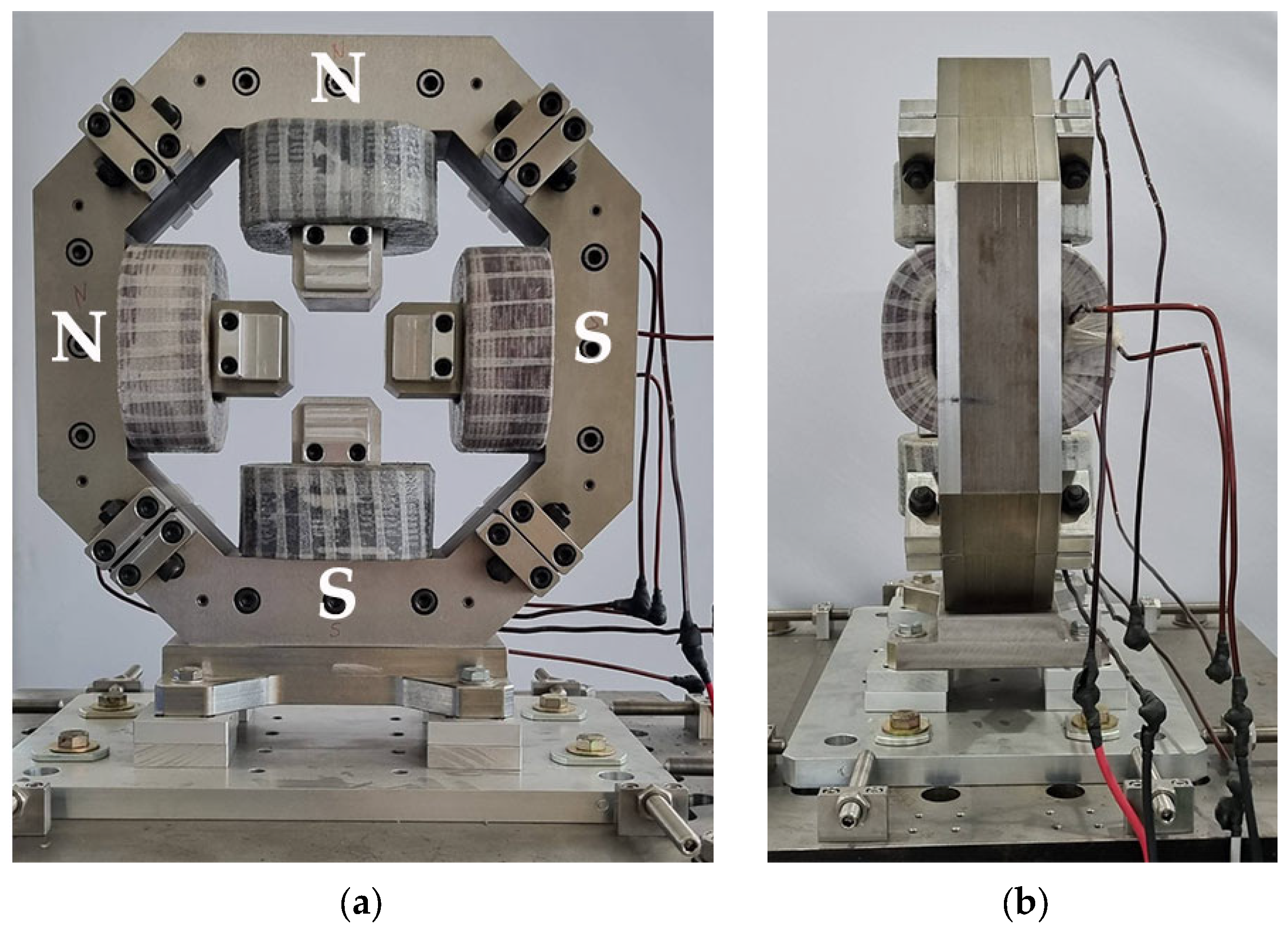
Computational structural analysis was performed using finite element methods in both SOLIDWORKS [15] and ANSYS [28] simulation software. Static deformation took into account the gravitational force of the magnet core and coil (94 kg), as well as the magnetic force of attraction between poles (67 N), during maximum excitation. This resulted in a maximum total deformation of 0.85 μ m , as shown in Figure 6a. The deformation was minimal, indicating the magnet core’s robust structural design. Coupled electromagnetic, heat transfer, and mechanics co-simulations were carried out using Opera-3D [26], as depicted in Figure 7. The impact of heat transfer at maximal excitation was negligible in terms of heat generation and did not contribute additional mechanical deformation. In terms of heat transfer enhancement, air cooling proved to be sufficient. In the absence of a stainless steel end support structure, Figure 7b shows that deformation could be as high as 1.67 μ m . The stainless steel support structure effectively maintained the magnet’s shape, even at the power supply’s maximum 30 A current.
Figure 6b illustrates the vibrational analysis conducted to investigate the magnet’s natural frequency, to prevent the potential disaster of coinciding vibration with forced frequency, which could result in resonance. The structure’s eigenmodes were solely determined by the magnet’s material and design. The most crucial eigenmode, the first-mode natural frequency, was calculated to be 176.95 Hz. In Figure 6b, both front and side views illustrate the impact of first-mode resonance, which was exaggerated by a factor of 2.4. Side-view vibration was expected to have the most significant impact. Forced frequencies could have originated from sources both internal and external to the building infrastructure, such as traffic noise, a cooling water pump, a vacuum pump, air conditioning, a chiller, or main’s electricity. Table 1 lists the sources of potential vibration, where the highest frequency of disturbance is 100 Hz.

5. Manufacturing

The COR-HV (COR-1 and COR-2) prototype magnet, as shown in Figure 8, was laminated to mitigate eddy current and curtail power loss. The magnet core material was crafted from ThyssenKrupp silicon steel sheets, a class of non-grain-oriented electrical silicon steel with low hysteresis loss. The 1 mm thick laminations were insulated on both sides. To achieve high precision, within a tolerance of ±0.020 mm, wire cutting was employed using an electrical discharge machine (EDM) for the laminated core. On assembling 50 silicon sheets, the physical magnet length was slightly longer than 50 mm. The end plates, which encapsulated the silicon steel sheets, were constructed from 15 mm thick SUS304 stainless steel using the same fabrication method. Notably, the stainless steel had no impact on the magnetic field, but enhanced overall structural integrity. The assembly process involved stacking and fastening using nuts, bolts, and locating pins, with four assemblages.
The coil conductor consisted of enamel-coated copper wire with dimensions specified in Table 3. To ensure safety, coils were insulated using fiberglass tape and impregnated with insulation varnish or epoxy resin. The COR-HV was air-cooled.

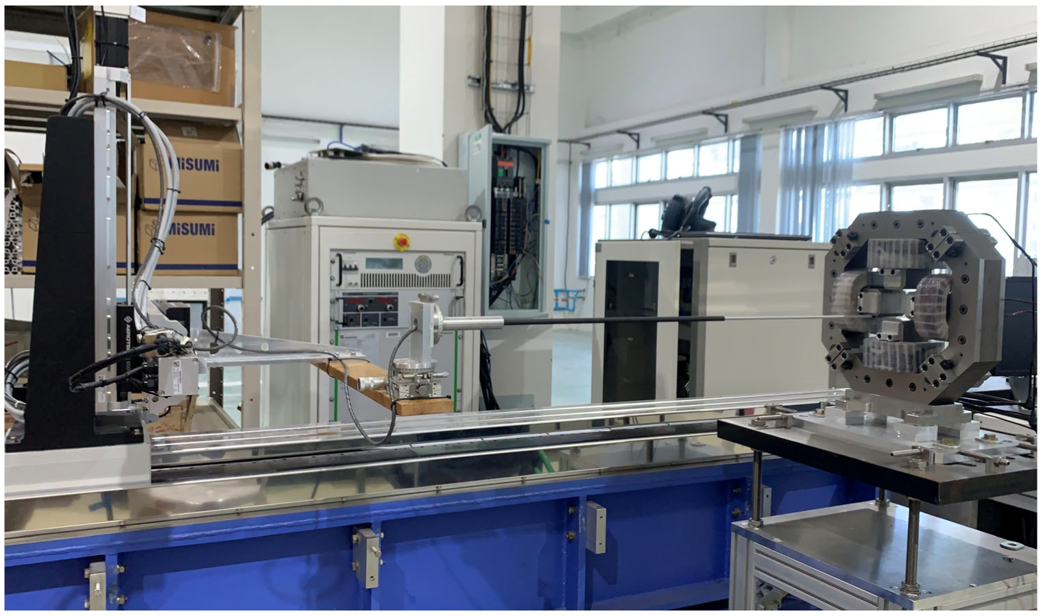
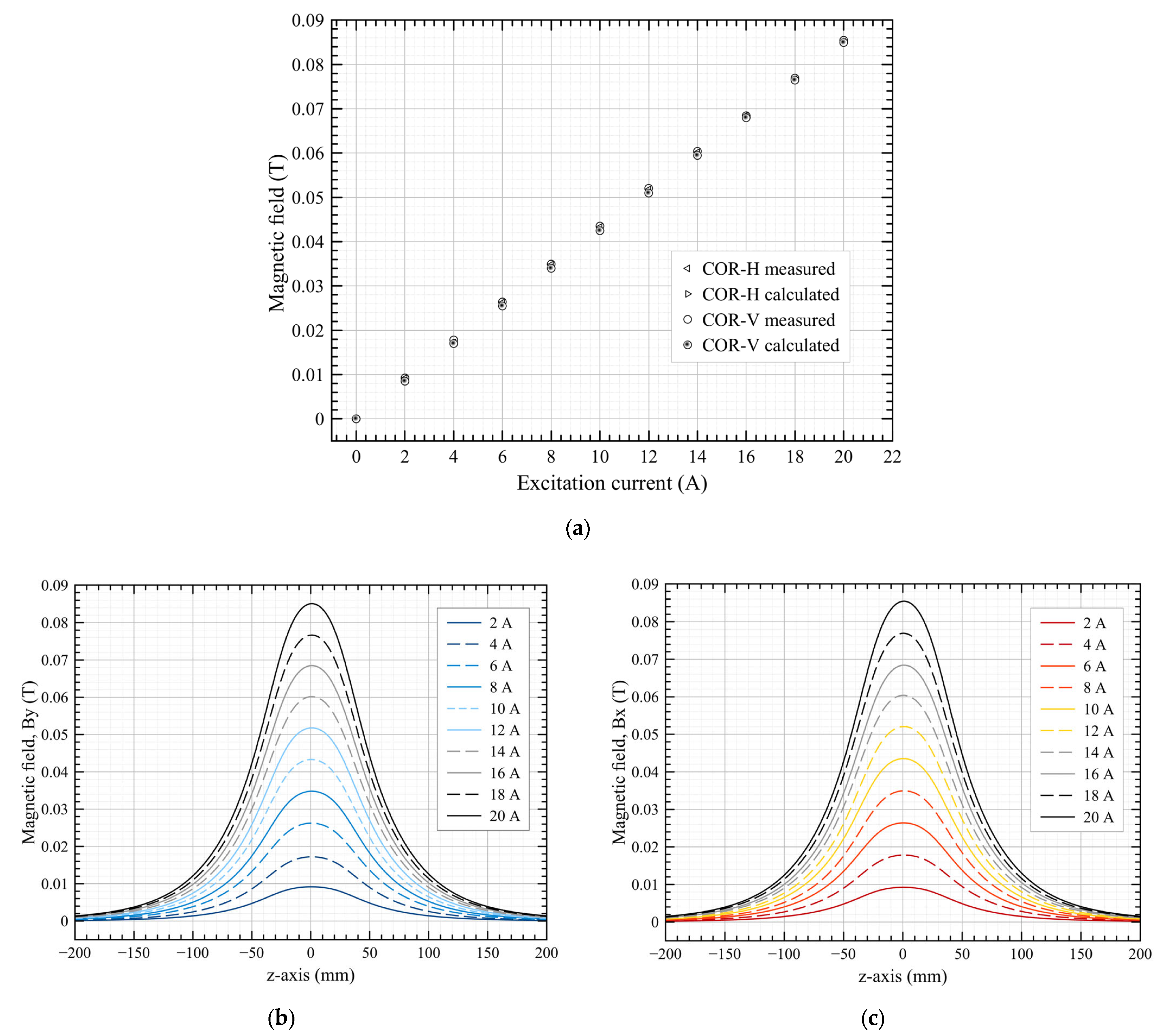
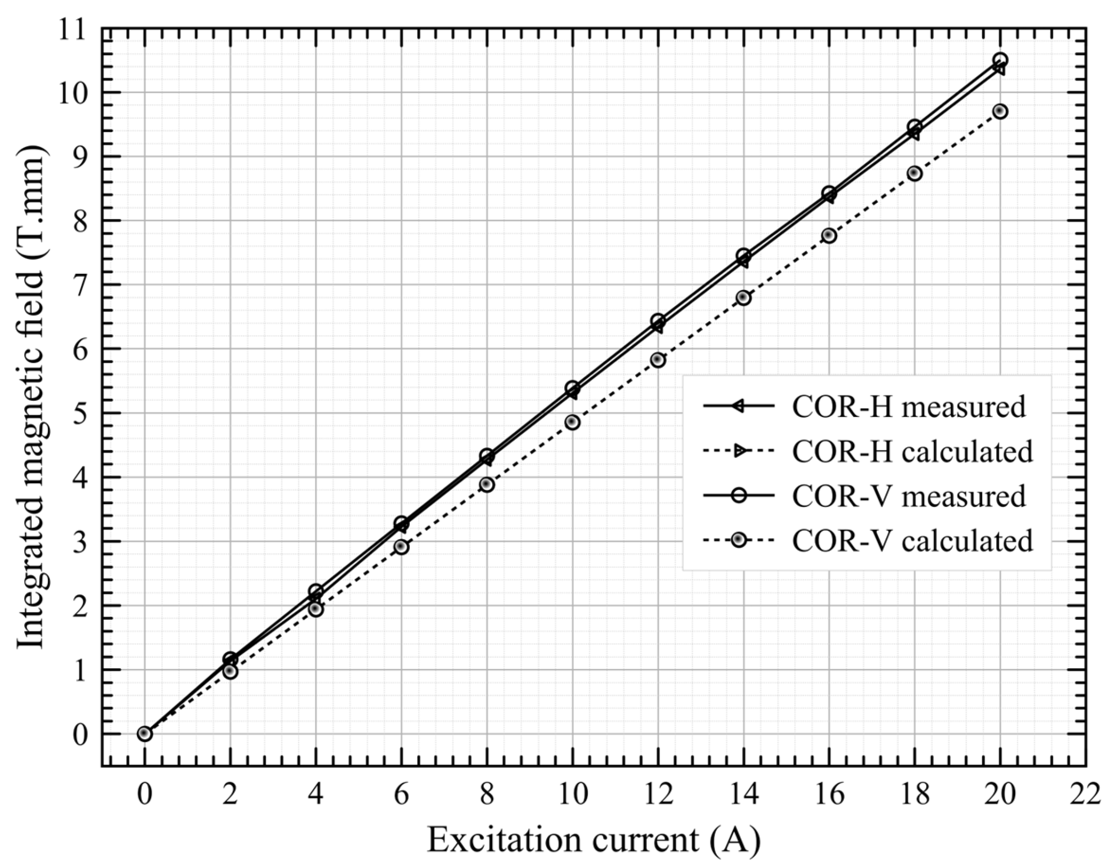
6. Magnetic Field Measurement

Figure 9 illustrates the Hall probe bench setup for magnetic field measurement. Alignment between the Hall probe bench and the magnet was achieved using a laser tracker and auto-level high-precision apparatus.
Figure 10a shows the results of the COR-H and COR-V magnetic fields in the XY-plane (at coordinate (x,y,z) = (0,0,0) mm); both measured and calculated magnetic fields are plotted against current. The discrepancy between calculated and measured results was less than 0.2%. Importantly, the magnetic field–excitation current curves exhibited linearity. Figure 10b,c illustrate the COR-H and COR-V magnetic fields along the magnet’s length ( 200 z 200   m m , in 2 mm increments) for all current values, respectively. The results presented in Figure 10b,c were used for the magnetic field integral, as shown in Figure 11, which compares calculated and measured values. At an 18 A excitation current, the magnetic field integral for COR-H was 9.31 Tesla.mm, while for COR-V it was 9.46 Tesla.mm, based on measurement data. The measured field integral was higher than the calculated integral, which was attributed to three factors: a discrepancy in the B–H curve used for calculation versus actual measurements, a magnet core with a slightly longer physical length, and the omission of eddy current effects from the simulation model. In future experiments, rotating coil and stretched wired instrumentations will be employed to take direct magnetic field integral measurements.

7. Conclusions

A combined horizontal and vertical correcting magnet prototype for the SPS-II storage ring was designed to maintain the electron beam in an ideal orbit. Magnetic field integral calculations were conducted using Opera-3D; the mechanical designs for static deformation and modal analysis were developed using SOLIDWORKS and ANSYS. The magnet core was successfully manufactured using silicon-laminated steel sheets with a tolerance of ±0.020 mm. The calculated and measured magnetic field results were in agreement within a 0.2% discrepancy. In retrospect, rotating coil or stretched wire apparatus could have been employed as an alternative Hall probe for magnetic field integral measurement.

Author Contributions

Conceptualization and methodology, S.P. and P.S. (Prapaiwan Sunwong); concepts regarding GOFB, S.K. (Sukho Kongtawong); Opera-3D software, P.S. (Prapaiwan Sunwong), W.T. and P.N.; SOLIDWORKS and ANSYS software, P.S. (Pariwat Singthong) and T.L.; validation, P.N., A.K., V.S. and W.T.; investigation, S.P. and P.S. (Prapaiwan Sunwong); writing—original draft preparation, S.P. and W.T.; supervision, S.K. (Supat Klinkiew). All authors have read and agreed to the published version of the manuscript.

Funding

This research was funded by the Science, Research, and Innovation Fund (SRI fund).

Data Availability Statement

Data presented in this study are available on request from the corresponding author.

Acknowledgments

The authors acknowledge Wiwek Phacheerak for knowledge contribution regarding the power supply system and Natthawut Suradet for his contribution to writing the control system code that measures the magnetic field’s AC excitation.

Conflicts of Interest

The authors declare no conflict of interest.

References

  1. Klysubun, P.; Pulampong, T.; Sudmuang, P. Design and Optimization of SPS-II storage ring. In Proceedings of the 13th International Particle Accelerator Conference, Copenhagen, Denmark, 14–19 May 2017; pp. 2773–2775, ISBN 978-3-95450-182-3. [Google Scholar]
  2. Wiedemann, H. Particle Accelerator Physics, 4th ed.; Springer: Berlin/Heidelberg, Germany, 2007; pp. 140, 230, 494–499. ISBN 978-3-540-49043-2. [Google Scholar]
  3. Hubert, N.; Cassinari, L.; Denard, J.-C.; Nadji, A.; Nadolski, L. Global Orbit Feedback Systems down to DC Using Fast and Slow Correctors. In Proceedings of the 9th European Workshop on Beam Diagnostics and Instrumentation for Particle Accelerators, Basel, Switzerland, 25–27 May 2009; pp. 27–31. [Google Scholar]
  4. Hubert, N.; Cassinari, L.; Denard, J.-C.; Leclercq, N.; Nadji, A.; Nadolshi, L.; Pedeau, D. The SOLEIL BPM and Orbit Feedback Systems. In Proceedings of the 8th European Workshop on Beam Diagnostics and Instrumentation for Particle Accelerators, Venice, Italy, 20–23 May 2007; Abstract Number TUPC20. pp. 189–191. [Google Scholar]
  5. Schilcher, T.; Boge, M.; Keil, B.; Schlott, V. Commissioning of the Fast Orbit Feedback at SLS. In Proceedings of the 2003 Particle Accelerator Conference, Portland, OR, USA, 12–16 May 2003; ISBN 0-7803-7738-9. [Google Scholar]
  6. Boge, M.; Keil, B.; Krempasky, J.; Schilcher, T.; Schlott, V. Orbit Stability at the SLS; PSI Scientific and Technical Report; Paul Scherrer Institut: Villigen, Switzerland, 2003; Volume 4, pp. 11–13. [Google Scholar]
  7. Plouviez, E.; Uberto, F. The Orbit Correction Scheme of the new EBS of the ESRF. In Proceedings of the International Beam Instrumentation Conference IBIC 2016, Barcelona, Spain, 11–15 September 2016; pp. 51–54, ISBN 978-3-95450-177-9. [Google Scholar]
  8. Tanaka, H.; Aoyagi, H.; Daté, S.; Fukami, K.; Fukui, T.; Kudo, T.; Kumagai, N.; Matsui, S.; Nakatani, T.; Nakazato, T.; et al. Beam Orbit Stabilization at the Spring-8 Storage Ring. In Proceedings of the 7th International Workshop on Accelerator Alignment 2002, Nishi-Harima, Japan, 11–14 November 2002; pp. 1–8. [Google Scholar]
  9. Kongtawong, S.; Tian, Y.; Yu, L.H.; Yang, X.; Wang, G.; Ha, K.; Shaftan, T. Numerical Simulation of NSLS-II Fast Orbit Feedback System. Nucl. Instrum. Methods Phys. Res. Sect. A 2021, 997, 165175. [Google Scholar] [CrossRef]
  10. Brañas, B.; Castellanos, J.; Oliver, C.; Campmany, J.; Fernández, F.; García, M.; Kirpitchev, I.; Marcos, J.; Massana, V.; Mendez, P.; et al. Design and manufacturing of the combined quadrupole and corrector magnets for the LIPAc accelerator high energy beam transport line. Nucl. Fusion 2022, 62, 086024. [Google Scholar] [CrossRef]
  11. Klute, J.; Duhme, H.T.; Balewski, K.; Tiessen, H.; Wierzcholek, F. The Petra III Fast Orbit Feedback System. In Proceedings of the 10th European Workshop on Beam Diagnostics and Instrumentation for Particle Accelerators, Hamburg, Germany, 16–18 May 2011; pp. 221–223. [Google Scholar]
  12. Giachero, A.F.; Bruno, G.B.M.; Russo, L.M.; Tavares, D.O. Fast Orbit Corrector Power Supply in MTCA.4 Form Factor for Sirius Light Source. In Proceedings of the 12th International Particle Accelerator Conference, Campinas, Brazil, 24–28 May 2021; JACoW Publishing: Geneva, Switzerland, 2021. [Google Scholar] [CrossRef]
  13. Kallakut, P.; Carwardine, J.; Brill, A.; Sereno, N. Closed Loop Modeling of the APS-U Orbit Feedback System. In Proceedings of the North American Particle Accelerator Conference 2019, Lansing, MI, USA, 2–6 September 2019; JACoW Publishing: Geneva, Switzerland, 2019. [Google Scholar] [CrossRef]
  14. Tsoupas, N.; Berg, J.S.; Brooks, S.; Jain, A.; M’eot, F.; Mahler, G.; Trabocchi, S.; Trbojevic, D.; Tuozzolo, J. The Dipole Corrector Magnets for the FFAG Beam Line of the CBETA Accelerator; Brookhaven National Laboratory: Upton, NY, USA, 2019. [Google Scholar] [CrossRef]
  15. Yu, M.; Velev, G.; Harding, D. Dipole Corrector Magnets for the LBNE Beam Line. In Proceedings of the 2011 Particle Accelerator Conference, New York, NY, USA, 28 March–1 April 2011. [Google Scholar]
  16. Kashikhin, V.S.; Carson, J.A.; Harding, D.J.; Lackey, J.R.; Makarov, A.; Pellico, W.; Prebys, E.J. A New Correction Magnet Package for the Fermilab Booster Synchrotron. In Proceedings of the 2005 Particle Accelerator Conference, Knoxville, TN, USA, 16–20 May 2005; IEEE: Piscataway, NJ, USA, 2005. [Google Scholar] [CrossRef]
  17. Lonza, M.; Bulfone, D.; Forchi, V.; Gaio, G.; Pivetta, L. A Fast Orbit Feedback for the ELETTRA Storage Ring. In Proceedings of the 2007 International Conference on Accelerator and Large Experimental Physics Control Systems, Knoxville, TN, USA, 15–19 October 2007. [Google Scholar]
  18. Steier, C.; Biocca, A.; Domning, E.; Jacobson, S. Commissioning Results of the Fast Orbit Feedback at the ALS. In Proceedings of the 2003 Particle Accelerator Conference, Portland, OR, USA, 12–16 May 2003; IEEE: Piscataway, NJ, USA, 2004; pp. 3374–3376. [Google Scholar] [CrossRef]
  19. Boge, M.; Dehler, M.; Schilcher, T.; Schlott, V.; Ursic, R. Fast Closed Orbit Control in the SLS Storage Ring. In Proceedings of the 1999 Particle Accelerator Conference, New York, NY, USA, 27 March–2 April 1999; pp. 1129–1131. [Google Scholar] [CrossRef]
  20. Corbett, W.; Hettel, R.; Akre, R.; Bellomo, P.; Boyce, R.; Cadapan, L.; Cassel, R.; Choi, B.; Dell’Orco, D.; Evans, I.; et al. Spear 3 Upgrade Project: A Status Report. In Proceedings of the 2001 Particle Accelerator Conference, Chicago, IL, USA, 18–22 June 2001; pp. 2674–2676, ISBN 1-4244-0917-9. [Google Scholar]
  21. Smith, S.L.; Hill, S.L. Daresbury SRS Positional Feedback Systems. In Proceedings of the 4th European Workshop on Beam Diagnostics and Instrumentation for Particle Accelerator, Chester, UK, 16–18 May 1999; CT05. pp. 64–66. [Google Scholar]
  22. Brunelle, P.; Besson, J.-C.; Cassinari, L.; Cousin, J.-M.; Darpentigny, J.; Flynn, G.; Girault, F.; Lamarre, J.-F.; Nadji, A.; Rieul, B.; et al. News on Beam Dynamics at Super-Aco. In Proceedings of the 1999 Particle Accelerator Conference, New York, NY, USA, 27 March–2 April 1999; IEEE: Piscataway, NJ, USA, 1999. [Google Scholar] [CrossRef]
  23. Otter, A.J.; Reeve, P.A. Combined AC Corrector Magnets. In Proceedings of the 1993 Particle Accelerator Conference, Washington, DC, USA, 17–20 May 1993; IEEE: Piscataway, NJ, USA, 2002. [Google Scholar] [CrossRef]
  24. Nadolski, L.S.; Besson, J.-C.; Bouvet, F.; Brunelle, P.; Cassinari, L.; Denard, J.-C.; Filhol, J.-M.; Hubert, N.; Lamarre, J.-F.; Loulergue, A.; et al. Orbit Stability Status and Improvement at SOLEIL. In Proceedings of the 11th European Particle Accelerator Conference, Genoa, Italy, 23–27 June 2008. [Google Scholar]
  25. Opera-3d 18R2: Reference Manual; Dassault Systèmes UK Ltd.: Kidlington, UK, 2018; pp. 1–918.
  26. SOLIDWORKS Premium 2021 SP5.1 Online Help; Dassault Systèmes SOLIDWORKS Corp.: Waltham, MA, USA, 2021.
  27. Nunes, S.A.; Chadebec, O.; Kuo-Peng, P.; Dular, P.; Cucco, B. Contribution on the Source Field Calculation through the Biot-Savart Equation Using Curvilinear Elements and an Adaptive Process. Prog. Electromagn. Res. C 2018, 88, 145–161. [Google Scholar]
  28. ANSYS Workbench 2020 R2 Documentation; ANSYS Inc.: Canonsburg, PA, USA, 2020.
Figure 1. Half of the double–triple bend achromat lattice for the SPS-II storage ring. The magnet colours indicate the magnet types: dark blue for dipole, red for quadrupole, purple for combined dipole, green for sextupole, yellow for octupole, and light blue for the combined horizontal and vertical correcting magnet.
Particles 06 00058 g001
Figure 2. Magnet pole and yoke of the combined horizontal and vertical correcting magnet: CAD design in (a) isometric view, (b) front view, and (c) side view.
Particles 06 00058 g002
Figure 3. Relationship between kick angle and AC excitation current.
Particles 06 00058 g003
Figure 4. Model of the combined horizontal and vertical correcting magnet and magnetic field contours obtained using Opera-3D.
Particles 06 00058 g004
Figure 5. Magnetic flux density obtained using Opera-3D (at z = 0 mm) for (a) the horizontal correcting magnet; (b) the vertical correcting magnet; and (cf) the combined correcting magnet with the direction of currents in four coil permutations. Red arrows illustrate the vector direction of the magnetic flux; white arrows indicate the vector direction of the force exerted on electron beam.
Particles 06 00058 g005aParticles 06 00058 g005b
Figure 6. ANSYS results of the combined horizontal and vertical correcting magnet with stainless steel end supports at maximum excitation for (a) static deformation and (b) first eigen-frequency modal analysis display at 2.4× scale.
Particles 06 00058 g006
Figure 7. Opera-3D results of the combined horizontal and vertical correcting magnet without stainless steel support for (a) temperature distribution, (b) static deformation, and (c) von Mises stress.
Particles 06 00058 g007
Figure 8. Prototype of the combined horizontal and vertical correcting magnet from (a) front view and (b) side view.
Particles 06 00058 g008
Figure 9. Hall probe bench for magnetic field measurement.
Particles 06 00058 g009
Figure 10. (a) Magnetic field in the XY-plane ((x,y,z) = (0,0,0)) vs. excitation current for COR-H and COR-V; (b) COR-H magnetic field (By (0,0,z)) measured along the azimuthal direction; and (c) COR-V magnetic field (Bx(0,0,z)) measured along the azimuthal direction.
Particles 06 00058 g010
Figure 11. Magnetic field integral vs. excitation current for COR-H and COR-V.
Particles 06 00058 g011
Table 1. Electron beam position perturbation sources and the amplitude of beam position shifts.
Perturbation/Noise SourcesFrequency (Hz) x r m s   ( μ m ) y r m s   ( μ m )
Air- and water-cooling temperature changes [3,6]0.00034-
Sun and moon tides [3]low-10–30
Experimental hall and ground vibration [3,5,7]1–100105
Booster ramp [3,5,7]1–100.600.35
Girder vibration mode [3]10–600.851.40
Power supply main [5]50 and 601.200.45
Power supply ripple [8]0.1–10, 30–40horizontal impact-
Insertion device parameter change [7]0.1–1--
Vacuum chamber vibration [8]20–70, 50–100horizontal impactvertical impact
Undefined [5]850.350.35
Table 2. Orbit correction feedback and corrector magnet types at synchrotron source facilities worldwide. These are listed in order of latest to oldest published results.
YearSR FacilityFB SchemeBandwidth (Hz)Core MaterialFabricationCorrector Type Stability   ( μ m )
2023SPS-IISOFB + FOFBSOFB (TBC)IronBlockCOR-HV + S0.27
2023SPS-IISOFB + FOFBFOFB (TBC)IronLamination (1 mm)COR-HV0.27
2021IFMIF [10]SOFBlowIronBlockQ + COR
2021NSLS-II [9]FOFBH (250–400), V (250–300)Air COR0.5
2021Petra III [11]FOFBDC-715Air COR
2021SIRIUS [12]SOFB + FOFBSOFB (DC-1)IronBlockCOR
2022SIRIUS [12]SOFB + FOFBFOFB (1000)IronLamination (0.5 mm)COR-H, COR-V
2019APS [13]FOFBDC-30, DC-50, 1000 *Air 8-pole COR<2, * <1
2019BNL [14]SOFBLowIronBlockQ + COR-H, Q + COR-V
2016ESRF [7]SOFB + FOFBSOFB (DC)IronBlockS + COR0.6
2016ESRF [7]SOFB + FOFBFOFB (DC-500)IronLaminationCOR0.6
2011FERMILAB [15]FOFB>15SteelLaminationCOR-H
2009SOLEIL [3]SOFB + FOFBSOFB (DC-0.02)IronBlockCOR
2009SOLEIL [3]SOFB + FOFBFOFB (DC-250)Air COR
2005FERMILAB [16]FOFB>15IronLamination (0.25 mm)COR-HV + NorSkQ+ NorSkS
2007ELETTRA [17]FOFBDC-70Air COR<0.2
2003ALS [18]FOFBDC-100, * (0.1–500)Iron + air ChicaneO < 1, * Hor. < 3, * Ver. < 2
2003SLS [6]SOFB + FOFBSOFB (<3)IronBlockCOR-H, COR-Vx < 1, y < 0.3
2003SLS [5,6,19]SOFB + FOFBFOFB (<100) COR-H, COR-Vx < 0.7, y < 0.06
2001SPEAR3 * [20]FOFBDC-100IronLaminationCOR-HVx < 20, y < 5
1999SRS [21]Local FB0.03IronBlockCOR-H, COR-V1
1999SUPER-ACO [22]FOFBDC-150Air Q + COR<5
1993TRIUMP [23]SOFBLowIronBlockCOR + Q + S
Notes: SR, synchrotron research; COR-H, horizontal corrector; COR-V, vertical corrector; COR-HV, combined horizontal and vertical corrector; S, sextupole magnet; *, an upgraded SR facility.
Table 3. Specifications of the combined horizontal and vertical correcting magnet.
ParameterValueUnit
Field integral8Tesla.mm
Effective length116.5mm
Physical length50mm
Magnet gap65mm
Coil turn number/pole140
Maximum DC current18A
Maximum AC current1A
Conductor size3 × 4 m m 2
Air-cooled magnet
Disclaimer/Publisher’s Note: The statements, opinions and data contained in all publications are solely those of the individual author(s) and contributor(s) and not of MDPI and/or the editor(s). MDPI and/or the editor(s) disclaim responsibility for any injury to people or property resulting from any ideas, methods, instructions or products referred to in the content.

