Shear at Fluid-Fluid Interfaces Affects the Surface Topologies of Alginate Microfibers


1
Department of Mechanical Engineering, Iowa State University, Ames, IA 50011, USA
2
Department of Biomedical Sciences, Iowa State University, Ames, IA 50011, USA
*
Author to whom correspondence should be addressed.
Clean Technol. 2019, 1(1), 265-272; https://doi.org/10.3390/cleantechnol1010018
Submission received: 11 July 2019
/
Revised: 5 August 2019
/
Accepted: 26 August 2019
/
Published: 2 September 2019
Abstract
:Hydrogel microfibers have great potential for applications such as tissue engineering or three-dimensional cell culturing. Their favorable attributes can lead to tissue models that can help to reduce or eliminate animal testing, thereby providing an eco-friendly alternative to this unsustainable process. In addition to their highly tunable mechanical properties, this study shows that varying the viscosity and flow rates of the prepolymer core solution and gellator sheath solution within a microfluidic device can affect the surface topology of the resulting microfibers. Higher viscosity core solutions are more resistant to deformation from shear force within the microfluidic device, thereby yielding smoother fibers. Similarly, maintaining a smaller velocity gradient between the fluids within the microfluidic device minimizes shear force and smooths fiber surfaces. This simple modification provides insight into manufacturing microfibers with highly tunable properties.
1. Introduction
Hydrogel-based microfibers have become promising tools in a variety of fields, such as tissue engineering and 3D cell culturing methods. Their favorable attributes stem from their high surface-to-area ratio, rapid diffusion gradients and strong potential for biocompatibility [1,2,3]. Their contributions to biomedical fields thus far have included the encapsulation or seeding of bioactive molecules [4,5], cells [1,6,7,8], or bacteria [9]; furthermore, their properties allow for the creation of a microenvironment that mimics conditions within the body, providing an extracellular-matrix (ECM) inspired scaffold for arranging and guiding cell growth, proliferation and differentiation [1,3,6,7].
By increasing the effectiveness and physiological relevancy of cell culture testing methods, microfiber-based scaffolds have the potential to drastically increase the sustainability of biomedical research and drug discovery practices. Three-dimensional cell culturing provides highly tunable microenvironments, thereby reducing or eliminating the need for animal testing in certain situations [10]. While animal testing has led to important breakthroughs thus far, its high consumption of energy, usage of harsh chemicals and production of waste are highly detrimental to the environment when used in such a large scale [11]. Scaffoldings provide a method of mass experimentation while utilizing drastically fewer material needs and operating at a higher efficiency, thereby increasing the sustainable development of biomedical research through this energy-friendly technology.
In particular, alginate microfibers provide highly biocompatible microscaffolds, which can be created with gentle, cell-safe methods, thereby enabling cell encapsulation and guidance. This FDA-approved polymer is biodegradable, and therefore lends itself well to long-term cell culture situations or sub-dermal tissue regeneration treatments [1,12,13]. Alginate microfibers are highly tunable, particularly when they are fabricated using the microfluidic technique, which is a powerful platform in a variety of applications [14,15,16,17,18]. For microfiber fabrication, one can utilize the interaction between a core alginate solution and a sheath solution to affect the size, shape, and mechanical properties of microfibers [1,19,20,21].
Changing the concentrations of the prepolymer core solution and the crosslinking sheath solution or adjusting the flow rate ratio (FRR), the ratio of the flow rates for the sheath and core solutions, can affect the mechanical properties and surface topologies of the fibers [1,19]. Furthermore, by adjusting the viscosity of the alginate solution and the velocity gradient at the fluid-fluid interface, it is possible to further adjust the properties of the fibers by changing their surface topology. This is of interest for applications where cell guidance is desired, such as culturing nerve cells for regenerative applications [12]. Micro-structures on the surface of hydrogels for cell culturing are known to affect their proliferation, differentiation, and behavior [3,7].
To highlight this feature of microfluidic microfiber fabrication, microfibers were fabricated with both filtered and non-filtered alginate solution, and their surface topologies were observed with SEM imaging. Filtered alginate solutions had a lower viscosity than the non-filtered solutions, which meant that they were more susceptible to deformation by the shear force applied from the sheath solution to the core solution. Two flow rate ratios (FRRs) were used, which allowed for observation of multiple core flow rates and sheath flow rates. A FRR of 50:10 µL/min:µL/min (sheath:core) will see a smaller velocity gradient at the fluid-fluid interface between the core and sheath fluids; therefore, the core solution will experience less shear force exhibited by the sheath solution. Conversely, a FRR of 75:5 µL/min:µL/min (sheath:core) will show a less stable regime.
2. Experiments
2.1. Creation of the Microfluidic Device and Solutions
Microfluidic devices were created by patterning polydimethylsiloxane (PDMS) with silicone-based photolithography molds. To create the microfluidic device, polydimethylsiloxane (PDMS) was cured at 80 °C for 20 min on a mold created through photolithography on a silicon wafer. The mold has been well documented—it has dimensions of 130 µm × 390 µm (height × width), and has four chevrons with dimensions of 130 µm × 100 µm, which are spaced 200 µm apart [1,6,19]. Once both halves of the mold were created, they were adhered using plasma cleaning.
To create the alginate solution, alginate (very low viscosity, Alfa Aesar, Ward Hill, MA, USA) was dissolved in deionized (DI) water at a concentration of 3.5% (w/v) with a magnetic stirrer at room temperature overnight. The filtered samples were created using a 3 µm pore size polytetrafluoroethylene (PTFE) syringe filter (Tisch Scientific, North Bend, OH, USA), then a 0.45 µm pore size polyvinyl difluoride (PVDF) syringe filter (Fisherbrand, Houston, TX, USA).
The sheath solution was created with 0.04% (w/v) CaCl2·2H2O (Fisher Chemical, Waltham, MA, USA) and 20% (w/v) poly (ethylene glycol) (PEG) (Mn = 20,000, Aldrich Chemistry, St. Louis, MO, USA). Fibers formed within the microfluidic device were gathered in a collection bath of 2.5% (w/v) CaCl2·2H2O, 16% (w/v) PEG to further solidify the fibers. PEG was added to the collection bath in order to change the specific gravity of the liquid, thereby allowing buoyant alginate microfibers to sink below the surface in order to increase the exposure to calcium ions within the 2.5% (w/v) CaCl2·2H2O solution.
2.2. Fabrication of Alginate Microfibers
To create microfibers, a double syringe pump (Cole-Parmer, Veron Hills, IL, USA) was used to control the core and sheath solution flow rates. While a variety of FRRs were tested during the optimization process, two representative FRRs are displayed here: 50:10 µL/min:µL/min and 75:5 µL/min:µL/min (sheath: core).
2.3. Viscosity Measurements
To measure the viscosity of filtered and unfiltered alginate solutions, a Canon-Fenske viscometer (350 727H, Cannon Instrument Company, State Collage, PA, USA) was suspended in a water bath maintained at 40 °C with a magnetic stirrer to ensure equal temperatures. A minimum of 6.5 mL of alginate solutions was loaded into the reservoir of the viscometer, and solutions were introduced into the efflux bulb via suction. A minimum of three samples were measured three times to ensure accuracy. The efflux time (the time required for the liquid line to fall between the starting point and the ending point) was then measured, and the kinematic viscosity was calculated using the following equation, where v is the kinematic viscosity, C is the viscometer constant, and t is the time required for the liquid to travel between the marked lines on the viscometer [22]:
2.4. SEM Imaging
To image the fibers, they were mounted onto paper frames, which were inserted into a JEOL JCM-6000 Benchtop Scanning Electron Microscope (SEM) using double-sided carbon tape (Nisshin EM.CO., LTD., Tokyo, Japan).
2.5. Profilometry Analysis
To quantitatively analyze the surface topology of alginate microfibers, a NewView 7100 Profilometer (Zygo, Middlefield, CT, USA) was used to image the surface of the fibers. Fibers were fabricated and allowed to dry for a minimum of one night; once dry, fibers were placed onto the flat profilometer stage and analyzed using the Zygo MetroPro system. Fibers were analyzed over the longitudinal axis, with readings taken parallel to the long length of the fibers. A minimum of five measurements were taken from a minimum of three locations along the fiber surface. For quantitative analysis, the Ra value, or the average roughness value, was used to compare samples. The Ra value is an average of the absolute value of surface difference when compared to the mean vertical value across the topography of a sample [23].
3. Results
The surface topology of alginate microfibers was readily tunable by adjusting the viscosity of the alginate core fluid, or by changing the FRR so that the velocity gradient between the core and sheath fluids is larger. In order to analyze the effect of viscosity on fiber surface topology, a 3.5% (w/v) alginate solution was used to fabricate fibers, and then the solution was filtered twice, thereby greatly reducing its viscosity. The results can be seen in Figure 1. In Figure 1a, more viscous unfiltered 3.5% (w/v) alginate microfibers were used as the prepolymer core fluid within the microfluidic device. With its higher viscosity, the core fluid was less affected by the shear force applied on the alginate solution by the ion-containing sheath solution. Therefore, the surface of the microfiber is smoother than the fibers fabricated with a lower viscosity alginate core solution, as seen in Figure 1b.
Furthermore, fibers fabricated with a higher velocity gradient can be observed in Figure 2. A FRR of 75:5 µL/min:µL/min (sheath: core) resulted in a higher amount of shear force from the sheath fluid to the core fluid, resulting in fibers with erratic surface topographies, even when using the higher-viscosity 3.5% (w/v) alginate core fluid. Attempting to utilize the less viscous filtered alginate solution resulted in a situation where microfibers could not be collected, either due to core fluid deformation to the point where no continuous fiber could be formed, or due to insufficient time within the microfluidic channel for solidification of the microfiber.
3.1. Viscosity Measurements
To understand how filtration changes fluid characteristics, kinematic viscosity measurements were carried out on the filtered and unfiltered alginate solutions. The average viscosity of unfiltered alginate solutions was 68.38 ± 0.74 cSt, whereas the average viscosity of filtered alginate solutions was 16.67 ± 1.52 cSt. Filtration removes larger particles, thereby reducing the overall viscosity.
3.2. Surface Topology
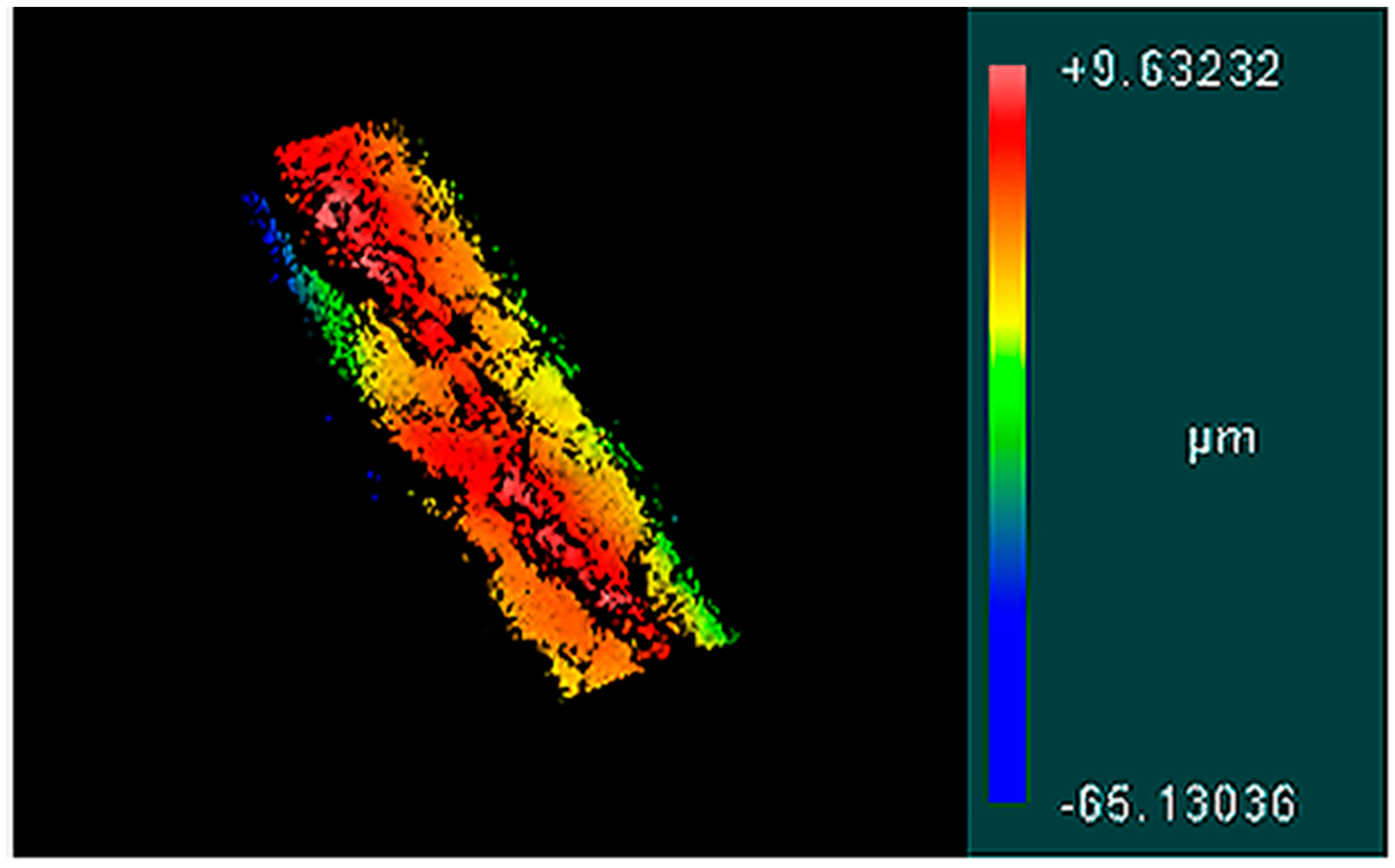
Profilometry analysis was used to quantitatively study the surface topologies of microfluidically created alginate microfibers. Profilometry analysis provided Ra measurements, which are equal to the mean of vertical deviations across the surface of the material. Ra measurements were taken along the surface of the microfibers along their longitudinal axis in order to determine the roughness of fibers generated with a variety of fabrication parameters; this data can be seen in Table 1. Figure 3 shows 3D surface images of fibers generated with a 50:10 µL/min:µL/min FRR, whereas Figure 4 shows data from a 75:5 µL/min:µL/min fiber.
4. Discussion
As past literature has suggested, there is a key relationship between the viscosity of the core fluid used within microfluidic microfiber fabrication techniques and the surface topologies of the resulting fibers [24]. This is due to higher viscosity fluids’ increased ability to withstand deformation due to shear force that arises within the microfluidic channel. In this study, core fluid viscosity was controlled by creating the desired concentration and filtering it, thereby yielding both a high and low viscosity sample. As expected, a higher viscosity core fluid resulted in a smoother fiber when compared to a lower viscosity core fluid fabricated at the same FRR, which can be quantitatively observed through profilometry measurements.
Similarly, velocity gradients between the core and sheath flow rates affect the amount of shear force exerted on the core fluid and can affect the surface topography of the resulting fiber. This can be observed in Figure 2, where a fiber made with a higher FRR exhibits a drastically rougher surface. Additionally, higher FRRs can create a regime wherein fibers cannot be fabricated, particularly when low viscosity prepolymer core fluids are being utilized. There has been some indication that the FRR also affects cell health for cases of cell encapsulation [1]. Interestingly, while the unfiltered core fluid microfibers fabricated with a FRR of 50:10 µL/min:µL/min had surfaces that were significantly less rough than either of the other samples, there was no significant difference between the filtered 50:10 µL/min:µL/min and the unfiltered 75:5 µL/min:µL/min samples, indicating that in this situation the change in viscosity and the velocity gradient at the fluid-fluid interface produced similar vertical deviations across the fiber surfaces.
Highly tunable surface topography for hydrogel microfibers will be of particular interest in research endeavors where cells are being seeded onto the surface of microfibers, since surface topography is known to affect cell proliferation, differentiation, and overall health [3,6,7]. Cells are greatly affected by their microenvironment, and this simple method to modify microfiber surface topography can be utilized to provide an additional degree of control over the behavior of cells, adding another level of control in a powerful manufacturing process to create continuous and tunable hydrogel microfibers.
Author Contributions
Conceptualization, M.C.M.; Methodology, M.C.M.; Validation, M.C.M. and R.J.P.; Formal Analysis, M.C.M.; Investigation, M.C.M. and R.J.P.; Resources, N.N.H.; Data Curation, M.C.M. and R.J.P.; Writing—Original Draft Preparation, M.C.M.; Writing—Review & Editing, M.C.M., R.J.P., R.M., and N.N.H.; Visualization, M.C.M. and N.N.H.; Supervision, N.N.H.; Project Administration, R.M. and N.N.H.; Funding Acquisition, R.M. and N.N.H.
Funding
This work was supported by the Office of Naval Research (ONR) Grant N000141612246, and ONR Grant N000141712620. We also acknowledge the ISU Honor’s Program.
Acknowledgments
The authors thank Farrokh Sharifi for his help with microfluidic fiber fabrication and technical writing. Additionally, the authors thank Alex Wrede, Rajeendra Pemathilaka, Kelli Johnston, Amir Niaraki Asli and Jingshuai Guo for their support.
Conflicts of Interest
The authors declare no conflict of interest.
References
- McNamara, M.C.; Sharifi, F.; Okuzono, J.; Montazami, R.; Hashemi, N.N. Microfluidic Manufacturing of Alginate Fibers with Encapsulated Astrocyte Cells. ACS Appl. Bio Mater. 2019, 2, 1603–1613. [Google Scholar] [CrossRef]
- Sharifi, F.; Sooriyarachchi, A.C.; Altural, H.; Montazami, R.; Rylander, M.N.; Hashemi, N.N. Fiber Based Approaches as Medicine Delivery Systems. ACS Biomater. Sci. Eng. 2016, 2, 1411–1434. [Google Scholar] [CrossRef]
- McNamara, M.C.; Sharifi, F.; Wrede, A.H.; Kimlinger, D.F.; Thomas, D.-G.; Vander Wiel, J.B.; Chen, Y.; Montazami, R.; Hashemi, N.N. Microfibers as Physiologically Relevant Platforms for Creation of 3D Cell Cultures. Macromol. Biosci. 2017, 17, 1700279. [Google Scholar] [CrossRef]
- Shekarforoush, E.; Mendes, A.C.; Baj, V.; Beeren, S.R.; Chronakis, I.S. Electrospun Phospholipid Fibers as Micro-Encapsulation and Antioxidant Matrices. Molecules 2016, 22, 1708. [Google Scholar] [CrossRef]
- Lin, Y.-S.; Huang, K.-S.; Yang, C.-H.; Wang, C.-Y.; Yang, Y.-S.; Hsu, H.C.; Liao, Y.-J.; Tsai, C.-W. Microfluidic Synthesis of Microfibers for Magnetic-Responsive Controlled Drug Release and Cell Culture. PLoS ONE 2012, 7, e33184. [Google Scholar] [CrossRef]
- Sharifi, F.; Patel, B.B.; Dzuilko, A.K.; Montazami, R.; Sakaguchi, D.S.; Hashemi, N.N. Polycaprolactone Microfibrous Scaffolds to Navigate Neural Stem Cells. Biomacromolecules 2016, 17, 3287–3297. [Google Scholar] [CrossRef] [Green Version]
- Patel, B.B.; Sharifi, F.; Stroud, D.P.; McNamara, M.C.; Hashemi, N.N.; Sakaguchi, D.S. 3D Microfibrous Scaffolds Selectively Promotes Proliferation and Glial Differentiation of Adult Neural Stem Cells: A Platform to Tune Cellular Behavior in Neural Tissue Engineering. Macromol. Biosci. 2018, 17, 1800236. [Google Scholar]
- Ikeda, K.; Nagata, S.; Okitsu, T.; Takeuchi, S. Cell fiber-based three-dimensional culture system for highly efficient expansion of human induced pluripotent stem cells. Sci. Rep. 2107, 7, 2850. [Google Scholar] [CrossRef]
- Higashi, K.; Ogawa, M.; Fujimoto, K.; Onoe, H.; Miki, N. Hollow Hydrogel Microfiber Encapsulating Microorganisms for Mass-Cultivation in Open Systems. Micromachines 2017, 8, 176. [Google Scholar] [CrossRef]
- Antoni, D.; Burckel, H.; Josset, E.; Noel, G. Three-Dimensional Cell Culture: A Breakthrough in Vivo. Int. J. Mol. Sci. 2015, 16, 5517–5527. [Google Scholar] [CrossRef]
- Groff, K.; Bachli, E.; Lansdowne, M.; Capaldo, T. Review of Evidence of Environmental Impacts of Animal Research and Testing. Environments 2014, 1, 14–30. [Google Scholar] [CrossRef] [Green Version]
- Kang, E.; Choi, Y.Y.; Chae, S.-K.; Moon, J.-H.; Chang, J.-Y.; Lee, S.-H. Microfluidic Spinning of Flat Alginate Fibers with Grooves for Cell-Aligning Scaffolds. Adv. Mater. 2012, 24, 4271–4277. [Google Scholar] [CrossRef]
- Sun, T.; Li, X.; Shi, Q.; Wang, H.; Huang, Q.; Fukuda, T. Microfluidic spun alginate hydrogel microfbiers and their application in tissue engineering. Gels 2018, 4, 38. [Google Scholar] [CrossRef]
- Caplin, J.D.; Granados, N.G.; James, M.R.; Montazami, R.; Hashemi, N.N. Microfluidic Organ-on-a-Chip Technology for Advancement of Drug Development and Toxicology. Adv. Healthc. Mater. 2015, 4, 1426–1450. [Google Scholar] [CrossRef] [Green Version]
- Hashemi, N.; Lackore, J.M.; Sharifi, F.; Goodrich, P.J.; Winchell, M.L.; Hashemi, N.N. A paper-based microbial fuel cell operating under continuous flow condition. Technology 2016, 4, 98–103. [Google Scholar] [CrossRef] [Green Version]
- Pemathilaka, R.L.; Caplin, J.D.; Aykar, S.S.; Montazami, R.; Hashemi, N.N. Placenta-on-a-Chip: In Vitro Study of Caffeine Transport across Placental Barrier Using Liquid Chromatography Mass Spectrometry. Glob. Chall. 2019, 3, 180112. [Google Scholar] [CrossRef]
- Sechi, D.; Greer, B.; Johnson, J.; Hashemi, N.N. Three-Dimensional Paper-Based Microfluidic Device for Assays of Protein and Glucose in Urine. Anal. Chem. 2013, 85, 10733–10737. [Google Scholar] [CrossRef] [Green Version]
- Acar, H.; Cinar, S.; Thunga, M.; Kessler, M.R.; Hashemi, N.N.; Montazami, R. Study of Physically Transient Insulating Materials as a Potential Platform for Transient Electronics and Bioelectronics. Adv. Funct. Mater. 2014, 24, 4136–4143. [Google Scholar] [CrossRef]
- Sharifi, F.; Bai, Z.; Montazami, R.; Hashemi, N.N. Mechanical and physical properties of poly(vinyl alcohol) microfibers fabricated by a microfluidic approach. RSC Adv. 2016, 6, 55343–55353. [Google Scholar] [CrossRef] [Green Version]
- Bai, Z.; Mendoza Reyes, J.M.; Montazami, R.; Hashemi, N.N. On-chip development of hydrogel microfibers from round to square/ribbon shape. J. Mater. Chem. A 2014, 2, 4878–4884. [Google Scholar] [CrossRef] [Green Version]
- Lu, M.; Sharifi, F.; Hashemi, N.N.; Montazami, R. Fluid-Induced Alignment of Carbon Nanofibers in Polymer Fibers. Macromol. Mater. Eng. 2017, 302, 1600544. [Google Scholar] [CrossRef]
- Int’l, A. Standard Specifications and Operating Instructions for Glass Capillary Kinematic Viscometers; ASTM: Salt Lake City, UT, USA, 2009. [Google Scholar]
- Bhushan, B. Modern Tribology Handbook. In Modern Tribology Handbook; Bhushan, B., Ed.; CRC Press: Boca Raton, FL, USA, 2000; Volume 2, pp. 1413–1515. [Google Scholar]
- Shi, X.; Ostrovidov, S.; Zhao, Y.; Liang, X.; Kasuya, M.; Kurihara, K.; Nakajima, K.; Bae, H.; Wu, H.; Khademhosseini, A. Microfluidic Spinning of Cell-Responsive Grooved Microfibers. Adv. Funct. Mater. 2015, 25, 2250–2259. [Google Scholar] [CrossRef]
Figure 1.
SEM images of 3.5% (w/v) alginate microfibers created with a microfluidic device with a 0.04% (w/v) CaCl2·2H2O, 20% (w/v) poly (ethylene glycol) (PEG) sheath solution, and gathered into a 2.5% (w/v) CaCl2·2H2O, 16% (w/v) PEG collection bath. Each of these was fabricated with a flow rate ratio (FRR) of 50:10 µL/min:µL/min (sheath:core). (a1,a2) The unfiltered alginate core fluid provided a fiber with a smooth surface topology; (b1,b2) the filtered alginate core fluid was more greatly affected by shear force applied by the sheath solution, which thereby produced a microfiber with a rougher surface topology. (a1, b1) Fiber images with 300× magnification; (a2, b2) Fiber images with 650× magnification.

Figure 2.
SEM images of 3.5% (w/v) alginate microfibers created with a microfluidic device with 0.04% (w/v) CaCl2·2H2O, 20% (w/v) PEG sheath solution, and gathered into a 2.5% (w/v) CaCl2·2H2O, 16% (w/v) PEG collection bath. Each of these was fabricated with an FRR of 75:5 µL/min:µL/min (sheath:core). (a) Fiber at 300× magnification; (b) Fiber at 650× magnification.

Figure 3.
The 3.5% (w/v) alginate microfibers created with a microfluidic device with 0.04% (w/v) CaCl2·2H2O, 20% (w/v) PEG sheath solution, and gathered into a 2.5% (w/v) CaCl2·2H2O, 16% (w/v) PEG collection bath. Each of these was fabricated with an FRR of 50:10 µL/min:µL/min (sheath:core). (a) The unfiltered alginate core fluid provided a fiber with a smooth surface topology; (b) The filtered alginate core fluid was more greatly affected by shear force applied by the sheath solution, which thereby produced a microfiber with a rougher surface topology.
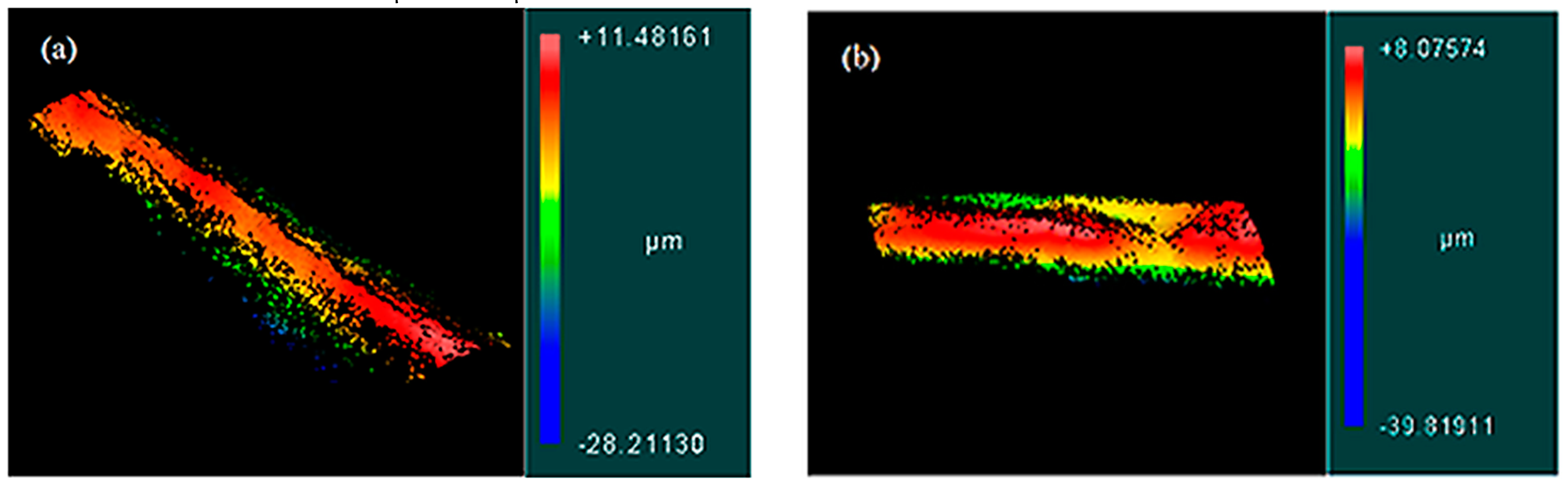
Figure 4.
The 3.5% (w/v) alginate microfibers created with a microfluidic device with 0.04% (w/v) CaCl2·2H2O, 20% (w/v) PEG sheath solution, and gathered into a 2.5% (w/v) CaCl2·2H2O, 16% (w/v) PEG collection bath. Each of these was fabricated with a FRR of 50:10 µL/min:µL/min (sheath:core).
Figure 4.
The 3.5% (w/v) alginate microfibers created with a microfluidic device with 0.04% (w/v) CaCl2·2H2O, 20% (w/v) PEG sheath solution, and gathered into a 2.5% (w/v) CaCl2·2H2O, 16% (w/v) PEG collection bath. Each of these was fabricated with a FRR of 50:10 µL/min:µL/min (sheath:core).

Table 1.
Average surface roughness (Ra) values for alginate microfibers fabricated using different FRRs and core fluid filtration techniques.
Table 1.
Average surface roughness (Ra) values for alginate microfibers fabricated using different FRRs and core fluid filtration techniques.
| FRRs (µL/min:µL/min) | Filtration | Ra (µm) |
|---|---|---|
| 50:10 | N/A | 1.294 ± 0.324 |
| 50:10 | 0.45 µm pore size | 2.35 ± 0.33 |
| 75:5 | N/A | 3.10 ± 0.58 |
© 2019 by the authors. Licensee MDPI, Basel, Switzerland. This article is an open access article distributed under the terms and conditions of the Creative Commons Attribution (CC BY) license (http://creativecommons.org/licenses/by/4.0/).
Share and Cite
MDPI and ACS Style
McNamara, M.C.; Pretzer, R.J.; Montazami, R.; Hashemi, N.N. Shear at Fluid-Fluid Interfaces Affects the Surface Topologies of Alginate Microfibers. Clean Technol. 2019, 1, 265-272. https://doi.org/10.3390/cleantechnol1010018
AMA Style
McNamara MC, Pretzer RJ, Montazami R, Hashemi NN. Shear at Fluid-Fluid Interfaces Affects the Surface Topologies of Alginate Microfibers. Clean Technologies. 2019; 1(1):265-272. https://doi.org/10.3390/cleantechnol1010018
Chicago/Turabian StyleMcNamara, Marilyn C., Ryan J. Pretzer, Reza Montazami, and Nicole N. Hashemi. 2019. "Shear at Fluid-Fluid Interfaces Affects the Surface Topologies of Alginate Microfibers" Clean Technologies 1, no. 1: 265-272. https://doi.org/10.3390/cleantechnol1010018