
A Scan-to-BIM Methodology Applied to Stone Pavements in Archaeological Sites

 ,
,  , , , ,
Abstract
:1. Introduction
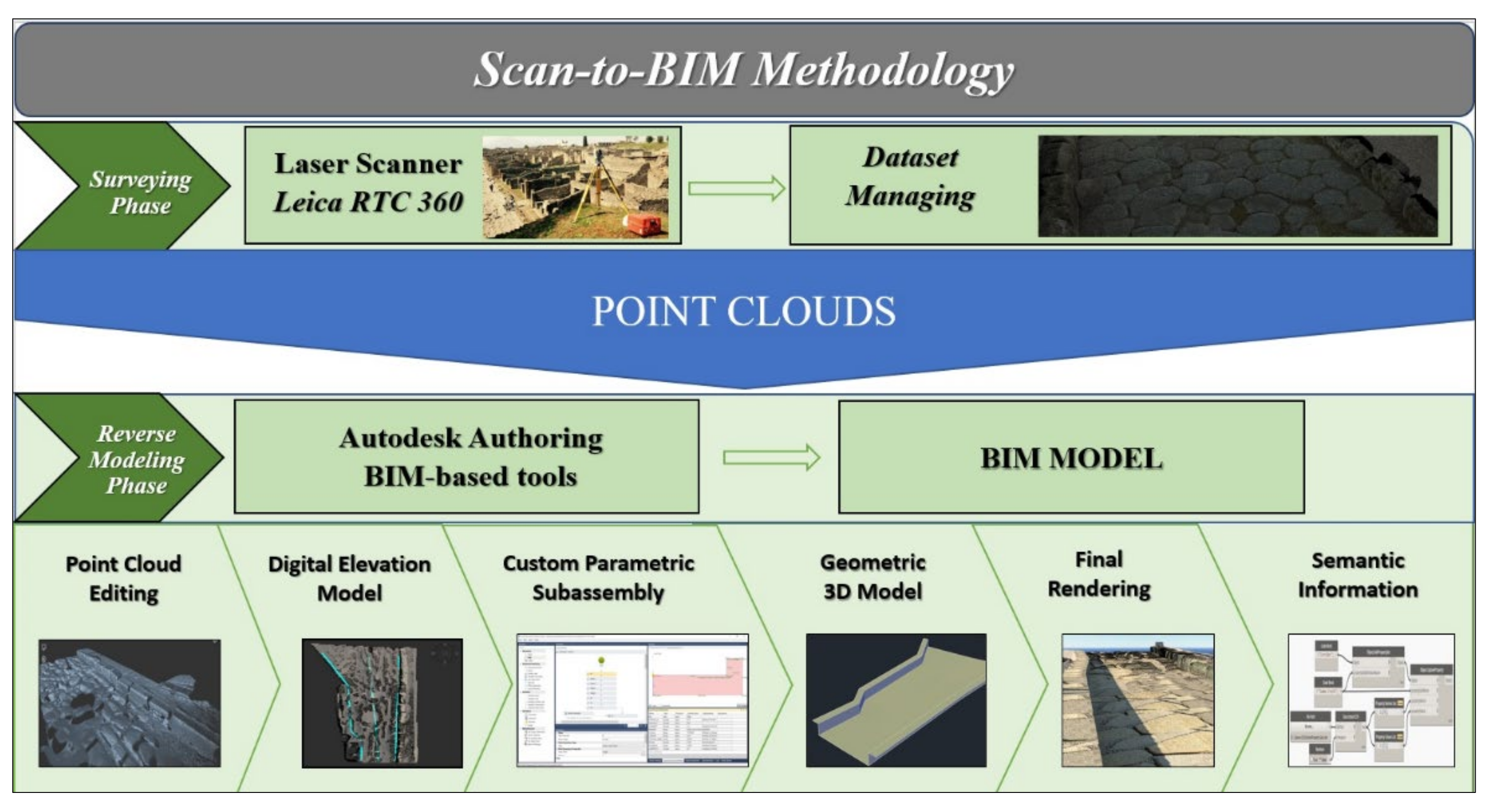
2. Methodology
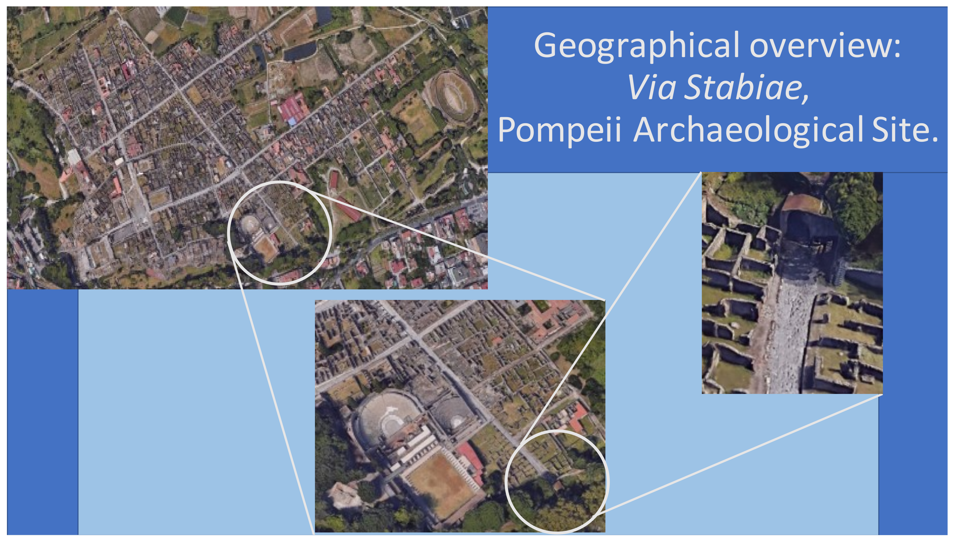
3. Case Study
3.1. Pompeii Case Study
3.2. Surveying Phase
3.3. Database Managing and Point Cloud Editing
3.3.1. Leica Cyclone Database Management
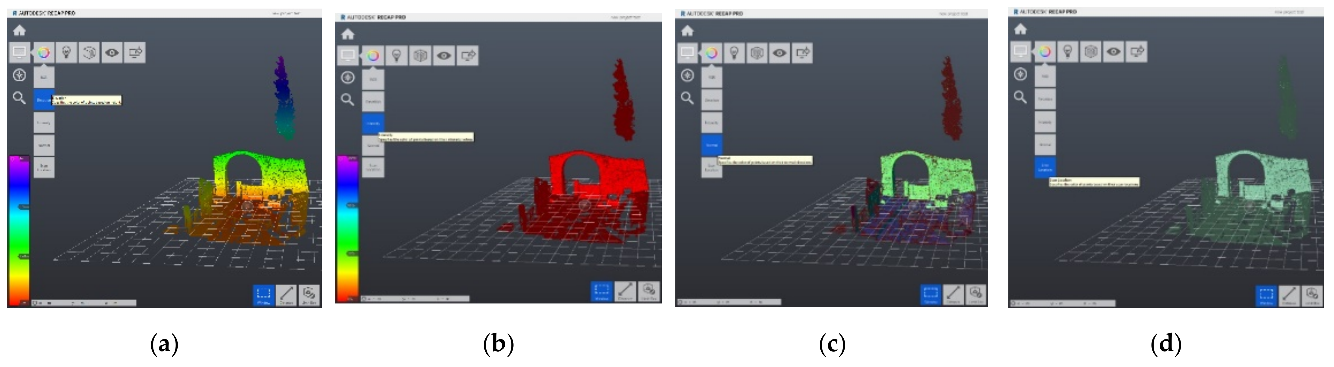
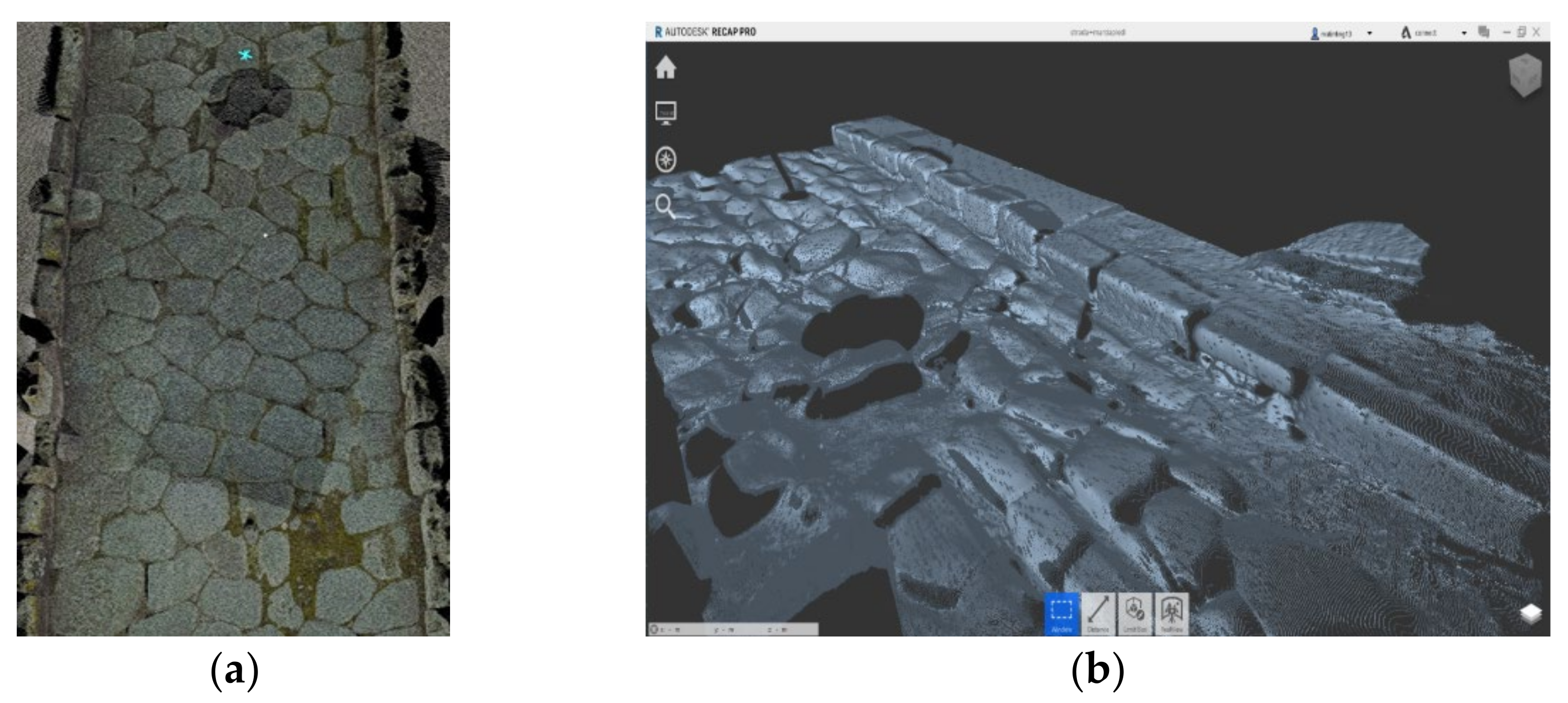
3.3.2. Autodesk Recap Pro Point Cloud Segmentation
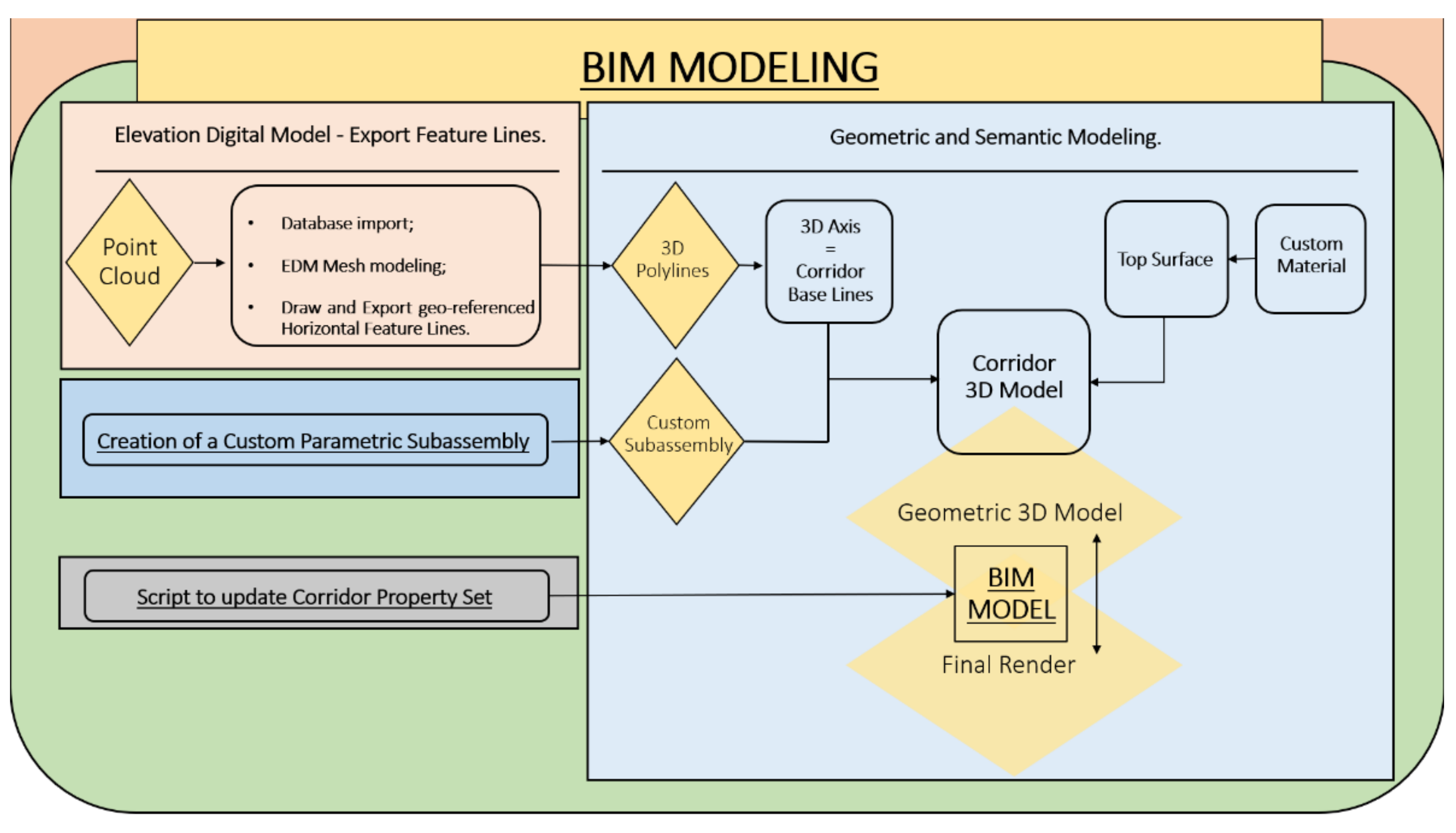
3.4. H-BIM Process
3.4.1. Infraworks DEM Creation
3.4.2. Subassembly Composer Custom Subassembly Modeling
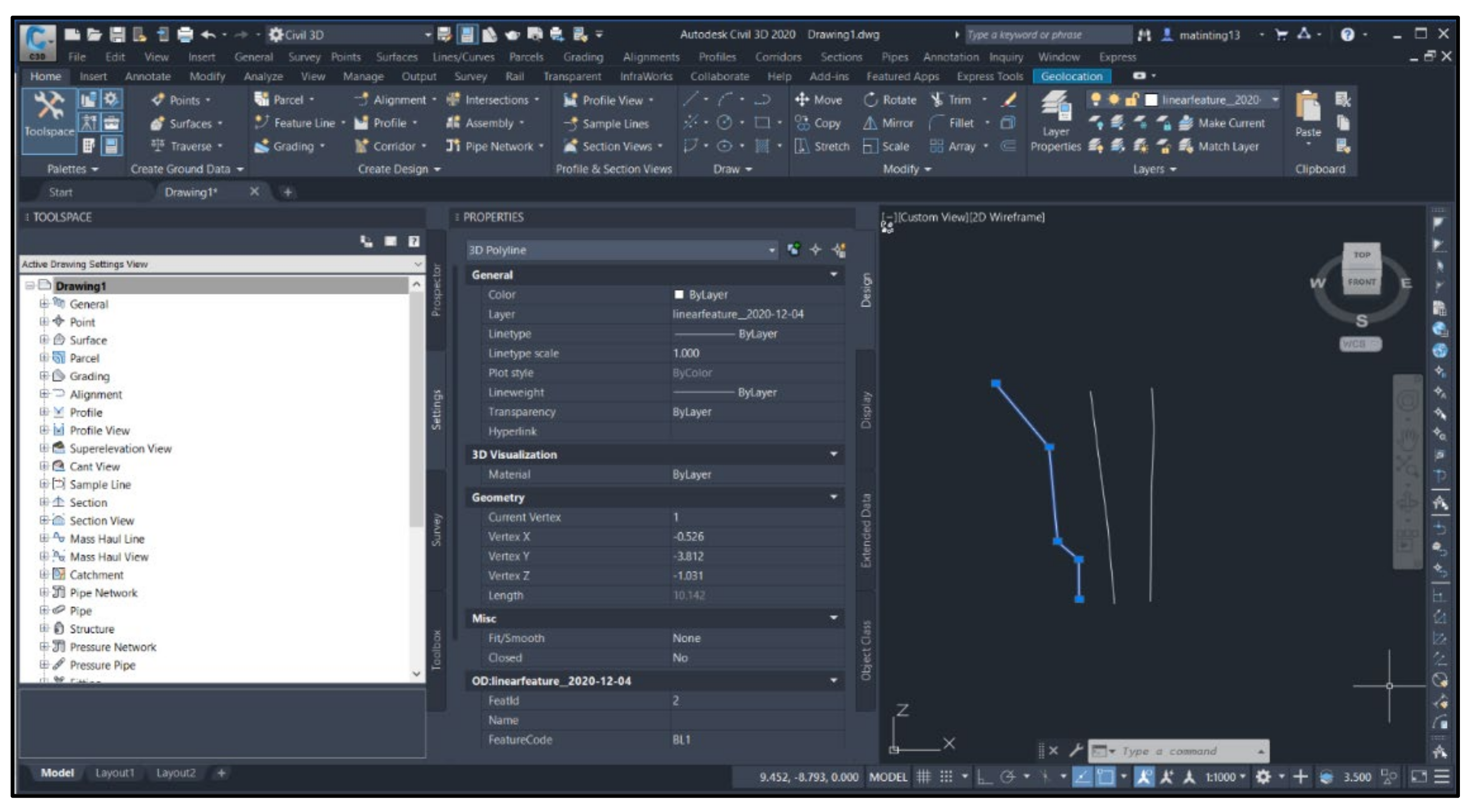
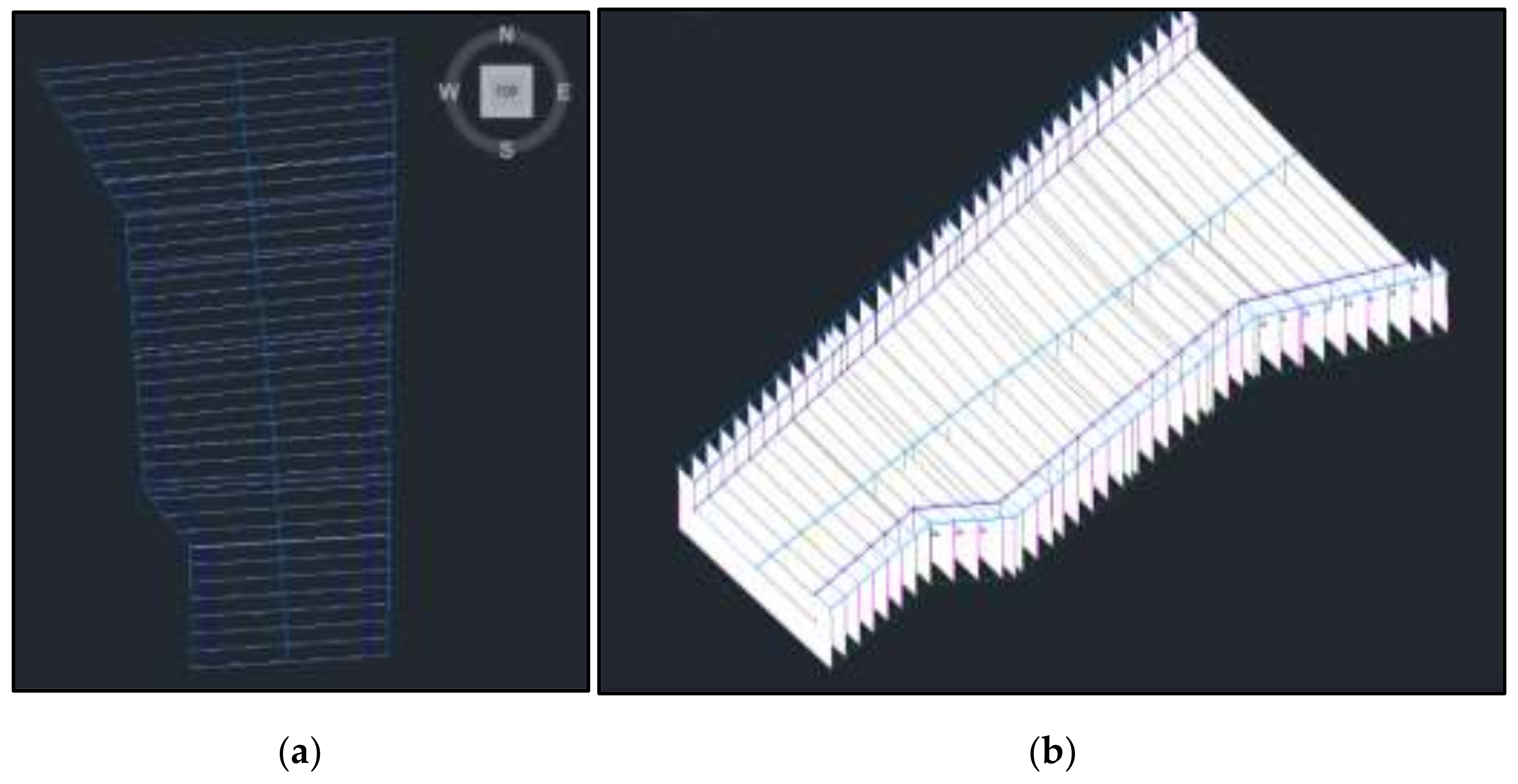
3.4.3. Civil 3D Corridor Modeling
3.4.4. Infraworks Rendering
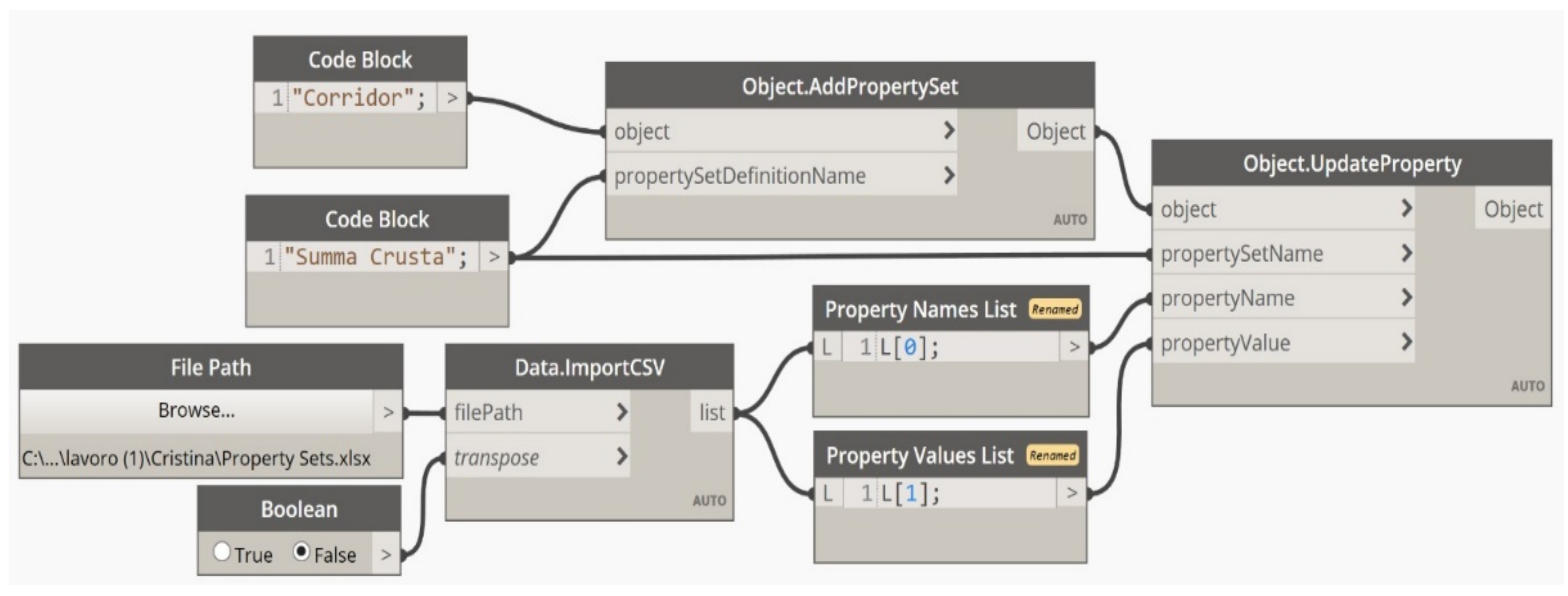
3.5. Algorithm Scripting through the Visual Programming Language Environment within Dynamo
4. Results
5. Discussion
6. Conclusions
Author Contributions
Funding
Institutional Review Board Statement
Informed Consent Statement
Data Availability Statement
Acknowledgments
Conflicts of Interest
References
- Kenley, R.; Harfield, T.; Behnam, A. BIM interoperability limitations: Australian and Malaysian rail projects. In Proceedings of the 4th International Building Control Conference 2016 (IBCC 2016), Kuala Lumpur, Malaysia, 7–8 March 2016. [Google Scholar] [CrossRef] [Green Version]
- Abbondati, F.; Biancardo, S.A.; Sicignano, G.; Guerra de Oliveira, S.; Tibaut, A.; Dell’Acqua, G. BIM parametric modelling of a railway underpass. Ing. Ferrov. 2020, 75, 443–459. [Google Scholar]
- Fabozzi, S.; Biancardo, S.A.; Veropalumbo, R.; Bilotta, E. I-BIM based approach for geotechnical and numerical modelling of a conventional tunnel excavation. Tunn. Undergr. Space Technol. 2021, 108, 103723. [Google Scholar] [CrossRef]
- Biancardo, S.A.; Intignano, M.; Viscione, N.; Guerra De Oliveira, S.; Tibaut, A. Procedural Modeling-Based BIM Approach for Railway Design. J. Adv. Transp. 2021, 2021, 8839362. [Google Scholar] [CrossRef]
- Azhar, S.; Khalifan, M.; Maqsood, T. Building Information Modeling (BIM): Now and Beyond. Constr. Econ. Build. 2012, 12, 15–28. [Google Scholar] [CrossRef] [Green Version]
- Charef, R.; Emmit, S.; Alaka, H.; Fouchal, F. Building Information Modelling adoption in the European Union: An overview. J. Build. Eng. 2019, 25, 100777. [Google Scholar] [CrossRef]
- Murphy, M.; McGovern, E.; Pavia, S. Historic building information modelling (HBIM). Struct. Surv. 2009, 27, 311–327. [Google Scholar] [CrossRef] [Green Version]
- Hichri, N.; Stefani, C.; De Luca, L.; Veron, P. Review of the As-Built Bim approaches. Int. Arch. Photogramm. Remote Sens. Spat. Inf. Sci. 2013, XL-5/W1, 107–112. [Google Scholar] [CrossRef] [Green Version]
- Fröhlich, C.; Mettenleiter, M. Terrestrial laser scanning—New perspectives in 3D surveying. Int. Arch. Photogramm. Remote Sens. Spat. Inf. Sci. 2004, 36, W2. [Google Scholar]
- Achille, C.; Adami, A.; Chiarini, S.; Cremonesi, S.; Francesco, F.; Fregonese, L.; Taffurelli, L. UAV-Based Photogrammetry and Integrated Technologies for Architectural Applications—Methodological Strategies for the After-Quake Survey of Vertical Structures in Mantua (Italy). Sensors 2015, 15, 15520–15539. [Google Scholar] [CrossRef] [Green Version]
- Stal, C.; Verbeurgt, J.; De Sloover, L.; De Wulf, A. Assessment of handheld mobile terrestrial laser scanning for estimating tree parameters. J. For. Res. 2021, 32, 1503–1513. [Google Scholar] [CrossRef]
- Micheletti, N.; Chandler, J.H.; Lane, S.N. Structure from Motion (SfM) Photogrammetry. InGeomorphological Techniques, Chap. 2, Sec. 2.2; British Society for Geomorphology Publishing: London, UK, 2015; ISSN 2047-0371. [Google Scholar]
- Turner, D.; Lucieer, A.; Watson, C. An Automated Technique for Generating Georectified Mosaics from Ultra-High Resolution Unmanned Aerial Vehicle (UAV) Imagery, Based on Structure from Motion (SfM) Point Clouds. Remote Sens. 2012, 4, 1392–1410. [Google Scholar] [CrossRef] [Green Version]
- Brumana, R.; Oreni, D.; Barazzetti, L.; Cuca, B.; Previtali, M.; Banfi, F. Survey and Scan to BIM model for the knowledge of built heritage and the management of conservation activities. In Digital Transformation of the Design, Construction and Management Processes of the Built Environment; Springer International Publishing: Berlin/Heidelberg, Germany, 2020. [Google Scholar] [CrossRef] [Green Version]
- Bitelli, G.; Balletti, C.; Brumana, R.; Barazzetti, L.; D’Urso, M.G.; Rinaudo, F.; Tucci, G. Metric documentation of cultural heritage: Research directions from the Italian GAMHer Project. In Proceedings of the International Archives of the Photogrammetry, Remote Sensing and Spatial Information Sciences, Volume XLII-2/W5, 2017 26TH International CIPA Symposium 2017, Ottawa, ON, Canada, 28 August–1 September 2017. [Google Scholar]
- Bruno, N.; Roncella, R. HBIM for Conservation: A New Proposal for Information Modeling. Remote Sens. 2019, 11, 1751. [Google Scholar] [CrossRef] [Green Version]
- Croce, V.; Caroti, G.; De Luca, L.; Jacquot, K.; Piemonte, A.; Véron, P. From the Semantic Point Cloud to Heritage-Building Information Modeling: A Semiautomatic Approach Exploiting Machine Learning. Remote Sens. 2021, 13, 461. [Google Scholar] [CrossRef]
- Andriasyan, M.; Moyano, J.; Nieto-Julian, J.E.; Anton, D. From Point Cloud Data to Building Information Modelling: An Automatic Parametric Workflow for Heritage. Remote Sens. 2020, 12, 1094. [Google Scholar] [CrossRef] [Green Version]
- Stanga, C.; Hasníková, H.; Previtali, M.; Brumana, R.; Grimoldi, A.; Banfi, F. The assessment of the baroque vault construction technique by Scan-To-BIM process, St. Bernard’s Chapel in the Plasy Monastery. Int. Arch. Photogramm. Remote Sens. Spat. Inf. Sci. 2019, XLII-2/W15, 1127–1134. [Google Scholar] [CrossRef] [Green Version]
- Apollonio, F.I.; Gaiani, M.; Fallavollita, F.; Ballabeni, M.; Zheng, S. Bologna Porticoes Project: 3D Reality-Based Models for the Management of a Wide-Spread Architectural Heritage Site. In Digital Heritage. Progress in Cultural Heritage: Documentation, Preservation and Protection. EuroMed; Ioannides, M., Magnenat-Thalmann, N., Fink, E., Žarnić, R., Yen, A.Y., Quak, E., Eds.; Lecture Notes in Computer Science; Springer: Cham, Switzerland, 2014; Volume 8740. [Google Scholar]
- Mandujano Rodríguez, M.G. Relationship between historic building information modeling and conventional valuation approaches for managing cultural heritage sites and its impact on tourism. J. Herit. Tour. 2014, 15, 381–397. [Google Scholar] [CrossRef]
- Cuca, B.; Agapiou, A.; Kkolos, A.; Hadjimitsis, D. Integration of Innovative Surveying Technologies for Purposes of 3D Documentation and Valorisation of St. Herakleidios Monastery in Cyprus. In Digital Heritage. Progress in Cultural Heritage: Documentation, Preservation and Protection. EuroMed; Ioannides, M., Magnenat-Thalmann, N., Fink, E., Žarnić, R., Yen, A.Y., Quak, E., Eds.; Lecture Notes in Computer Science; Springer: Cham, Switzerland, 2014; Volume 8740. [Google Scholar]
- Moyano, J.; Nieto-Julian, J.E.; Anton, D.; Cabrera, E.; Bienvenido-Huertas, D.; Sanchez, N. Suitability study of Structure-from-Motion for the Digitisation of Architectural (Heritage) spaces to apply divergent photograph collection. Symmetry 2020, 12, 1981. [Google Scholar] [CrossRef]
- Peña-Villasenín, S.; Gil-Docampo, M.; Ortiz-Sanz, J. 3-D Modeling of Historic Façades Using SFM Photogrammetry Metric Documentation of Different Building Types of a Historic Center. Int. J. Archit. Herit. 2017, 11, 871–890. [Google Scholar] [CrossRef]
- Capone, M.; Lanzare, E. Scan-to-BIM vs. 3D ideal model. Int. Arch. Photogramm. Remote Sens. Spat. Inf. Sci. 2019, XLII-2/W9, 219–226. [Google Scholar] [CrossRef] [Green Version]
- Dore, C.; Murphy, M. Current state of the art historic building information modelling. ISPRS—Int. Arch. Photogramm. Remote Sens. Spat. Inf. Sci. 2017, XLII-2/W5, 185–192. [Google Scholar] [CrossRef] [Green Version]
- Dore, C.; Murphy, M. Integration of Historic Building Information Modeling (HBIM) and 3D GIS for Recording and Managing Cultural Heritage Sites. In Proceedings of the 2012 18th International Conference on Virtual Systems and Multimedia, Milan, Italy, 2–5 September 2012; pp. 369–376. [Google Scholar]
- Murphy, M.; McGovern, E.; Pavia, S. Historic Building Information Modelling—Adding intelligence to laser and image based surveys of European classical architecture. ISPRS J. Photogramm. Remote Sens. 2013, 76, 89–102. [Google Scholar] [CrossRef]
- Bagnolo, V.; Argiolas, R.; Cuccu, A. HBIM for archaeological sites: From SfM based survey to algorithmic modeling. Int. Arch. Photogramm. Remote. Sens. Spat. Inf. Sci. 2019, XLII-2/W9, 57–63. [Google Scholar] [CrossRef] [Green Version]
- Chow, L.; Graham, K.; Grunt, T.; Gallant, M.; Rafeiro, J.; Fai, S. Evolution of Modelling Practices on Canada’s Parliament Hill: An analysis of three significant Heritage Building Information Models (HBIM). Int. Arch. Photogramm. Remote Sens. Spat. Inf. Sci. 2019, XLII-2/W11, 419–426. [Google Scholar] [CrossRef] [Green Version]
- Bosco, A.; Minucci, E. Rendering RTI ed editing d’immagine per elaborazioni SfM: Confronto tra tecniche e strumenti di visualizzazione per la documentazione di graffiti in contesto archeologico. Newsl. Archeol. CISA 2020, 11, 43–66. [Google Scholar]
- Reina Ortiz, M.; Yang, C.; Weigert, A.; Dhana, A.; Min, A.; Gyi, M.; Su, S.; Fai, S.; Santana Quintero, M. Integrating Heterogeneous Datasets in HBIM of Decorated Surface. Int. Arch. Photogramm. Remote Sens. Spatial Inf. Sci. 2019, XLII-2/W15, 981–988. [Google Scholar] [CrossRef] [Green Version]
- Barazzetti, L.; Banfi, F.; Brumana, R.; Gusmeroli, G.; Previtali, M.; Schiantarelli, G. Cloud-to-BIM-to-FEM: Structural simulation with accurate historic BIM from laser scans. Simul. Model. Pract. Theory 2017, 57, 71–87. [Google Scholar] [CrossRef]
- Barazzetti, L.; Brumana, R.; Della Torre, S.; Gusmeroli, G.; Schiantarelli, G. Point clouds turned into finite elements: The umbrella vault of Castel Masegra. IOP Conf. Ser. Mater. Sci. Eng. 2018, 364, 012087. [Google Scholar] [CrossRef]
- Donato, V.; Biagini, C.; Bertini, G.; Marsugli, F. Challenges and opportunities for the implementation of H-BIM with regards to historical infrastructures: A case study of the Ponte Giorgini in Castiglione della Pescaia (Grosseto—Italy). ISPRS Int. Arch. Photogramm. Remote Sens. Spat. Inf. Sci. 2017, XLII-5/W1, 253–260. [Google Scholar] [CrossRef] [Green Version]
- Conti, A.; Fiorini, L.; Massaro, R.; Santorini, C.; Tucci, G. HBIM for the preservation of a historic infrastructure: The Carlo III bridge of the Carolino Aqueduct. Appl. Geomat. 2020. [Google Scholar] [CrossRef]
- Barazzetti, L.; Banfi, L.; Brumana, R.; Previtali, M.; Roncoroni, F. BIM from Laser Scans… Not just for buildings: NURBS-based Parametric Modeling of a Medieval Bridge. ISPRS Ann. Photogramm. Remote Sens. Spat. Inf. Sci. 2016, III-5, 51–56. [Google Scholar] [CrossRef] [Green Version]
- Banfi, F.; Brumana, R.; Stanga, C. Extended reality and informative models for the architectural heritage: From Scan-to-BIM process to virtual augmented reality. Virtual Archaeol. Rev. 2019, 10, 14–30. [Google Scholar] [CrossRef]
- Liestøl, G. Along the Appian Way. Storytelling and Memory across Time and Space in Mobile Augmented Reality. In Digital Heritage. Progress in Cultural Heritage: Documentation, Preservation and Protection. EuroMed; Ioannides, M., Magnenat-Thalmann, N., Fink, E., Žarnić, R., Yen, A.Y., Quak, E., Eds.; Lecture Notes in Computer Science; Springer: Cham, Switzerland, 2014; Volume 8740. [Google Scholar]
- Papagiannakis, G.; Elissavet, G.; Trahanias, P.; Tsioumas, M. A Geometric Algebra Animation Method for Mobile Augmented Reality Simulations in Digital Heritage Site. In Digital Heritage. Progress in Cultural Heritage: Documentation, Preservation and Protection. EuroMed; Ioannides, M., Magnenat-Thalmann, N., Fink, E., Žarnić, R., Yen, A.Y., Quak, E., Eds.; Lecture Notes in Computer Science; Springer: Cham, Switzerland, 2014; Volume 8740. [Google Scholar]
- Tschirschwitz, F.; Kersten, T.P.; Zobel, K. Interactive 3D Visualisation of Architectural Models and Point Clouds Using Low-Cost-Systems. In Digital Heritage. Progress in Cultural Heritage: Documentation, Preservation and Protection. EuroMed; Ioannides, M., Magnenat-Thalmann, N., Fink, E., Žarnić, R., Yen, A.Y., Quak, E., Eds.; Lecture Notes in Computer Science; Springer: Cham, Switzerland, 2014; Volume 8740. [Google Scholar]
- Brumana, R.; Tucci, G.; Lerma Garcia, J.L. Special Section Preface: Informative Models and Systems for Virtual Museums. Virtual Archaeol. Rev. 2019, 10. [Google Scholar] [CrossRef]
- Barreau, J.B.; Petit, Q.; Beuchet, L.; Petit, E.; Volker Platen, W.; Gaugne, R.; Le Rumeur, J.; Gouranton, V. Combination of 3D Scanning, Modeling and Analyzing Methods around the Castle of Coatfrec Reconstitution. In Digital Heritage. Progress in Cultural Heritage: Documentation, Preservation and Protection. EuroMed; Ioannides, M., Magnenat-Thalmann, N., Fink, E., Žarnić, R., Yen, A.Y., Quak, E., Eds.; Lecture Notes in Computer Science; Springer: Cham, Switzerland, 2014; Volume 8740. [Google Scholar]
- Banfi, F.; Oreni, D.; Bonini, J.A. The Arch of Peace of Milan and its historic memory: From 3D survey and HBIM to Mixed Reality (VR-AR). In Proceedings of the 42nd International Conference of Representation Disciplines Teachers Congress of Unione Italiana per il Disegno, Reggio Calabria and Messina, Italy, 17–19 September 2020; pp. 1660–1677. [Google Scholar]
- Tang, P.; Huber, D.; Akinci, B.; Lipman, R.; Lytle, A. Automatic reconstruction of as-built building information models from laser-scanned point clouds: A review of related techniques. Autom. Constr. 2010, 19, 829–843. [Google Scholar] [CrossRef]
- Pierdicca, R.; Paolanti, M.; Matrone, F.; Martini, M.; Morbidoni, C.; Malinverni, E.S.; Frontoni, E.; Lingua, A.M. Point Cloud Semantic Segmentation Using a Deep Learning Framework for Cultural Heritage. Remote Sens. 2020, 12, 1005. [Google Scholar] [CrossRef] [Green Version]
- Grilli, E.; Bruno, N.; Autelitano, F.; Roncella, R.; Giuliani, F. Automatic detection of stone pavement’s pattern based on UAV photogrammetry. Autom. Constr. 2020, 122, 103477. [Google Scholar] [CrossRef]
- Autelitano, F.; Garilli, E.; Giuliani, F. Criteria for the selection and design of joints for street pavements in natural stone. Constr. Build. Mater. 2020, 259, 119722. [Google Scholar] [CrossRef]
- Martinez, S.; Oriz, J.; Luz Gil, M. Geometric documentation of historical pavements using automated digital photogrammetry and high-density reconstruction algorithms. J. Archaeol. Sci. 2014, 53, 1–11. [Google Scholar] [CrossRef]
- Galli, E.; Giuliani, F. Stone pavement materials and construction methods in Europe and North America between the 19th and 20th century. Int. J. Archit. Herit. 2018, 13, 742–768. [Google Scholar] [CrossRef]
- Biancardo, S.A.; Oreto, C.; Viscione, N.; Russo, F.; Ausiello, G.; Dell’Acqua, G. Stone pavement analysis using Building Information Modeling. Transp. Res. Rec. J. Transp. Res. Board 2021. [Google Scholar] [CrossRef]
- Chiarabrando, F.; D’Andria, F.; Sammartano, G.; Spanò, A. UAV Photogrammetry for Archaeological Site Survey. 3D Models at the Hierapolis in Phrygia (Turkey). Virtual Archaeol. Rev. 2017, 9. [Google Scholar] [CrossRef] [Green Version]
- Themistocleous, K.; Agapiou, A.; King, H.M.; King, N.; Hadjimitsis, D.G. More Than a Flight: The Extensive Contributions of UAV Flights to Archaeological Research—The Case Study of Curium Site in Cyprus. In Digital Heritage. Progress in Cultural Heritage: Documentation, Preservation and Protection. EuroMed; Ioannides, M., Magnenat-Thalmann, N., Fink, E., Žarnić, R., Yen, A.Y., Quak, E., Eds.; Lecture Notes in Computer Science; Springer: Cham, Switzerland, 2014; Volume 8740. [Google Scholar]
- Diara, F.; Rinaudo, F. Building Archaeology Documentation and Analysis through Open Source HBIM Solutions via NURBS modelling. ISPRS—Int. Arch. Photogramm. Remote Sens. Spat. Inf. Sci. 2020, XLIII-B2-2020, 1381–1388. [Google Scholar] [CrossRef]
- Scianna, A.; Gristina, S.; Paliaga, S. Experimental BIM Applications in Archaeology: A Work-Flow. In Digital Heritage. Progress in Cultural Heritage: Documentation, Preservation and Protection. EuroMed; Ioannides, M., Magnenat-Thalmann, N., Fink, E., Žarnić, R., Yen, A.Y., Quak, E., Eds.; Lecture Notes in Computer Science; Springer: Cham, Switzerland, 2014; Volume 8740. [Google Scholar]
- Biancardo, S.A.; Russo, F.; Veropalumbo, R.; Vorobjovas, V.; Dell’Acqua, G. Modeling Roman Pavements using Heritage-BIM: A case study in Pompeii. Balt. J. Road Bridge Eng. 2020, 15, 34–46. [Google Scholar] [CrossRef]
- Garagnani, S.; Gaucci, A.; Gruska, B. From the archaeological record to ArchaeoBIM: The case study of the etruscan temple of Uni in Marzabotto. Virutal Archaeol. Rev. 2016, 7, 77–86. [Google Scholar] [CrossRef] [Green Version]
- Bosco, A.; Carpentiero, L.; D’Andrea, A.; Minucci, E.; Valentini, R. A parametric model to manage archaeological data. In Proceedings of the 2020 IMEKO TC-4 International Conference on Metrology for Archaeology and Cultural Heritage, Trento, Italy, 22–24 October 2020. [Google Scholar]
- Yang, X.; Lu, Y.-C.; Murtivoso, A.; Koehl, M.; Grussenmeyer, P. HBIM Modeling from the Surface Mesh and its Extended Capability of Knowledge Representation. Int. J. Geo-Inf. 2019, 8, 301. [Google Scholar] [CrossRef] [Green Version]
- Castagnetti, C.; Dubbini, M.; Ricci, P.C.; Rivola, R.; Giannini, M.; Capra, A. Critical issues and key points from the survey to the creation of the historical building information model: The case of Santo Stefano Basilica. In Proceedings of the 1st International Conference on Geomatics and Restoration: Conservation of Cultural Heritage in the Digital Era, Florence, Italy, 22–24 May 2017; Volume 42, pp. 467–474. [Google Scholar]
- Jones, N. Pliny the Younger’s Vesuvius “Letters” (6.16 and 6.20). In The Classical World; Johns Hopkins University Press: Baltimore, MD, USA, 2011; Volume 95, pp. 31–48. [Google Scholar]
- Pompeii Archaeological Site Official Website. Available online: http://pompeiisites.org (accessed on 27 September 2021).
- Di Mascio, P.; Ranzo, A. The pavements of the Roman roads/Le pavimentazioni delle strade romane. L’industria Ital. Cem. 2005, 805, 58–68. [Google Scholar]
- Knapton, J. The Romans and their roads—The original small element pavement technologists. In Proceedings of the 5th International Concrete Block Paving Conference, Tel-Aviv, Israel, 23–27 June 1996. [Google Scholar]
- Garilli, E.; Autelitano, F.; Giuliani, F. A study for the understanding of the Roman pavement design criteria. J. Cult. Herit. 2017, 25, 87–93. [Google Scholar] [CrossRef]
- Poehler, E.E.; Crowther, B.M. Paving Pompeii: The Archaeology of Stone-Paved Streets. Am. J. Archaeol. 2019, 122, 579–609. [Google Scholar] [CrossRef]
- Geostru Company Official Website. CNR Data. Available online: https://www.geostru.com/Help_Online_2015/MDC/IT/index.html?database_caratteristiche_fisic.htm (accessed on 27 September 2021).


Publisher’s Note: MDPI stays neutral with regard to jurisdictional claims in published maps and institutional affiliations. |
© 2021 by the authors. Licensee MDPI, Basel, Switzerland. This article is an open access article distributed under the terms and conditions of the Creative Commons Attribution (CC BY) license (https://creativecommons.org/licenses/by/4.0/).
Share and Cite
Intignano, M.; Biancardo, S.A.; Oreto, C.; Viscione, N.; Veropalumbo, R.; Russo, F.; Ausiello, G.; Dell’Acqua, G. A Scan-to-BIM Methodology Applied to Stone Pavements in Archaeological Sites. Heritage 2021, 4, 3032-3049. https://doi.org/10.3390/heritage4040169
Intignano M, Biancardo SA, Oreto C, Viscione N, Veropalumbo R, Russo F, Ausiello G, Dell’Acqua G. A Scan-to-BIM Methodology Applied to Stone Pavements in Archaeological Sites. Heritage. 2021; 4(4):3032-3049. https://doi.org/10.3390/heritage4040169
Chicago/Turabian StyleIntignano, Mattia, Salvatore Antonio Biancardo, Cristina Oreto, Nunzio Viscione, Rosa Veropalumbo, Francesca Russo, Gigliola Ausiello, and Gianluca Dell’Acqua. 2021. "A Scan-to-BIM Methodology Applied to Stone Pavements in Archaeological Sites" Heritage 4, no. 4: 3032-3049. https://doi.org/10.3390/heritage4040169