Evolution of the Design of CH4 Adsorbents

Department of Chemical and Petroleum Engineering, United Arab Emirates University, Al-Ain 15551, UAE
Surfaces 2020, 3(3), 433-466; https://doi.org/10.3390/surfaces3030032
Submission received: 30 June 2020
/
Revised: 14 August 2020
/
Accepted: 19 August 2020
/
Published: 24 August 2020
Abstract
:In this review, the evolution of paradigm shifts in CH4 adsorbent design are discussed. The criteria used as characteristic of paradigms are first reports, systematic findings, and reports of record CH4 storage or deliverable capacity. Various paradigms were used such as the systematic design of micropore affinity and pore size, functionalization, structure optimization, high throughput in silico screening, advanced material property design which includes flexibility, intrinsic heat management, mesoporosity and ultraporosity, and process condition optimization. Here, the literature is reviewed to elucidate how the approach to CH4 adsorbent design has progressed and provide strategies that could be implemented in the future.
1. Introduction
There have been numerous paradigm shifts in CH4 adsorbent design [1]. Paradigm shifts are significant conceptual or observational advances in the design, optimization, and further development of adsorbent materials for CH4 storage. The development of adsorbent materials through engineering and design involves four major components. These components are material processing, structure of the material, the properties of the material, and its performance in adsorption applications [2]. The mechanical, thermal, and deteriorative properties of the material should also be considered in addition to the cost of the material. For nanomaterials, structural features can be designed at the molecular level. Such structural features include adsorption sites, functionalities, and nano-confinement which can be controlled and manipulated to improve CH4 adsorption [1,3,4,5]. More recently smart materials have been incorporated for CH4 storage. Smart materials respond to the environmental conditions in a predetermined manner [6,7]. These engineering and design aspects of adsorbent material development contributed in one way or another to the evolution of paradigm shifts in CH4 adsorbent design.
In the engineering of materials, the electrons in atoms chosen from the periodic table should be considered. Within the material, the bonding forces, energies, and type of interatomic bonds play important roles. Secondary bonding associated with van der Waals forces and permanent or induced dipoles can also exist and is principal for adsorption. The prepared adsorbent depends on its processing and its adsorption performance depends on its structure. For crystalline solids, the structure is key and is related to the properties and performance of the adsorbent such as density and CH4 storage capacity. This relation comes about through the molecular structure and unit cell and how molecular building blocks can be used to construct a material and their interaction with CH4.
The understanding of molecular structure and adsorbent design was important to meet targets set by governments for CH4 adsorbent design. The attainment of these targets marked the progress of adsorptive storage of CH4 and paradigms in adsorbent design. The most notable of these initiatives is the United States (US) Department of Energy’s (DOE) program for CH4 storage systems called the methane opportunities for vehicular energy (MOVE) program. In the early 1990s, the DOE set a deliverable target of 150 cm3 (STP)/cm3 (volume of CH4 at STP or the standard temperature and pressure equivalent at T = 273.15 K and P = 101.325 kPa per unit volume of sorbent) at a pressure of 3.5 MPa (35 bar) and 298 K. For gas storage, storage is the sum of the adsorbed CH4 phase and its gas phase. For applications, the material should have a high specific surface area and must be cyclable. Subsequently, the DOE set a target of 180 cm3 (STP) cm−3 for on−board CH4 storage [8]. This parameter is defined as the volume of gas delivered per volume of the storage container and is also denoted by v/v or cm3 (STP) cm−3. The DOE has established this target for on−board CH4 storage at a pressure under 35 bar, near ambient temperature, with the energy density of adsorbed natural gas (ANG) being comparable to that of compressed natural gas (CNG) used in current practice. In 2012, the DOE set a new methane storage target [9,10]. The target set by the program was to achieve a gravimetric capacity of 0.5 g (CH4) g−1 and a volumetric capacity of 350 cm3 (STP) cm−3 or 250 g (methane) L−1 [11,12,13]. The target after successful densification and shaping of the adsorbent is 263 cm3 (STP) cm−3. The attainment of these targets marked the evolution in paradigm shifts for CH4 design.
In addition to these property targets, one of the most important properties that adsorbents must have to function for CH4 storage is high deliverable or working capacity. The deliverable or working capacity is an important measure and is the difference between the adsorbed CH4 at the maximum adsorption pressure (i.e., 65 bar) and the unused adsorbed CH4 stored at the delivery pressure of 5 bar. The 5 bar pressure derives from the engine inlet pressure required for the use of energy storage for transportation. Deliverable capacity is an important property that influenced paradigm shifts in the design of CH4 adsorbents. Deliverable capacity can be improved through the use of heat or vacuum. Specifically, delivery is the amount of gas that is released from the adsorbent when the pressure is reduced to atmospheric.
Different classes of adsorbents were used for CH4 storage such as carbons [14], zeolites [15,16,17,18], porous organic polymers [19,20], metal-organic frameworks (MOFs) [3,21,22,23], and covalent organic frameworks (COFs) [24]. For each class of material, there has been an evolution in paradigm shifts for CH4 design. Carbonaceous adsorbents possess many properties that make them good candidates as adsorbents for CH4 storage [25]. Among their beneficial properties are their high strength, good chemical and thermal stability, high surface area, and low cost. These carbons are also stable under wet conditions. There is a variety of subclasses of carbons which includes activated carbons, ordered porous carbons, and activated carbon fibers. Microporous organic polymers (MOPs) are another class of porous materials that can be applied for methane storage [26]. These materials may be designed to exclusively include an organic component and are designable. Like MOFs, MOPs can be post-synthetically altered to improve and tune their properties for CH4 storage.
MOFs can be used as adsorbents for methane storage [4,5,21]. MOFs are a promising platform because their porosity can be adjusted and their chemistry can be tailored [27,28,29,30]. Some MOFs have methane storage capabilities of more than 170 cm3 (STP) cm−3 [31,32,33,34]. This is due in part to the high surface areas of MOFs used for gaseous fuel storage [4,29,35]. Covalent organic frameworks (COFs) are another class of porous materials that can store methane [36]. COFs, like MOFs, are crystalline, porous materials. These polymers capitalize on their covalent bonds and aromatic rings for noncovalent interactions [37]. The 1-dimensional channels can be tuned by the modular design of building blocks as in the case of MOFs, allowing for the design of the size and shape of the channels and the chemical environment designed for methane storage through alterations in functionality [38]. π-electronic building blocks can be used to carefully tune the functionalities of COFs as energy materials [39].
In this review, paradigm shifts for CH4 adsorbent design are discussed. Based on previous publications, no review has covered this many different classes of materials over a three-decade period and provided analysis into effective paradigms that have recently allowed for the achievement of the 2012 gravimetric CH4 storage DOE target. This differentiates this particular work from other reviews. What is discussed here are successful paradigms for CH4 storage such as systematic design of pore size and functionality, structure optimization, interplay between surface area, volume, density, and Qst, adsorption sites, topologically guided optimization of packing density, high throughput in silico screening (GCMS simulations), advanced material property design, flexibility, intrinsic heat management, and operating condition optimization. With the recent achievement of the 2012 DOE target, these strategies seem poised to bring about the next generation of materials for CH4 storage and a new outlook for this area of research. The discussion presented here may also be applied in the design of porous materials for the adsorption of other gases.
2. CH4 Adsorption Measurements
To study the performance of adsorbents for methane storage, various devices can be used [40]. One such device is the Sievert apparatus (Figure 1). In a typical experiment, the temperature and pressure are closely monitored, and a dose of known volume is added to the system. During an adsorption process, gas molecules accumulate on the surface of the adsorbent, forming a molecular film which is the adsorbate. The amount of adsorbate on the adsorbent varies as a function of pressure and temperature. For an adsorption experiment, a known amount of gas is added at a specific pressure over the adsorbent. The pressure is closely monitored to determine the amount adsorbed as a function of pressure at constant temperature. The thermodynamics of adsorption can be useful in the design of adsorbent because it determines the deliverable capacity of methane or natural gas and gives information regarding heat management necessary to supply and remove heat for adsorption and desorption [41,42]. These devices can allow for the measurement of the isosteric heat of adsorption (Qst) of methane.
The mass balance for adsorption is given as:
where nt is the total amount of gas in the system and is its bulk density. When the surface of the gas-solid interface is divided, the volume of the gas phase (Vg) increases, while the amount adsorbed (na) decreases from a positive value to zero and finally to a negative value when the dividing surface crosses into solid phase from gas phase.
When the system reaches equilibrium, two types of isotherms observed are Langmuir and Freundlich. Langmuir adsorption isotherm provides the relationship between the number of active sites of the surface undergoing adsorption and pressure, whereas Freundlich isotherm give an empirical expression representing the isothermal variation of a quantity of gas adsorbed by a unit mass of solid adsorbent with pressure. The Langmuir adsorption equation is:
where “θ” is the number of sites of the surface which are covered with gaseous molecules, K is the associated equilibrium constant (a thermodynamic quantity) and P is the pressure. The Freundlich adsorption equation is:
where x, is the mass of gas adsorbed on mass m of the adsorbent at pressure P and k and n are constants whose values depend upon adsorbent and gas at a given temperature.
The properties of adsorbents and their structures affect the adsorption isotherm and deliverable capacity [43]. For adsorption on porous materials, solution thermodynamics can be applied [44,45]. Solution thermodynamics avoids the use of 2-D surface thermodynamics [46]. The solvent is considered to be the solid adsorbent. Thermodynamic quantities like isosteric heat of adsorption and enthalpy-entropy correlations describe the adsorption of natural gas or methane on MOFs [47,48]. Thermodynamics can aid in the design of adsorbents.
A series of discoveries in CH4 adsorbent design took place, which chronologically spanned different classes of materials and design strategies. In its inception, CH4 adsorbent design focused on the selection and preparation of materials with high CH4 micropore affinity and tuned pore size [4,31,49,50,51,52]. Activated carbons ran the gamut and were the most extensively applied class of material for CH4 storage in 1992 [53,54]. Other materials such as zeolites and porous coordination polymers (PCPs) were also applied [55], but without as much success as compared to activated carbons [56,57,58,59]. Research based on activated carbons for CH4 process continued to dominate this area until 2002, when metal-organic frameworks (MOFs) were stepped onto the scene [4,5,21,27,28,29,31,32,33,34,35,60]. Advanced design of MOFs occurred utilizing reticular synthesis. The route to higher pressure–“record era” then took place [50]. Low temperature recently became a more prominent strategy for CH4 storage leading to the latest record CH4 deliverable and storage capacities [61].
Table 1, Table 2 and Table 3 provide methane storage capacities and heat of adsorption values for MOFs, porous organic polymers, and carbons. The pore volumes, Brunauer–Emmett–Teller (BET) surface areas, gravimetric and volumetric methane uptakes, and deliverable capacities are given. The tables provide the best methane uptakes by adsorbents to date and the conditions at which these results were obtained. Various paradigm shifts in adsorbent design occurred to achieve these results. The evolution in paradigm shifts are described in the next section.
From Table 1, Table 2 and Table 3 it can be seen that in 2002, the main design strategy used for CH4 adsorption by MOFs was reticular synthesis and the particular strategy of isoreticular functionalization [31]. Subsequently, there was a shift and design strategies focused on the interplay between surface area, volume, density, and Qst. Grand Canonical Monte Carlo (GCMS) simulations were applied to test real and imaginary MOFs for CH4 storage [62]. In 2005, gas adsorption sites were the focus in this paradigm. This later progressed to include open metal sites, as seen in MOF-74 [63]. Afterwards, more advanced approaches were taken into designing the structure such as topologically guided optimization of packing density [64]. In addition, the supermolecular building layer (SBL) approach began to be used [33]. High throughput in-silico screening began to be used to screen the thousands of possible structures for CH4 adsorption [65]. Further optimization was done in altering the temperature and pressure of the system.
3. Paradigm Shifts
3.1. Pore Size and Micropore Affinity
Principally, CH4 adsorption takes place in the pores. The diameters of these pores are four of five molecular diameters of CH4. Fundamentally, the interaction between CH4 and the pore plays a significant role in adsorption. With increasing pore size, the force associated with the interaction between CH4 and the pore decrease rapidly such that the equilibrium adsorption becomes like that of a plane surface. The consequence of this is that any pores with widths greater than 2 nm, which excludes mesopores, do not improve of CH4 storage as compared to a system with a compressed gas. However, that is not to say that mesopores cannot be beneficial. Mesopores allow for mass transfer of CH4 into and out of the adsorbent micropores. To design high performing adsorbents for CH4 storage, the volume of the micropores per unit volume of adsorbent should be maximized to improve CH4 storage as compared to a compressed gas system. At the same time void volume in the system packed with adsorbent should be minimized. This constituted one paradigm in the design of adsorbents for CH4 storage which involved the use of a certain range of pore size which is maximized in the adsorbent volume. This paradigm of design was implemented for activated carbons and some results are shown in Figure 2.
Powdered activated carbons (PACs) were prepared by chemical activation of different coal precursors [58]. Activated carbon monoliths were prepared from a powder activated carbon. Different binders were used. The packing density of the carbon was determined by pressing a given amount of adsorbent in a mold at a pressure of 54 MPa (550 kg/cm2). Diffusional limitations were investigated through kinetic studies at 298 K and pressures up to 4 MPa in a microbalance. A relationship between CH4 adsorption capacity at 4 MPa versus micropore volume for the PAC samples was found. As micropore volume increased, the mmol CH4/g increased. This provided a larger surface area for the interaction of CH4 and the adsorbent, increasing the adsorption of CH4. This indicated the effectiveness of this strategy to increase CH4 adsorption through the design of adsorbents.
A system containing a solid adsorbent can have a greater CH4 storage capacity than that of a pressurized system containing no adsorbent as seen by studies on activated carbons due in part to the adsorption of CH4 on the micropore walls of the material [92]. The advantage of ANG is that a volumetric storage capacity ¾ of that of compressed natural gas (CNG) can be obtained at ⅙ the pressure. By optimizing the pore structure and particle size distribution, a packing density of 0.60 g mL−1 with an adsorption weight percent of 20% can be achieved. The gas stored is greater than that for an empty tank because the volume taken by the adsorbent is less than the volume of gas adsorbed by the adsorbent. This system takes advantage of the interaction of methane with the pore. A 3600-psi system settles to less than 3000 psi due to heats of compression.
It was further verified that the density of deuterated CH4 or CD4 adsorbed depends on the pore size of the porous carbonaceous material by small-angle neutron scattering (SANS) [14]. It is important to note that the micropore size distribution also effects CH4 adsorption capacity and delivery. Based on these results and insights activated carbon materials were prepared. An activated carbon was prepared which exhibited a CH4 uptake as high as 166 cm3 (STP) cm−3. Another activated carbon prepared as a monolith had a CH4 uptake of 140 cm3 (STP) cm−3.
3.1.1. Pore Size Design of ACs, CNTs, ACFs, and Biocarbons
In the case of carbons, the pore structure may be modified or designed with different structural forms to improve gas storage. The porosity can also be tuned through the application of various preparation methods. The carbon precursor used has a large effect on the pore structure and porosity of the material [93]. In the case of carbons as for other materials, the precursor used also effects the pore structure of the adsorbent. The affinity and interaction of CH4 with carbons is due to van der Waals forces. Van der Waals forces are weak electrostatic forces between uncharged molecules. These short-range forces which occur over a length scales on the order of around a nanometer through transient electric dipole moments. The affinity and strength of interaction of these adsorbents is determined by the weak electrostatic forces which adsorb CH4 onto a material.
This interaction results in a potential energy given by the Lennard-Jones (LJ) potential. The interaction depends on the distance between the pore and CH4. For activated carbons, a slit pore model is used. The potential energy calculated from LJ interaction depends on the distance from the center of a CH4 molecule, which is sometimes assumed to be spherical, and the pore wall consisting of carbon atoms. Because they are weak electrostatic forces that occur over a short range, at a distance of around 0.6 nm, the interactions of CH4 with carbon materials are too weak to expect any additional adsorption and storage and CH4. At distances between CH4 and the pore wall of an activated carbon less than 0.6 nm, a strong interaction occurs which gives carbon material their CH4 storage capacity. According to the LJ model, unique insights are provided indicating the importance of the pore structure and the resulting interaction. Pores that are too large are not helpful in increasing CH4 storage by adsorption. When the interaction is weak, CH4 may exist in a gas-like layer with lower density. The density of the gas-like layer depends on the pressure. This was also observed for PPNs which were modeled as spherical shells (Figure 3). The heat of adsorption gives an idea about the extent of interaction between the surface and CH4.
Another approach taken for carbon materials store CH4 is to employ curved pore surfaces. This applies in the particular case of carbon nanotubes [45]. When the surface is curved, there are potentially more interactions between CH4 and the atoms in the graphenic surface as compared to a flat surface. For carbon nanotubes, a variety of properties can be changed to improve CH4 storage. These include pore geometry and spacing between tubes. In addition, carbon nanotubes may be prepared with defects to affect CH4 adsorption. Chirality can also strongly affect adsorption.
As an extension of this result, studies were performed comparing the CH4 storage capacity of slit-shaped pores and cylindrical pores [94]. A comparison of a multi-walled carbon nanotube (MWCNT) and granular activated carbon (GAC) at 5 MPa and 283 K demonstrated that MWCNTs can adsorb more CH4 than a GAC. This observation was also confirmed at 293.15 K and 318.15 K. However, these results were controversial because of conflicting findings by other groups.
Single-walled nanostructured carbon was tested for CH4 storage [95]. This carbonaceous material was prepared by repeated compression at 50 MPa. The compression generated a material with a high density called a single-wall carbon nanohorn (SWNH). Furthermore, the compression distorted the structure of the material as observed by Raman spectroscopy and transmission electron microscopy (TEM). The CH4 storage capacity of the prepared SWNH at 35 bar and 303 K is 160 cm3 (STP) cm−3. The relatively high adsorption capacity at these conditions was attributed to adsorption in interstitial channels of the carbon as found by Monte Carlo simulations.
CH4 can also be stored in activated carbon fibres (ACF) [54]. ACFs can be prepared from petroleum-pitch based carbon fiber activated by steam and CO2. ACFs are microporous. It was found that a mix of narrow microporosity (size lower than 0.7 nm) and supermicroporosity (size between 0.7–2.0 nm) should be included in the material. The method of preparation has a major effect on the micropore volumes. ACFs prepared using steam tend to have lower micropore volumes. With a pore structure that includes both microporosity and supermicroporosity, lower total micropore volumes correlated with lower CH4 storage capacities. Activation using CO2 provided higher micropore volumes. The deliverable capacity of the carbon material with the best results is 163 cm3 (STP) cm−3 with a deliverable capacity of 143 cm3 (STP) cm−3.
Engineering the pore spaces allows for the improvement of CH4 storage performance [96]. This was the case in the utilization of a biocarbon for CH4 storage. The pores are design to take advantage of van der Waals forces to adsorb CH4. It was found that pores that have a width of 1.1 nm are best. The biocarbon was prepared from waste corncob. At 35 bar and 298 K, the carbon has a capacity of 118 g CH4 L−1. The carbon-based adsorbent was installed in a natural-gas vehicle system and underwent road test. For ANG, the best biocarbon adsorbent was found to have pore widths between 0.5 and 1.2 nm.
It is true that activated carbons generally have lower CH4 storage capacities than MOFs. However, it has been shown, that when activated carbons are properly designed, they can achieve the DOE value of 263 cm3 (STP) cm−3 experimentally [89]. Various method have been used for the synthesis of microporous carbon adsorbents including the use of various carbon containing-compounds [97]. Inorganic carbon-containing compounds are also used. In the case of nanoporous carbon material design, the material should be designed to have a particular pore geometry, pore size distribution, and packing density. These parameters CH4 affect storage capacity. In addition, mass and heat transfer limitations must be considered.
3.1.2. Pore Size Design of MOFs
The strategy of carefully altering the pore size was also applied in the case of MOFs. A careful balance was struck in MOF-905 to provide methane molecules room to adsorb around the inorganic SBU without having dead space, or space that is poorly perfused for high gas storage capacity [12]. This was achieved by replacing the peripheral phenylene ring of the BTB (benzene-1,3,5-tribenzoate) linker with a spacer that contains a double-bond. To achieve this benzene-1,3,5-tri-β-acrylate (BTAC), a double-bond spacer, was employed. The structure formed when Zn4O(-CO2)6 SBUs were linked by BTAC was MOF-950, which has a three-dimensional framework with the pyr net. The pore diameter of this MOF, which has a bicontinuous channel, is 8.5 Å. It has a working capacity of 174 cm3 (STP) cm−3 between 5 and 80 bar and 298 K. A MOF with the ith-d net was obtained when the BTAC tritopic linker was used in addition to the BDC (benzene dicarboxylic acid) ditopic linker and the same zinc-containing SBU as used to synthesize MOF-950. In MOF-905, two micropores are present. The first is a dodecahedral pore that has a diameter of 18 Å. The second is a tetrahedral pore 6 Å. The resulting pore size is the consequence of a different combination of BDC and BTAC linkers and the zinc based SBU. The volumetric working capacity of MOF-905 between 5–80 bar at 298 K was 203 cm3 (STP) cm−3.
It was found that the experimental density of MOF-905 was lower by 5−10 % when compared to its theoretical density. This is due to defects present in MOF crystals. As a further investigation, the diameter of the larger cage of MOF-905 was altered by functionalizing MOF-905. The functionalization was accomplished using the same synthesis scheme that was used for MOF-905, but by using functionalized ditopic linkers of BDC such as BDC-Naph and BDC-Me2. This resulted in diameters of the large cage ranging from 15.3 to 17.6 Å. Correspondingly, the diameter of the small cage ranged from 5.5 to 6.8 Å. The working capacities of MOF-905-Naph and MOF-905-Me2 were lower than that of MOF-905 at 80 and 35 bar. At 80 bar, the working capacities of MOF-905-Naph and MOF-905-Me2 were 184 and 188 cm3 (STP) cm−3. The isosteric heat of adsorption of these two functionalized MOFs was 11.3 and 10.3 kJ mol−1 which is also lower than the corresponding value for MOF-905 of 11.7 kJ mol−1. The hypothesis that by decreasing the pore size of MOF-205 to eliminate dead space, the methane storage and working capacity would increase was validated over a range of pressure from 35 to 80 bar. This again demonstrates the importance of the pore size of adsorbent on methane storage and delivery.
The pore size/shape of MAF-38 was designed to be suitable for strong binding and close packing of methane [52]. This was achieved through the design of single-wall nanocages to force strong interactions between the pore and methane as well as methane interactions with methane. MAF-38 has a methane uptake of 273 cm3 (STP) cm−3 at 80 bar at 298 K. MAF-38 has a methane deliverable capacity of 197 cm3 (STP) cm−3 between 5 and 80 bar at 298 K.
In another example, the pore size and shape of an iron-based MOF were tailored for increased methane adsorption [98]. VNU-21 possesses one-dimensional channels and has a volumetric methane uptake of 182 cm3 (STP) cm−3 at 65 bar and 298 K. For this iron-based MOF, the channels are long and narrow and are 7.0 × 12.4 Å2. It is postulated that VNU-21 may be reticularly expanded to increase its surface area which is lower than that of the benchmark material MOF-5 and improve its methane storage capacity.
COFs can be designed into various topologies to form different nanopores and three-dimensional structures [24]. The design of COFs can be atomically precise, and COFs can be a platform for methane storage. This platform may have potential application because of the utility of covalent reactions that form these structures and building block utilization whose geometry is retained during assembly. COFs were discovered in 2005 and applied for CH4 storage in 2010. It was discovered that multiple layers of methane adsorb in accordance to a pore filling mechanism. COF-1 met the DOE’s target of 180 cm3 (STP) cm−3 at 298 K and 35 bar [80].
3.2. Functionalization
3.2.1. Functionalization of Carbon-Based Materials
The interaction of CH4 with the adsorbent plays an important role in gas storage. This constituted a paradigm shift from a focus on pore size. Functionalizing the material with functional groups can alter the interaction of the surface with CH4 to increase gas storage. In the case of carbons, these materials can be oxidized to alter their surfaces. The interaction between CH4 and the surface of the adsorbent is reflected in the adsorption isotherm. From the adsorption isotherm, a binding energy of CH4 and the surface can be determined [93]. It was found that oxidizing the surface of carbons decreased CH4 storage capability of the adsorbent. For carbons, the surface may be functionalized as well as the edges of the material. Functional groups such as H2PO3, COOH, NH2, OH, CH3, and NO2 increase the polarity of the adsorbent and adsorption of CH4 at lower pressures [99]. Ultimately, functional groups may increase the CH4 binding energy of the carbon adsorbent and depending on the density of the functional groups on the carbon material, the adsorption capacity. These may be particularly more pronounced at pressures < 2 MPa. However, functionalizing the carbon material may have some drawbacks. Functionalization may result in a reduction in the pore volume of the adsorbent.
Commercial activated carbons (ACs) with high surface areas were chemically modified by KOH treatment [91]. The aim of the modification was to allow high methane storage capacity at 35 bar. An AC which was chemically modified possessed a surface area of 3052 m2 g−1 and exhibited a gravimetric methane storage capacity of 0.32 g g−1 at 35 bar at 253 K. It was found that an AC with a lower surface area of 1152 m2 g−1 also had a lower gravimetric methane storage capacity of 0.10 g g−1 at the same conditions. Considerations were also given to the heat released and absorbed during charge and discharge of the tank with methane. It was found that this heat transfer during adsorption and desorption also changed the temperature of the system resulting in increased at the lower pressure, which is undesirable. The packing density was also considered in this study in addition to the charging time and discharging rate.
The pore size distribution plays an important role on CH4 storage on activated carbons [53]. Activated carbon was prepared from high-rank coal by activation with potassium hydroxide. The key parameter on CH4 storage performance was the micropore size distribution. Additional parameters of importance were the micropore volume and packing density. These parameters can be varied by different preparation conditions including the ratio of potassium hydroxide to anthracite and the temperature and time of pyrolysis. The prepared material has a CH4 storage capacity of 155 cm3 (STP) cm−3 with a deliverable capacity of 145 cm3 (STP) cm−3.
3.2.2. Functionalization of MOFs
Isoreticular functionalization involves the functionalization of organic groups in MOFs (Figure 4). The functionalization may be done photosynthetically or by using functionalized organic linkers for MOF synthesis [100,101,102]. Functionalization may result in better CH4 adsorption performance of the material. The fact that the material is isoreticular means that the framework topology is identical and may have alerted metrics such as pore size to improve adsorption performance [103,104,105]. One example of isoreticular functionalization was when the benzene links in MOF-5 were functionalized with Br, -NH2, -OC3H7, -OC5H11, -C2H4, and C4H4 groups [106]. The pores were incrementally varied from 3.8 to 28.8 angstroms while maintaining the same framework topology. At room temperature and 36 atmospheres, one of isoreticularly functionalized MOFs adsorbed 240 cubic centimeters of CH4 per gram. These MOFs possessed low densities of 0.41 to 0.21 gram per cubic centimeter at room temperature.
Functionalization can be used to tune the binding strength of the adsorbent [73]. Although functional groups fulfill this purpose, they occupy space, decreasing the surface area and pore volume and lower the methane deliverable capacity. One approach is to functionalize MOFs with amides [108]. UiO type MOFs are known for having highly porous structures with excellent stability, making them favorable materials for methane storage [109]. One UiO MOF possesses Lewis basic sites that have high structural stability. Lewis basic sites can interact with gas molecules. In the framework, pyridyl moieties act as Lewis bases with incoming methane to enhance gas uptake capacity [110]. Another MOF, UiO(bpdc), contains an N-heterocyclic carboxylate ligand, where bipyridyl moieties are included as free Lewis basic sites [111]. The benefit of using an N-heterocyclic ligand is that it does not decline the pore space. UiO(bpdc) is stable up to 512 °C in atmospheric nitrogen and is stable in the presence of moisture. This indicates that UiO(bpdc) has outstanding thermal stability. In addition, it has a higher surface area and pore volume compared to UiO-67. The UiO(bpdc) structure and pore environment allow it to have high methane gas uptake capacity. UiO(bpdc) methane isotherm at room temperature is linear up to 20 bar, and heat of adsorption indicates that the filling mechanism depends on dipole moments of the sorbates, thus demonstrating that functionalization may be used to alter the interaction of methane with the MOFs. The anchored Lewis basic sites which functionalize the MOF do not significantly reduce the porosity of the MOF or its stability while maintaining its methane adsorption properties.
For high methane storage, MOFs should have functional sites that improve methane storage capacity at high pressures [112]. NOTT-101 possesses two important properties: tunable functionality with its phenyl rings and high methane storage ability [113,114]. Two ways to functionalize NOTT-101 pores are by synthesizing a functional ligand using nitrogen-containing Lewis basic sites or combining linkers with various functionalities, like H4L1 and H4L4 [114]. Combining suitable functional groups improves the working capacity and the volumetric methane storage by altering the interaction of the adsorbate and adsorbent governed by thermodynamics. These materials show reversible Langmuir adsorption behavior with no hysteresis [115,116]. The pore volumes and BET surface areas of NOTT-101 are comparable to those of NOTT-101a, while the methane working capacity is 257 vs. 237 cm3 (STP) cm−3 for these MOFs respectively. These MOFs have the same volumetric metal concentrations but different concentrations of nitrogen sites because of the inclusion of different functional groups. Both UTSA-75a and UTSA-76a contain highly concentrated nitrogen sites providing them with a working capacity of 192 and 197 cm3 (STP) cm−3, respectively. Properties such as pore volume, BET surface area, and amounts of nitrogen sites were significant factors in determining methane storage performance [112]. NOTT-101a, which does not have a functional group, exhibits the lowest deliverable capacity of this series of MOFs. The NOTT-101 series of demonstrates that functionalization is an effective strategy to improve methane working capacity.
The MOF-505 ring analogue was functionalized with piperazine, a cycloaliphatic ring, leading to the discovery of NJU-Bai 19. NJU-Bai 19 has a working capacity of 246.6 cm3 (STP) cm−3 at room temperature and 65 bar. In addition, NJU-Bia 19 has low isosteric heat of adsorption that may decrease the cost and complexity associated with methane uptake and delivery management [77]. The low isosteric heat decreases the effect of the change in temperature on the deliverable capacity, providing wider temperature ranges for operation. This is important considering that desorption is endothermic. The piperazine groups in NJU-Bai 19 enhance its methane uptake as compared to NOT-101. This enhancement in adsorption capacity is not as apparent at the lower pressure of 5 bar. This means that functionalization may be used as a strategy to enhance methane working capacity by enhancing the lipophilicity of the surface while maintaining the porosity of the framework.
Another MOF was functionalized with naphthalene diimide groups to improve methane storage [117]. FJU-101a has a methane storage capacity of 212 cm3 (STP) cm−3 at 298 K and 65 bar. Functionalization provides this MOF with polar carbonyl sites which allow methane to strongly interact with this MOF and improve methane storage capacity as compared to isoreticular MOFs like MFM-130a.
NOTT-101’s organic linker was modified to include an amide group to increase methane storage capacity [118]. This resulted in the discovery of an amide functionalized MOF called NJU-Bai45. NJU-Bai45 has a methane deliverable capacity of 190 cm3 (STP) cm−3 at 298 K between 5.8 and 65 bar. Its methane deliverable capacity is slightly higher than NJU-Bai43. This supports the hypothesis that functionalization may not always lead to a positive effect to increase methane storage in this case of the addition of a nitrogen-functionalized aromatic ring.
Spanopoulos et al. (2016) worked on extending the tbo-MOF structure that was able to strongly adsorb methane to its sites [78]. This resulted in the development of a family of MOF that replaced tritopic inorganic SBUs with octatopic ones. The group was able to modulate the functionalization and porosity while preventing self-interpenetration. The tbo topology can be synthesized through a solvothermal reaction between the organic linker and the inorganic unit. H8L is the organic linker while Cu(NO3)2·(3H2O), Zn(NO3)2·(6H2O), or Co(NO3)2·(6H2O) are the inorganic compounds. The copper inorganic node has the good properties, such as working capacity, and isosteric heat of adsorption. This is because of its orthorhombic unit cell, which allows methane to be fully accessible by the cell. Upon activation, Cu-tbo-MOF-5 loses its solvent from its paddle-wheels to leave behind four metal centers that result in forming a square planar structure. Proven experimentally, this MOF has a fully reversible Langmuir isotherm, allowing methane molecules to saturate the pores thoroughly.
A fluoro-functional group was added to a Zr-based MOF to synthesize ZJU-800 [119]. The fluoro-group is electron withdrawing and is part of the organic linker. ZJU-800 has a methane storage capacity of 10.0 mmol g−1 at 65 bar and 298 K. ZJU-800 is isostructural to UiO-66 and has a 61.2% higher methane storage capacity at 35 bar and 298 K. The fluoro-group is polar and has stronger electrostatic interaction with methane. The Qst of ZJU-800 for methane adsorption is 19 kJ mol−1 at low loading. The fluoro-group also strengthened the skeleton and increased the porosity of this MOF.
Another fluorinated MOF tested for methane storage is NOTT-108 [120]. NOTT-108a possesses a methane storage capacity of 247 cm3 (STP) cm−3 at 298 K and 65 bar. The deliverable capacity of NOTT-108a at 298 K and 65 bar is 186 cm3 (STP) cm−3. These methane storage numbers are greater than that of the isoreticular NOTT-101a. The substituted fluorine atoms in NOTT-108 provide more polarity in the MOF structure and allow for greater electrostatic interaction with methane as compared to NOTT-101a. This supports the findings observed for ZJU-800.
Another approach is to employ MOFs with multiple functional groups called multivariate MOFs (MTV-MOFs) [71,121,122]. In the case of LIFM-28, the coordination sites are replaceable and allow for additional spacer installation [123]. The spacers can have different lengths and various functional groups. The application of dynamic spacer installation for MTV-MOFs led to the discovery of LIFM-82. LIFM-82 has a methane uptake of 271 cm3 (STP) cm−3 at 80 bar and 298 K. It has a working capacity of 218 cm3 (STP) cm−3 between 5 and 80 bar. Pillared MOFs can also be functionalized to improve methane storage [124]. The main objective of the functionalization is to optimize the interaction of methane and the framework of the MOF. This can be done rationally as demonstrated for TMU-34 and TMU-5. In particular, the spacer ligands 3,6-di(pyridin-4-yl)-1,2,4,5-tetrazine (H2DPT_ and 2,5-bis(4-pyridyl)-3,4-diaza-2,4-hexadiene (BPDH) are used to synthesize TMU-34 and TMU-5. The interaction of methane and the framework was calculated based on Qst. The Qst values for these MOFs are 23 and 27 kJ mol−1.
The effect of double halogen substitution of COFs on CH4 uptakes was investigated by GCMC simulations [125]. COF-102-1,4-2I achieved a greater than 180 cm3 (STP) cm−3 CH4 delivery. It was found that the structure greatly influences and can be correlated to the CH4 storage capacity of the COF. It was found that CH4 density increases around the triangular arrangement of the I atoms in the vicinity of the B3O3 ring. The adsorption site was found to be particularly effective because of the attraction between CH4 and I atoms in the COF increases CH4 storage for this material and simultaneously increases the isosteric heat of adsorption of methane.
COF-102, COF-103, and COF-105 were functionalized with -Cl, -Br, -I, -CF3, -NH2, -CN, -OCH3, and -CH3 groups and the effect of substitution on methane storage was studied by GCMC [126]. It is important to note that functional groups make not always be beneficial and take up space in the pore and decrease surface area. For COF-102 and COF-103, the functional groups were found to be beneficial at low pressure, but their beneficial effect was reduced at high pressure. On the other hand, for COF-105, which has large pores, the reduced beneficial effect at high pressures was not as apparent. The best functional groups to improve methane storage are halogens and -NH2. Functional groups-CH3 and-OCH3 containing methyl groups did not significantly improve methane storage. The best COF tested in terms of methane uptake and delivery was COF-102-I. COF-102-I exhibited an excess uptake of 156 cm3 (STP) cm−3 and delivery of 169 cm3 (STP) cm−3.
COFs were also functionalized and tested for methane adsorption by GCMC simulations [127]. It was discovered that functionalization does not have a significant effect on methane uptake for TpPa1 and TpBD. It was discovered that when the layers are slipped where their distance from a given axis increases that methane adsorption capacity increases. Slipping improves CH4 uptake by a factor of up to 1.5. For the COFs tested, the highest deliverable capacity was 141 cm3 (STP) cm−3 at 65 bar. It was observed by simulation that if the heat of adsorption increases with pressure that this would result in a higher CH4 deliverable capacity.
3.3. Interplay between Surface Area, Volume, Density, and Qst
3.3.1. Interplay between Surface Area, Volume, Density, and Qst of Carbon Materials
Generally speaking, as one increases the BET surface area of carbon materials, the gravimetric adsorption capacity increases [93]. This relation holds true for different carbon morphologies. A similar trend holds for volumetric storage capacity with increasing surface area up to 2000 m2 g−1. However, at surface areas of greater than 2000 m2 g−1, the volumetric storage capacity decreases because the carbon packing density decreases with increasing surface area. This observation also leads to a similar trend when discussing the role of microporosity on CH4 adsorption. Increasing the microporous volume of carbon materials increases CH4 adsorption up to micropore volumes of 1.3 cm3/g. At larger micropore volumes, CH4 storage capacity decreases. The reason for this was associated with the micropore size distribution. Micropores with diameters of <0.8 nm can more densely pack CH4, and therefore carbon materials which possess a narrower distribution of pore sizes around this size can store more CH4 at pressures of less than 2.5 MPa at 298 K. At pressures greater than 2.5 MPa, the material should be designed to include a wider pore size distribution. This supports the conclusions reached from the LJ model. At higher pressures, the CH4 is packed more densely in the pores despite being further from the pore wall as compared to its packing density at lower pressures.
GCMC simulations were used to determine the adsorption of CH4 on single-wall carbon nanotubes (SWCNTs) [128]. Studies were completed to find the optimum van der Waals distance between an array of tubes arranged in a triangular shape. GCMC simulations determined that CH4 adsorption in the gap between the tubular arrays can significantly increase CH4 storage. The optimum van der Waals distance between the tube array was found to be 0.8 nm. For this array of 15 × 15 SWCNTs, a CH4 storage capacity of 216 v/v was calculated at 4.1 MPa and 298 K. However, for this system, the difficulty still lies in being able to experimentally test these configurations precisely.
3.3.2. Interplay between Surface Area, Volume, Density, and Qst of MOFs
Standard thermodynamic equations were developed by Bhatia and Myers, but for porous carbons to find optimal thermodynamic properties [129].
This equation can be used to calculate the optimum adsorption enthalpy for maximum gas delivery. Its extension to MOFs was corroborated by grand canonical Monte Carlo (GCMC) simulations which exhibited a positive correlation between adsorption enthalpy and entropy [130]. This shows the role entropy plays in designing the best MOF material (Figure 5). These thermodynamics properties are some dictated by dispersion type interaction forces. Interestingly, MOFs can overcome the low enthalpy of adsorption through the inclusion of unsaturated metal cationic sites [131].
In the case of CH4 adsorption in zeolites, and as expected for the MOFs, the maximum heat of adsorption corresponds to a pore diameter of R = Rc = 21/6 σ, in which the maximum interaction of CH4 with the spherical shell is observed. With an increase in the pore diameter from Rc, the heat of adsorption decreases. With a decrease in the pore diameter compared to Rc, the interactions become repulsive and the magnitude of the enthalpy of adsorption quickly decreases until it becomes positive. The entropy loss upon adsorption increases with a decrease in the pore size. The entropy loss is the maximum when the CH4 molecule is frozen between the wall of the sphere.
The stimulations show the optimal Qst required to attain the maximum deliverable capacity of the MOFs. According to the studies by Frost and Snurr, the US Department of Energy (DOE) targets can be achieved at ambient temperatures if the isosteric heat of adsorption can be increased for the MOFs with large free volumes, but finding strategies for increasing the Qst values without losses in free volume is challenging [132].
Frost and Snurr reported that an increase in the isosteric heat of adsorption could increase the storage capacity even at high pressures. We speculate that a large Qst value can increase the CH4 uptake, but simultaneously, it reduces the deliverable capacity. In the case of hydrogen adsorption, Bhatia and Myers used the thermodynamic arguments for calculating the optimal Qst values for storage at ambient temperature, and the delivery of hydrogen between 30 and 1.5 bar was 15.1 kJ/mol [133]. Using the same theory, the optimal Qst value for CH4 adsorption can be estimated.
MOFs with a wide range of surface areas and volumes were selected for the GCMC simulations for studying the storage and deliverable capacity of hydrogen [134]. This simulation was shown to reasonably predict the low-pressure hydrogen isotherms and Qst values in IRMOFs-1 and 8 at 77 K. The strategies such as the introduction of open metal coordination sites results in an increase in the hydrogen adsorption enthalpy in the MOFs. This open site is introduced at the metal nodes in the framework. For this model (GCMC simulation), the Qst values increase in a manner the Lennard-Jones (L-J) epsilon parameter for the hydrogen MOF interactions systematically increases in the MOFs.
In the case of IRMOF-16, the DOE-2015 target for hydrogen can be met by increasing the Qst value to approximately 10 kJ/mol. Contrarily, the deliverable capacity shows a different behavior with an increase in the Qst0 value. Each MOF structure has an optimal Qst0 value, which affords the maximum deliverable capacity. Different MOF structures have optimal Qst0 values in the range of 23–28 kJ/mol. However, the MOFs with small free volumes cannot achieve the 2010 target for the deliverable capacity even though the Qst0 value is increased up to 50 kJ/mol (MOFs such as IRMOF-9 and Cu-BTC). Frost and Snurr suggested that additional studies should be conducted for increasing the Qst values for the MOFs with large free volumes to achieve the DOE targets because the MOFs with large surface areas are suitable for increasing the Qst values.
Bhatia and Myers introduced a new thermodynamic relationship for the determination of optimal Qst for maximum delivery between the storage pressure P1 and discharge pressure P2 at a given temperature T:
where Qst is the average heat of adsorption between P1 and P2, ΔS0 is the entropy change relative to the standard pressure P0 (1 bar) and R is the ideal gas constant [134]. For hydrogen adsorption on a large number of adsorbents, ΔS0 = −8R [133].
It was also concluded that for different MOFs, all the optimal Qst values were located in a very narrow range of 18.5–22 kJ/mol. The Langmuir type adsorption shows a positive correlation between enthalpy and entropy. From the extrapolations of enthalpy-entropy correlation, a Qst value of 22–25 kJ/mol is required for the optimal hydrogen delivery at ambient temperature between 30 and 1.5 bar for the MOFs. Therefore, the fabrication of materials with large surface areas (>4800 m2/g) and high Qst values (approximately 20 kJ/mol) is a significant challenge. In the case of real materials, the Qst value can be increased by adding some heavy atoms to the structure or by reducing the free volume, which reduces the gravimetric or volumetric capacities to some degree but increases the challenge of attaining the DOE targets.
3.4. Gas Adsorption Sites
Gas Adsorption Sites of MOFs
Open-metal sites (OMS) can be incorporated into materials as a strategy to increase CH4 adsorption as was the case for MOF-74 [64,135]. Open-metal sites can adsorb one CH4 molecule through electrostatic interaction. The inclusion of a large density of open metal sites can increase CH4 storage capacity. M2(dhtp) (M is the open metal Mg, Mn, Co, Ni, or Zn and dhtp = 2,5-dihydroxyterephthalate) are MOF compounds with open metal sites (Figure 6) [136]. These MOFs have excess adsorption capacities ranging from 149 to 190 cm3 (STP) cm−3 at 298 K and 35 bar. Ni2(dhtp) has an absolute CH4 storage capacity of 200 cm3 (STP) cm−3. The adsorption of CH4 on the open-metal site was measured by neutron diffraction. Open-metal sites are coordinately unsaturated and have high CH4 heats of adsorption because of the unscreened interaction of CH4 with the metal site.
The adsorption sites in the MOF have a significant effect on methane working capacity and storage capacity [137]. Both the strength and structural distribution of adsorption sites in the MOF play important roles on methane storage. It was found that only material design limits the achievement of a methane working capacity of 315 cm3 (STP) cm−3 and not thermodynamics. Computational screening and simulation have considered methane adsorption on discrete lattice sites and coordinatively unsaturated sites (CUS). CUS may be incorporated into MOFs to moderately increase deliverable capacity, which itself was predicted in the case of IRMOF-10 with CUS which yielded a deliverable capacity of 217 cm3 (STP) cm−3. The other option to improve deliverable capacity is to alter the temperature and upper pressure of the adsorption process.
Open-metal sites can be postsynthetically incorporated into a MOF structure to increase methane storage and deliverable capacity [138]. The methane adsorption energy of an open-metal site can be calculated computationally. Furthermore, the associated adsorption isotherm of the site can also be determined. Factors that are taken into consideration in the calculation are the geometries. The calculations provide analysis into interaction factors for better material design. One of the important factors found from the analysis is that the material should have sufficient ionic character. Also, in the design of the framework, the geometry associated with the interaction between methane molecules and the metal site is important. A metal site can accommodate a certain number of methane molecules. Trigonal coordinate sites can accommodate three methane molecules and add to the storage capacity of the material. Additionally, one may consider solvent molecules in the structure. These solvent molecules may stabilize the open-metal site and may add to the adsorption capacity. This is mainly achieved through the modification of the interactions between methane and the metal site. Density functional theory (DFT) was used to study the adsorption process as well as a detailed adsorption model to extract thermodynamic properties from adsorption isotherms. On the metal cluster, a single molecule is adsorbed with additional methane molecules adsorbed at reduced entropic penalties. This is due to on-surface hopping motions with CH4-CH4 dispersion interactions playing a larger role at higher pressures [139].
A study of a series of MOFs referred to as the CPO-27-M series led to the identification of coordinatively unsaturated metal centers as the primary methane binding sites [140,141]. Many MOFs have been studied using computational and experimental approaches. For example, PCN-14, a theoretical MOF was predicted to have a storage capacity of 205 cm3 (STP) cm−3 [142]. NOTT-107 was predicted to have a potential storage capacity of 213 cm3 (STP) cm−3 at 298 K and 35 bar. Another series of MOFs, the M MOF-74 series was evaluated for methane storage [136]. UTSA-20 was also studied for methane storage. Its methane storage density was determined to be 178 cm3 (STP) cm−3 at 300 K and 340 bar [64]. PCN-6x (where x = 1, 6, and 8) has volumetric capacities of 145, 110, and 99 cm3 (STP) cm−3 [105]. With the discovery of hundreds of new porous material structures every year, more work needs to be done to assess the adsorption performances of these materials which may fit these criteria.
18 metal-substituted variants of M-DOBDC were studied: Be, Mg, Ca, Sr, Sc, Ti, V, Cr, Mn, Fe, Co, Ni, Cu, Zn, Mo, W, Sn, and Pb [143,144]. The energetics of methane adsorption impact the thermal behavior of the system during the adsorption and desorption process. The desorption process may require heat to bring about maximum desorption. This will influence the design and cost of the device. The strength of electrostatic interactions accounts for differences in adsorption enthalpies. Methane does not possess a permanent dipole. The hydrogen atoms in methane have a slight positive charge. The charge density is redistributed for methane and the MOF. In the adsorbed complexes, the hydrogen from methane is close to the carbonyl oxygen atoms and the carbon atoms approach the metal in the MOF [145]. The metal atom is the primary binding site up to a loading of one methane per metal atom and at higher loadings secondary and tertiary sites become occupied. For HKUST-1, only 44% of the coordinatively unsaturated sites (CUS) are occupied at 59% of the maximum loading [146]. For M-DOBDC, the metal atom is the primary binding site.
Among MOFs that have attracted attention for methane storage are aluminum-based MOFs. An aluminum-based MOF, BUT-22, was tested for methane storage [147]. BUT-22 has a gravimetric methane storage capacity of 0.379 g g−1 at 296 K and 80 bar. BUTT-22 is microporous.
Density functional theory was used to study the adsorption process, as well as a detailed adsorption model to extract thermodynamic properties from adsorption isotherms [139]. On the metal cluster, a single molecule is adsorbed with additional CH4 molecules adsorbed at reduced entropic penalties. This is due to on-surface hopping motions with CH4-CH4 dispersion interactions playing a larger role at higher pressures.
Two important features of MOFs which impact methane uptake are deep-well “pocket” sites and coordinatively unsaturated metal sites [148,149]. Van der Waals interactions occur at the pocket sites and Coulombic interactions at the coordinatively unsaturated metal sites [136,150]. Previous experiments have confirmed that these are the two binding sites in MOFs [151,152]. If both these binding sites are arranged properly, high methane storage capacities may be achieved. However, there is a trade-off present. At low pressures, pocket sites may lead to high capacity and therefore a lower useable capacity during isothermal pressure swing desorption. High molecular weight metals decrease the gravimetric storage density and increase the mass of the MOF [153].
3.5. Topologically Guided Optimization of Packing Density
3.5.1. Optimization of the Packing Density of Carbon Materials
A critical property to assess materials for this application is deliverable capacity. This was assessed for carbon-based materials such as Schwarzites, layered graphenes, and nanoscrolls [154]. The materials were investigated by molecular simulations between the following temperatures and pressures: 65 bar and 298 K and 5.8 bar and 358 K. The Schwarzites did not perform very well as compared to the layered graphenes and nanoscrolls. At these conditions, the graphenes and nanoscrolls had methane adsorption capacities of 355 and 339 cm3 (STP) cm−3. The deliverable capacities of these materials were 266 and 252 cm3 (STP) cm−3 at the optimized interlayer distance of 11 Å.
Structure-function relations were established for ACs [154]. ACs can be modeled as randomly oriented graphene layers. It is important to note that porosity can be related to specific surface area and skeletal density. This can be verified by TEM and nitrogen adsorption. As far as gravimetric storage capacity is concerned, an increase in porosity leads to an increase in gravimetric storage capacity. COFs can be designed to have two-dimensional or three-dimensional structures. The two-dimensional structures are designed by polymerization in two-dimensions resulting from covalent-bond formation and by non-covalent interactions between these layers through aromatic stacking or dipolar forces. The three-dimensional structures are constructed by covalent bond formation in three-dimensions. Pore size can be tailored through the selection of the monomer. The monomer has a size and shape and is incorporated into the structure. Two-dimensional COFs can have various net topologies including trigonal, tetragonal, and hexagonal. The topology can be altered through the use of different linkers. COFs can be linked by boronate ester and boroxine linkages.
3.5.2. Optimization of the Packing Density of MOFs
Packing density of the material is an important parameter that can be optimized to obtain a high CH4 storage density (Figure 7). This strategy was implemented in the design of UTSA-20 to obtain a high density of open-metal sites and suitable pore spaces [64]. The packing density is an important parameter because extremely porous MOFs which have low volumetric capacities sometimes are accompanied by low volumetric storage capacities. The topologically guided optimization was achieved by the self-assembly of H6BHB (H6BHB= 3,3′,3″,5,5′,5″-benzene-1,3,5-triylhexabenzoic acid) and a Cu2−(COO)4 secondary building units (SBU). This formed a trinodal (3,3,4) net with the zyg topology. UTSA-20 exhibited a volumetric CH4 storage of 195 cm3 cm−3 at room temperature and 35 bar, surpassing the DOE’s target of 180 cm3 cm−3.
3.6. High Throughput In Silico Screening
In silico screening refers to the screening of materials on a computer via simulation to predict CH4 storage capacity [142]. In the case of MOFs, this was a strategy that was implemented to help guide new material synthesis and material testing for this application. Possible MOFs were generated and their CH4 storage capacities were calculated by grand canonical Monte Carlo (GCMC) simulations [155]. Hypothetical MOF structures were generated through the combination of building blocks to generate crystal structures. The systematic screening lead to the discovery of several trends. The first trend is that volumetric CH4 adsorption is directly proportional to MOF volumetric surface area. This means that the larger the volumetric surface area of the MOF, the larger the calculated CH4 storage capacity and the better the material for CH4 adsorption. However, for gravimetric surface aread the trend is not linear. An optimal point exists at around 2750 m2 g−1 beyond which absolute CH4 adsorption decreases. An optimal material property value also was predicted for void fraction of around 0.8 when determined by a helium probe molecule. Functional groups in the porous material structure also affect absolute CH4 adsorption. An optimum pore volume was also predicted by in silico screening to be around 6 Å. The simulations were corroborated by experiments run on NOTT-177.
Molecular simulation has become a fundamental tool for adsorbent design and provides molecular level information regarding the chemical phenomena that cannot be experimentally obtained [156]. It is less time consuming to screen thousands of structures for CH4 storage than it is to synthesize and characterize the material in the lab. Taking advantage of these features can accelerate the generation of new insights and allow the testing of theoretical MOF structures and suggest relevant experiments.
Adsorption isotherms can be calculated using grand canonical Monte Carlo (GCMC) simulations. In GCMC simulations, adsorbed molecules are allowed to equilibrate with gas molecules at constant temperature T, volume V, and chemical potential μ. Equilibrium is reached by exacting the adsorbate molecules to a variety of chance moves such as translation and rotation as well as random insertions and deletions within the systems. Following a move, the change in potential energy, specified temperature, and chemical potential are calculated and the move is accepted or rejected based on the results of these calculations. Subjecting the molecules to random motions, deletions, and insertion leads to fluctuations in the number of molecules N in the adsorbate phase until that the chemical potentials of the gas and adsorbed phase are equal. GCMC simulations allow for the calculation of the adsorption uptake is calculated based on the average number of molecules, N, in the adsorbate phase. GCMC simulations allow for the testing of the theoretical and actual MOF structures to determine the optimal materials to test for hydrogen, natural gas, or CH4 storage and delivery.
In Silico Screening of MOFs
The Materials Genome Initiative led to a search for high-performance adsorbent materials for the use of natural gas in a vehicular fuel tank [157]. Using a molecular simulation, the CH4 uptake of 650,000 materials some of which were predicted in silico is assessed. Structures that are predicted to be worthwhile to synthesize for this application are suggested. The Advanced Research Projects Agency-Energy (ARPA-E) of the US Department of Energy has set a target for natural gas storage of 315 volumes of CH4 at STP (standard temperature and pressure) at a storage pressure of 65 bar and ambient temperature. The target was set to be competitive with compressed natural gas (CNG).
137,953 predicted metal-organic frameworks of which 10,000 structures were selected for this study. Materials with included spheres in the range of 8.0–14.5 Å and void fractions in the range of 0.25–0.7 were computed to have the highest deliverable capacity. The thermodynamic limits to performance and relationship between geometric properties and the deliverable capacity for natural gas storage and delivery were determined. The deliverable capacity of an empty tank is 62 v STP/v. The highest predicted deliverable capacity is 196 v STP/v. The MOFs with the best experimentally determined deliverable capacity are MOF-5 (185 v STP/v), HKUST-1 (185 v STP/v), UTSA-76 (194 v STP/v), and MOF-519 (208 v STP/v). The maximum deliverable capacity for all experimental and computational work is about 200 v STP v−1.
It was concluded by the Materials Genome Initiative that the ARPA-E target does not seem to be feasible. The design may be altered such the heat from the engine can be used to deliver CH4 at the delivery pressure. The optimum crystal density is about 500 kg m−3 with the largest included sphere of about 12 Å. The optimal pore diameter is ~11 A. The energetics of the adsorption determine the best material with materials with medium binding materials having the best storage capacity. However, there are other computational studies which claim that the target can be met. This may be due to the different computational approach and assumptions made. Some assumptions do not accurately reflect the working system.
Molecular simulation has become a fundamental tool for MOF design and provides molecular level reports of chemical phenomena that would not able to be obtained from experiments [156]. It is less time consuming to screen thousands of MOF structures for natural gas storage than it is to synthesize and characterize the material in the lab. Taking advantage of these features can accelerate the generation of new insights and allow for the testing of theoretical MOF structures and suggest experiments that may be worthwhile.
Density functional theory (DFT) was used to study the adsorption process as well as a detailed adsorption model to extract thermodynamic properties from adsorption isotherms. On the metal cluster, a single molecule is adsorbed with additional CH4 molecules adsorbed at reduced entropic penalties. This is due to on-surface hopping motions with CH4-CH4 dispersion interactions playing a larger role at higher pressures [139].
GCMC simulations were performed on 14 different COFs to assess methane adsorption potential at 298 K and 300 bar [158]. At 35 bar and 298 K, COF-103-Eth-trans and COF-102-Ant exhibited methane adsorption capacities of greater than 180 cm3 (STP) cm−3. It was found that vinyl bridging groups increase deliverable capacity by minimizing interaction with methane at the lower pressure. At 300 bar, COF-105-Eth-trans had an uptake of around 350 cm3 (STP) cm−3.
69,840 COFs were tested for methane storage in silico by GCMC [159]. COF structures with the tbd topology were found to have the best methane storage performance at 65 bar. The deliverable capacity of the best COF structure at these conditions was 216 cm3 (STP) cm−3. The tbd topology includes triazine linkers that are covalently bonded. The best structures included carbon-carbon bonds which gave the materials high framework densities. The structure with the tbd topology had a framework density of 503.1 kg m−3. The best properties of COFs for superior methane storage include a framework density of 400 kg m−3 and a geometric surface area of around 5000 m2 g−1. From these properties and a largest sphere diameter of 9 Å, a material may be designed by modular synthesis.
3.7. Advanced Material Design
3.7.1. Flexibility
An ingenious approach to address the need to fine-tune the pore size and metrics to decrease methane uptake at 5 bar and increase methane uptake at the maximum pressure is to introduce flexibility or breathing properties into the MOF. Flexibility introduced into the design of the MOF opens the possibility for a non-porous structure to expand to a porous structure between 35–65 bar to maximize deliverable capacity. At the lower pressure of operation of 5 bar, the material will collapse and push out all the adsorbed methane, increasing deliverable capacity. Ultimately, this will change the isotherm from a classical Langmuir-type-adsorption isotherm to a ‘stepped’ isotherm. This property opens possibilities for gas storage materials with performance like never seen before as demonstrated in the following examples to tackle some of the challenges associated with methane storage.
Co(bpd) undergoes a phase transition from a collapsed phase to an expanded phase at a specific methane pressure, resulting in a sharp step in the adsorption isotherm as illustrated in Figure 8 [72,160,161]. During methane gas adsorption, the phase transition results in around a 90% increase in the unit cell volume at pressures ideal for ANG storage. In addition, the heat that is released during adsorption and adsorbed during desorption of methane is intrinsically managed by the MOF rather than by an external system, which make decrease cost. This intrinsic thermal management occurs through the associated enthalpy change of the phase transition of the material. Co(bdp) has a deliverable capacity of 155 cm3 (STP) cm−3 between 5 and 35 bar at 298 K and a deliverable capacity of 197 cm3 (STP) cm−3 between 5 and 65 bar at 298 K.
Another example of the application of this design strategy of introducing flexibility into MOFs for methane storage was demonstrated using MIL-503 type-MOFs [79,162]. The MIL-53 type MOFs can be synthesized from inorganic SBUs using metals such as aluminum, iron, gallium, and indium in addition to organic ligands of benzene-1,4-dicarboxylates. These MOFs have breathing properties and they are relatively stable [160,161,163]. Exploiting these breathing properties will improve methane deliverable capacity. At room temperature, hydrogen bonds control the breathing behavior [160,161]. Hydrogen bonding sites can be systematically introduced into the framework through reticular chemistry. MIL-53(Al)–NH2 completes its phase transition above 45 bar to a large pore phase [161]. By calculating the pore volume in each phase, methane uptake of MIL-53(Al)–NH2 under high pressure can be estimated as well as the deliverable capacity and compared with MIL-53(Al) [79].
MIL-53(Al) exhibited large methane delivery capacities under ANG and liquid natural gas (LNG) conditions [164]. MIL-53(Al) exhibited a working capacity of 262 cm3 (STP) cm−3. Grand canonical Monte Carlo (GCMC) simulations indicated that MIL-53(Al) undergoes a phase transformation at 159 K. It was observed that the structure was stable despite exhibiting flexibility and could withstand temperature swings.
3.7.2. Mesoporosity and Ultraporosity
The introduction of mesoporosity in MOFs led to a record deliverable capacity. In 2017, the pore geometries of mesoporous Zn4O(-COO)6-based MOFs were engineered for ultrahigh capacity CH4 storage resulting in newly synthesized MOFs termed ST-1, ST-2, ST-3, and ST-4 (ST = ShanghaiTech University) [50]. ST-2 was found to have a deliverable capacity of 289 cm3 (STP) cm−3 at 298 K for the pressure range of 5–200 bar. This surpasses all reported records of porous materials before this finding. Furthermore, this finding illustrates how mesoporosity is a critical factor to further improve deliverable capacity at high pressure (200 bar).
The introduction of mesoporosity in MOFs led to a record deliverable capacity. Mesoporous Zn4O(-COO)6-based MOFs were engineered to obtain ultrahigh capacity for methane storage. These newly synthesized MOFs are known as ST-1, ST-2, ST-3, and ST-4 (ST = ShanghaiTech University) [50]. ST-2 surpassed all reported records for porous materials by achieving a deliverable capacity of 289 cm3 (STP) cm−3 for the pressure range of 5–200 bar at 298 K as illustrated in Figure 9. This finding demonstrates that mesoporosity is a critical factor to further improve deliverable capacity at high pressure (200 bar). Larger pores are required to increase the adsorption capacity at large pressures because smaller pores become saturated at lower pressures. Larger pores may also be of help to mitigate heat and mass transfer limitations.
In the case of ST MOFs, the pore geometries were engineered to have various topologies by mixing ditopic and tritopic linkers with the Zn4O(-COO)6 cluster to yield MOFs with ultrahigh porosity and record methane uptake. The tritopic linker that was used was 4,4′,4″-s-triazine-1,3,5-triyltri-p-aminobenzoic acid (H3TATAB) and the ditopic linkers that were used were benzene-1,4-dicarboxylic acid (H2BDC), 2,6-naphthalene-dicarboxylic acid (H2NDC), and biphenyl-4-4′dicarboxylic acid (H2BPDC). The use of these mixed linkers allowed for the systematic engineering of the pore geometry. The best MOF, ST-2, had a heterogeneous pore structure with complexity. It featured spherical icosahedral cages, elongated polyhedral cages, prolate polyhedral cages, and adamantane-like cages. The pore structure provided fine-tuned pore distributions. The relatively low isosteric heat of adsorption of 9.2 kJ mol−1 coupled with the pore structure yielded high volumetric and gravimetric methane deliverable capacities. Compared to an identical CNG process at 298 K and 5–200 bar, ST-2 delivered 31% more gas than CNG, demonstrating better performance of a MOF-based adsorbed natural gas (ANG) process as compared to CNG.
Ultraporosity is another strategy that was effectively implemented to improve methane storage and delivery. The approach led to the synthesis of NU-1501-M (M = Al or Fe) [61]. NU-1501-Al has a volumetric BET surface area of 2060 m2 cm−3 and BET surface area of 7310 m2 g−1. NU-1501-Al surpassed the DOE’s gravimetric methane uptake target of 0.5 g g−1. It has a methane uptake of 0.66 g g−1 (262 cm3 (STP) cm−3) at 100 bar and 270 K. This is in part due to its high porosity and surface area. In addition, NU-1501-Al has a working capacity of 0.60 g g−1 at 270 K and between 5 and 100 bar.
Carbons having both mesoporosity and microporosity were found to perform better than most COFs and MOFs [165]. The study was conducted over a pressure range of 1 to 400 bar. For the carbon tested, the uptake was above 500 cm3 (STP) cm−3 at 400 bar and the heat of adsorption of these materials was between 21 and 38 kJ mol−1. At 35 bar, the CH4 uptake was 200 cm3 (STP) cm−3. The experimental work notes that carbons may still be the most promising adsorbent for methane storage.
3.8. Process Conditions
The process conditions may be altered to increase CH4 volumetric uptake and working capacity. This may be done by increasing the maximum pressure and running the adsorption cycle at lower temperature.
Higher Pressure and Lower Temperature
For various adsorbents, increasing the maximum pressure generally increases CH4 volumetric uptake up to a certain extent. For example, for the MOFs Higher working pressure, higher working capacity. Another strategy to increase the volumetric and gravimetric CH4 uptake is to run the adsorption process at lower temperatures than 298 K. Running the process at lower temperatures may increase the volumetric energy density, which is one of the main factors limiting the implementation of natural gas and CH4 storage technology. For example, the Al-soc-MOF platform meets the DOE’s volumetric and gravimetric targets of 264 cm3 (STP) cm−3 and 0.5 g g−1 [69]. The pore space becomes fully utilized under these conditions. The critical factor for the improved performance was suspected to be the reduced channel dimension of the parent Al-soc-MOF-1 of 9.3 Å × 10.0 Å as opposed to 14.0 Å × 14.2 Å, which is consistent with results from computational screening.
The pore geometry can be engineered to improve MOF deliverable capacity as used in the design of Al-soc-MOF-1 [69]. The pore geometry of Al-soc-MOF-1 was designed using a molecular building block approach. One topological feature of the synthesized MOF is that the net prevents interpenetration allowed for fine-tuned pores. The pores in the soc-MOF platform were by tuning the tetracarboxylate ligand associated with a building unit. This MOF has a trigonal prismatic inorganic SBU with a BET surface area of 5585 m2 g−1. This MOF became a new benchmark in both gravimetric uptake and working capacity for methane storage. When the inorganic SBU was replaced with TCPT(H4TCPL,3,3”,5,5” tetrakis (4-carboxyphenyl)-p-terphenyl)), a new MOF was discovered with a gravimetric uptake of 0.42 g g−1 and working capacity of 0.37 g g−1 between 5 and 65 bar, achieving ultrahigh surface area. This new material achieved an uptake of 0.5 g g−1 at 80 bar. The ultrahigh surface area, coupled with the mesoporosity, resulted in a lower gravimetric uptake when compared to high surface area micropores. Small pore sizes and open metal sites led to high volumetric uptakes, as it is the case for Ni-MOF-74 and HKUST-1. Al-soc-MOF-1 also possesses the unique property of increasing working capacity with decreasing temperature between 5 and 80 bar.
Building on this, the volumetric and gravimetric methane uptake was increased by running the adsorption process at lower temperatures than 298 K. Running the process at lower temperatures may increase the volumetric energy density, which is one of the main factors limiting the implementation of adsorbed natural gas and methane storage technology. Al-soc-MOF-1 met the DOE’s 2012 volumetric and gravimetric targets of 264 cm3 (STP) cm−3 and 0.5 g g−1 at 258 K at 80 bar [69]. At 112 K, the methane uptake of Al-soc-MOF-1 is 1336 cm3 (STP) cm−3. The pore space becomes fully utilized under these conditions. The critical factor for the improved performance was suspected to be the reduced channel dimension of the parent Al-soc-MOF-1 of 9.3 Å × 10.0 Å as opposed to 14.0 Å × 14.2 Å, which is consistent with results from computational screening. The square-octahedron (soc) topology was further utilized for its large gas storage capacity to synthesize a new MOF named Fe-pbpta [166]. It has a gravimetric uptake of 369 cm3 (STP) g−1 at 35 bar and 298 K and a deliverable capacity of 192 cm3 (STP) cm−3 at 65 bar and 298 K.
4. Conclusions
There have been numerous paradigm shifts in CH4 adsorbent design. The criteria used as characteristic of paradigm shifts are first reports, systematic findings, and reports of record CH4 storage or deliverable capacity. In this review, the evolution in paradigm shifts for CH4 adsorbent design were described which led to the attainment of DOE targets for CH4 storage. The attainment of these targets and new storage records was based on the alteration of important properties of the adsorbent. This included the pore size and functionality of MOFs, COFs, carbons, and polymers. The original paradigms focused more on fundamental aspects of adsorbents such as pore size and functionality. The main paradigm used to design materials was to find a way to have methane interact with the pore to increase storage. This involved varying the pore size to an optimal range. This optimal value was based on the van der Waal interaction between CH4 and the pore wall. If the pore is too small, methane may not be able to enter the pore repulsive forces may manifest. If the pore is too large, for methane storage there is no longer an incentive to have an adsorbent at higher pressures because the density of methane is the same as that of an empty pressurized tank. Subsequently, a new paradigm was manifested which capitalized on the interaction between methane and the pore. This was mainly done through functionalization of different adsorbents. This allowed for improvement in the performance of the adsorbent.
However, it quickly became apparent that the testing of these adsorbents based on these paradigms was not very efficient because of the large number of possible structures for classes of materials such as carbons, MOFs, COFs, and polymers. A systematic and efficient approach was needed to design the best structures which included a distribution of pore sizes and designed adsorption sites. This led to the topologically guided optimization of structures to improve packing density of CH4. This ultimately is effective because the complexity of the three-dimensional structures and the variety of design variables including pore size and functionality that is available. The optimization was done by computational approaches including GCMC and DFT which provided predictions as to how effective an adsorbent was based on its structure. This provided insight into the function of these materials underworking conditions. Ultimately this led to a molecular understanding of the design and how adsorption occurs. For this, gas adsorption sites have to be considered. From experiment and computational work, there is a plethora of different types of adsorption sites that can be incorporated into adsorbents such as open-metal sites. For applications related to CH4 storage, the pore structures of adsorbents were designed to pack methane molecules efficiently.
More recently, advanced material design has been used for CH4 adsorbent. Advanced material design strategies that have been successful include the use of mesoporosity and ultraporosity. Furthermore, materials have been designed which are flexible. Flexibility can be manifested in phase change materials that allow for improved CH4 working capacities. Lastly, a new era of working condition optimization has been ushered in, leading to higher working pressures which have consequently led to higher working capacity and low temperature, cryogenic conditions. This has led to new CH4 storage records and the attainment of the 2012 DOE gravimetric CH4 storage record.
The evolution of these paradigms provides a perspective on how to design future adsorbents for this application. Particularly, the range of the best operating conditions has been identified, as well as general characteristics of adsorbents for CH4 storage. As far as future outlook is concerned, design strategies should also consider the manufacturing cost of adsorbent for the realization of real-life applications as well as the capability of the material to handle impurities. The manufacturing cost of adsorbents can be reduced by minimizing the cost of organic linkers used in synthesis as well as precursors [167,168,169,170,171,172,173]. Furthermore, solvent exchange steps should be minimized to simplify the process. Adsorbent designs should consider such problems, in addition to packing losses and material cyclability [174]. For the practical implementation of such systems, thermal management, and the effect of impurities on the performance should be considered. More testing and pilot studies need to be completed in this regard. Furthermore, packing and material cyclability will be significant for the performance of such systems as the design of adsorbent for methane storage comes into realization.
Funding
This research was funded by United Arab Emirates University, grant no G00002618.
Acknowledgments
The author would also like to acknowledge the Berkeley Global Science Institute for the advice and discussions.
Conflicts of Interest
The author declares no conflict of interest or competing interest.
References
- Shi, Z.L.; Zhang, Y.B. Renaissance of the Methane Adsorbents. Isr. J. Chem. 2018, 58, 985–994. [Google Scholar] [CrossRef]
- William, D.; Callister, J. Materials Science and Engineering 7th Ed.: An Introduction; John Wiley & Sons, Inc.: Hoboken, NJ, USA, 2007; ISBN 9783527631940. [Google Scholar]
- He, Y.; Zhou, W.; Qian, G.; Chen, B. Methane storage in metal–organic frameworks. Chem. Soc. Rev. 2014, 43, 5657–5678. [Google Scholar] [CrossRef] [PubMed]
- Makal, T.A.; Li, J.-R.R.; Lu, W.; Zhou, H.-C.C. Methane storage in advanced porous materials. Chem. Soc. Rev. 2012, 41, 7761–7779. [Google Scholar] [CrossRef] [PubMed]
- Morris, R.E.; Wheatley, P.S. Gas storage in nanoporous materials. Angew. Chem. Int. Ed. 2008, 47, 4966–4981. [Google Scholar] [CrossRef]
- Robert, B. Smart materials: A review of capabilities and applications. Assem. Autom. 2014, 34, 16–22. [Google Scholar]
- Robert, B. Smart materials: A review of recent developments. Assem. Autom. 2012, 32, 3–7. [Google Scholar]
- New MOF Methane Storage Material Exceeds DOE Goals for Adsorbed Natural Gas Storage by 28%. Available online: https://www.greencarcongress.com/2008/01/new-mof-methane.html (accessed on 24 August 2020).
- Peplow, M. Metal-Organic Framework Compound Sets Methane Storage Record. Available online: https://cen.acs.org/articles/95/web/2017/12/Metal-organic-framework-compound-sets.html (accessed on 24 August 2020).
- ARPA-E MOVE Program Overview. Available online: https://arpa-e.energy.gov/sites/default/files/documents/files/MOVE_ProgramOverview.pdf (accessed on 23 August 2020).
- Varun Mehra ARPA-E Is Here to Stay. Available online: https://scienceprogress.org/wp-content/uploads/2013/01/ARPA-Ebrief.pdf (accessed on 23 August 2020).
- Jiang, J.; Furukawa, H.; Zhang, Y.B.; Yaghi, O.M. High Methane Storage Working Capacity in Metal-Organic Frameworks with Acrylate Links. J. Am. Chem. Soc. 2016, 138, 10244–10251. [Google Scholar] [CrossRef]
- Mason, J.A.; Veenstra, M.; Long, J.R. Evaluating metal-organic frameworks for natural gas storage. Chem. Sci. 2014, 5, 32–51. [Google Scholar] [CrossRef] [Green Version]
- Lozano-Castelló, D.; Alcañiz-Monge, J.; De La Casa-Lillo, M.A.; Cazorla-Amorós, D.; Linares-Solano, A. Advances in the study of methane storage in porous carbonaceous materials. Fuel 2002, 81, 1777–1803. [Google Scholar] [CrossRef]
- Antoniou, M.K.; Diamanti, E.K.; Enotiadis, A.; Policicchio, A.; Dimos, K.; Ciuchi, F.; Maccallini, E.; Gournis, D.; Agostino, R.G. Methane storage in zeolite-like carbon materials. Microporous Mesoporous Mater. 2014, 188, 16–22. [Google Scholar] [CrossRef]
- Tedesco, C.; Erra, L.; Brunelli, M.; Cipolletti, V.; Gaeta, C.; Fitch, A.N.; Atwood, J.L.; Neri, P. Methane Adsorption in a Supramolecular Organic Zeolite. Chem. A Eur. J. 2010, 16, 2371–2374. [Google Scholar] [CrossRef] [PubMed]
- Cavenati, S.; Grande, C.A.; Rodrigues, A.E. Adsorption Equilibrium of Methane, Carbon Dioxide, and Nitrogen on Zeolite 13X at High Pressures. J. Chem. Eng. Data 2004, 49, 1095–1101. [Google Scholar] [CrossRef]
- Mentasty, L.; Faccio, R.J.; Zgrablich, G. High-Pressure Methane Adsorption in 5A Zeolite and the Nature of Gas-Solid Interactions. Adsorpt. Sci. Technol. 1991, 8, 105–113. [Google Scholar] [CrossRef]
- Noro, S.; Kitagawa, S.; Kondo, M.; Seki, K. A New, Methane Adsorbent, Porous Coordination Polymer [{CuSiF6 (4, 4′-bipyridine)2}n]. Angew. Chem. Int. Ed. 2000, 39, 2081–2084. [Google Scholar] [CrossRef]
- Kizzie, A.C.; Dailly, A.; Perry, L.; Lail, M.A.; Lu, W.; Nelson, T.O.; Cai, M.; Zhou, H.-C. Enhanced Methane Sorption in Densified Forms of a Porous Polymer Network. Mater. Sci. Appl. 2014, 5, 387–394. [Google Scholar] [CrossRef] [Green Version]
- He, Y.; Chen, F.; Li, B.; Qian, G.; Zhou, W.; Chen, B. Porous metal–organic frameworks for fuel storage. Coord. Chem. Rev. 2018, 373, 167–198. [Google Scholar] [CrossRef]
- Li, B.; Wen, H.M.; Yu, Y.; Cui, Y.; Zhou, W.; Chen, B.; Qian, G. Nanospace within metal–organic frameworks for gas storage and separation. Mater. Today Nano 2018, 2, 21–49. [Google Scholar] [CrossRef]
- Farha, O.K.; Hupp, J.T. Rational design, synthesis, purification, and activation of metal-organic framework materials. Acc. Chem. Res. 2010, 43, 1166–1175. [Google Scholar] [CrossRef] [Green Version]
- Feng, X.; Ding, X.; Jiang, D. Covalent organic frameworks. Chem. Soc. Rev. 2012, 41, 6010–6022. [Google Scholar] [CrossRef]
- Choi, P.-S.; Jeong, J.-M.; Choi, Y.-K.; Kim, M.-S.; Shin, G.-J.; Park, S.-J. A review: Methane capture by nanoporous carbon materials for automobiles. Carbon Lett. 2016, 17, 18–28. [Google Scholar] [CrossRef] [Green Version]
- Chang, Z.; Zhang, D.-S.; Chen, Q.; Bu, X.-H. Microporous organic polymers for gas storage and separation applications. Phys. Chem. Chem. Phys. 2013, 15, 5430–5442. [Google Scholar] [CrossRef] [PubMed]
- Li, X.; Yang, X.; Xue, H.; Pang, H.; Xu, Q. Metal–organic frameworks as a platform for clean energy applications. EnergyChem 2020, 1, 100006. [Google Scholar] [CrossRef]
- Zhang, H.; Nai, J.; Yu, L.; Lou, X.W.D. Metal-Organic-Framework-Based Materials as Platforms for Renewable Energy and Environmental Applications. Joule 2017, 1, 77–107. [Google Scholar] [CrossRef] [Green Version]
- Konstas, K.; Osl, T.; Yang, Y.; Batten, M.; Burke, N.; Hill, A.J.; Hill, M.R. Methane storage in metal organic frameworks. J. Mater. Chem. 2012, 22, 16698–16708. [Google Scholar] [CrossRef]
- Ji, Z.; Wang, H.; Canossa, S.; Wuttke, S.; Yaghi, O.M. Pore Chemistry of Metal–Organic Frameworks. Adv. Funct. Mater. 2020, 2000238. [Google Scholar] [CrossRef]
- Yaghi, O.M.; O’Keeffe, M.; Ockwig, N.W.; Chae, H.K.; Eddaoudi, M.; Kim, J. Reticular synthesis and the design of new materials. Nature 2003, 423, 705–714. [Google Scholar] [CrossRef]
- Furukawa, H.; Ko, N.; Go, Y.B.; Aratani, N.; Choi, S.B.; Choi, E.; Yazaydin, A.Ö.; Snurr, R.Q.; O’Keeffe, M.; Kim, J.; et al. Ultrahigh porosity in metal-organic frameworks. Science 2010, 329, 424–428. [Google Scholar] [CrossRef] [Green Version]
- Perry, J.J.; Perman, J.A.; Zaworotko, M.J. Design and synthesis of metal-organic frameworks using metal-organic polyhedra as supermolecular building blocks. Chem. Soc. Rev. 2009, 38, 1400–1417. [Google Scholar] [CrossRef]
- Wang, C.; Liu, D.; Lin, W. Metal-organic frameworks as a tunable platform for designing functional molecular materials. J. Am. Chem. Soc. 2013, 135, 13222–13234. [Google Scholar] [CrossRef] [Green Version]
- Zhou, W. Methane storage in porous metal-organic frameworks: Current records and future perspectives. Chem. Rec. 2010, 10, 200–204. [Google Scholar] [CrossRef]
- Alahakoon, S.B.; Thompson, C.M.; Occhialini, G.; Smaldone, R.A. Design Principles for Covalent Organic Frameworks in Energy Storage Applications. ChemSusChem 2017, 10, 2116–2129. [Google Scholar] [CrossRef] [PubMed]
- Xiang, Z.; Cao, D. Porous covalent–organic materials: Synthesis, clean energy application and design. J. Mater. Chem. A 2013, 1, 2691–2718. [Google Scholar] [CrossRef]
- Guan, X.; Chen, F.; Fang, Q.; Qiu, S. Design and applications of three dimensional covalent organic frameworks. Chem. Soc. Rev. 2020, 49, 1357–1384. [Google Scholar] [CrossRef]
- Zhan, X.; Chen, Z.; Zhang, Q. Recent progress in two-dimensional COFs for energy-related applications. J. Mater. Chem. A 2017, 5, 14463–14479. [Google Scholar] [CrossRef]
- Zhou, W.; Wu, H.; Hartman, M.R.; Yildirim, T. Hydrogen and methane adsorption in metal-organic frameworks: A high-pressure volumetric study. J. Phys. Chem. C 2007, 111, 16131–16137. [Google Scholar] [CrossRef]
- Keller, J.U.; Staudt, R. Gas Adsorption Equilibria: Experimental Methods and Adsorptive Isotherms; Springer US: New York, NY, USA, 2005; ISBN 0387235981. [Google Scholar]
- Lowell, S.; Shields, J.E.; Thomas, M.A.; Thommes, M. Characterization of Porous Solids and Powders-Surface Area, Pore Size and Density; Springer: New York, NY, USA, 2004; ISBN 978-90-481-6633-6. [Google Scholar]
- Coudert, F.X.; Boutin, A.; Jeffroy, M.; Mellot-Draznieks, C.; Fuchs, A.H. Thermodynamic methods and models to study flexible metal-organic frameworks. ChemPhysChem 2011, 12, 247–258. [Google Scholar] [CrossRef] [Green Version]
- Myers, A.L.; Monson, P.A. Adsorption in porous materials at high pressure: Theory and experiment. Langmuir 2002, 18, 10261–10273. [Google Scholar] [CrossRef]
- Rouquerol, F.; Rouquerol, J.; Sing, K.S.W.; Llewellyn, P.; Maurin, G. Adsorption by Powders and Porous Solids: Principles, Methodology and Applications; Elsevier: Oxford, UK, 2014; ISBN 978-0-08-097035-6. [Google Scholar]
- Myers, A.L. Thermodynamics of adsorption in porous materials. AIChE J. 2002, 48, 145–160. [Google Scholar] [CrossRef]
- Tykodi, R.J. Thermodynamics of adsorption. J. Chem. Phys. 1954, 22, 1647–1654. [Google Scholar] [CrossRef]
- Smith, J.M.; Van Ness, H.C.; Abbott, M.M. Introduction to Chemical Engineering Thermodynamics; McGraw-Hill Education: Boston, MA, USA, 2005; Volume 27, ISBN 0072402962. [Google Scholar]
- Zhang, M.; Zhou, W.; Pham, T.; Forrest, K.A.; Liu, W.; He, Y.; Wu, H.; Yildirim, T.; Chen, B.; Space, B.; et al. Fine Tuning of MOF-505 Analogues To Reduce Low-Pressure Methane Uptake and Enhance Methane Working Capacity. Angew. Chem. Int. Ed. 2017, 56, 11426–11430. [Google Scholar] [CrossRef]
- Liang, C.C.; Shi, Z.L.; He, C.T.; Tan, J.; Zhou, H.D.H.L.; Zhou, H.D.H.L.; Lee, Y.; Zhang, Y.B. Engineering of Pore Geometry for Ultrahigh Capacity Methane Storage in Mesoporous Metal-Organic Frameworks. J. Am. Chem. Soc. 2017, 139, 13300–13303. [Google Scholar] [CrossRef] [PubMed]
- Morris, J.R.; Contescu, C.I.; Chisholm, M.F.; Cooper, V.R.; Guo, J.; He, L.; Ihm, Y.; Mamontov, E.; Melnichenko, Y.B.; Olsen, R.J.; et al. Modern approaches to studying gas adsorption in nanoporous carbons. J. Mater. Chem. A 2013, 1, 9341–9350. [Google Scholar] [CrossRef]
- Lin, J.M.; He, C.T.; Liu, Y.; Liao, P.Q.; Zhou, D.D.; Zhang, J.P.; Chen, X.M. A Metal-Organic Framework with a Pore Size/Shape Suitable for Strong Binding and Close Packing of Methane. Angew. Chem. Int. Ed. 2016, 55, 4674–4678. [Google Scholar] [CrossRef] [PubMed]
- Lozano-Castelló, D.; Cazorla-Amorós, D.; Linares-Solano, A.; Quinn, D.F. Influence of pore size distribution on methane storage at relatively low pressure: Preparation of activated carbon with optimum pore size. Carbon N. Y. 2002, 40, 989–1002. [Google Scholar] [CrossRef]
- Alcañiz-Monge, J.; De La Casa-Lillo, M.A.; Cazorla-Amorós, D.; Linares-Solano, A. Methane storage in activated carbon fibres. Carbon N. Y. 1997, 35, 291–297. [Google Scholar] [CrossRef]
- Chui, S.S.Y.; Lo, S.M.F.; Charmant, J.P.H.; Orpen, A.G.; Williams, I.D. A chemically functionalizable nanoporous material [Cu3(TMA)2 (H2O)3](n). Science 1999, 283, 1148–1150. [Google Scholar] [CrossRef]
- Hamza, U.D.; Nasri, N.S.; Mohammed, J.; Majid, Z.A. Natural gas adsorption on biomass derived activated carbons: A mini review. MATEC Web Conf. 2016, 60, 1–5. [Google Scholar] [CrossRef]
- Sircar, S.; Golden, T.C.; Rao, M.B. Activated carbon for gas separation and storage. Carbon N. Y. 1996, 34, 1–12. [Google Scholar] [CrossRef]
- Matranga, K.R.; Myers, A.L.; Glandt, E.D. Storage of Natural-Gas By Adsorption on Activated Carbon. Chem. Eng. Sci. 1992, 47, 1569–1579. [Google Scholar] [CrossRef]
- Himeno, S.; Komatsu, T.; Fujita, S. High-Pressure Adsorption Equilibria of Methane and Carbon Dioxide on Several Activated Carbons. J. Chem. Eng. Data 2005, 50, 369–376. [Google Scholar] [CrossRef]
- Kondo, M.; Yoshitomi, T.; Seki, K.; Matsuzaka, H.; Kitagawa, S. Three-Dimensional Framework with Channeling Cavities for Small Molecules: {[M2(4,4′-bpy)3(NO3)4]·xH2O}n(M = Co, Ni, Zn). Angew. Chem. (Int. Ed. Engl.) 1997, 36, 1725–1727. [Google Scholar] [CrossRef]
- Chen, Z.; Li, P.; Anderson, R.; Wang, X.; Zhang, X.; Robison, L.; Redfern, L.R.; Moribe, S.; Islamoglu, T.; Gómez-Gualdrón, D.A.; et al. Balancing volumetric and gravimetric uptake in highly porous materials for clean energy. Science 2020, 368, 297–303. [Google Scholar] [CrossRef] [PubMed]
- Düren, T.; Sarkisov, L.; Yaghi, O.M.; Snurr, R.Q. Design of New Materials for Methane Storage. Langmuir 2004, 20, 2683–2689. [Google Scholar] [CrossRef] [PubMed]
- Gulati, A.; Kakkar, R. DFT studies on storage and adsorption capacities of gases on MOFs. Phys. Sci. Rev. 2018. [Google Scholar]
- Guo, Z.; Wu, H.; Srinivas, G.; Zhou, Y.; Xiang, S.; Chen, Z.; Yang, Y.; Zhou, W.; O’Keeffe, M.; Chen, B. A metal-organic framework with optimized open metal sites and pore spaces for high methane storage at room temperature. Angew. Chem. Int. Ed. 2011, 50, 3178–3181. [Google Scholar] [CrossRef]
- Martin, R.L.; Simon, C.M.; Smit, B.; Haranczyk, M. In silico Design of Porous Polymer Networks: High-Throughput Screening for Methane Storage Materials. J. Am. Chem. Soc. 2014, 136, 5006–5022. [Google Scholar] [CrossRef]
- Wen, H.M.; Li, B.; Li, L.; Lin, R.B.; Zhou, W.; Qian, G.; Chen, B. A Metal–Organic Framework with Optimized Porosity and Functional Sites for High Gravimetric and Volumetric Methane Storage Working Capacities. Adv. Mater. 2018, 30, 1704792. [Google Scholar] [CrossRef]
- Moellmer, J.; Moeller, A.; Dreisbach, F.; Glaeser, R.; Staudt, R. High pressure adsorption of hydrogen, nitrogen, carbon dioxide and methane on the metal-organic framework HKUST-1. Microporous Mesoporous Mater. 2011, 138, 140–148. [Google Scholar] [CrossRef]
- Yan, Y.; Kolokolov, D.I.; Da Silva, I.; Stepanov, A.G.; Blake, A.J.; Dailly, A.; Manuel, P.; Tang, C.C.; Yang, S.; Schröder, M. Porous Metal-Organic Polyhedral Frameworks with Optimal Molecular Dynamics and Pore Geometry for Methane Storage. J. Am. Chem. Soc. 2017, 139, 13349–13360. [Google Scholar] [CrossRef]
- Alezi, D.; Belmabkhout, Y.; Suyetin, M.; Bhatt, P.M.; Weseliński, L.J.; Solovyeva, V.; Adil, K.; Spanopoulos, I.; Trikalitis, P.N.; Emwas, A.H.; et al. MOF Crystal Chemistry Paving the Way to Gas Storage Needs: Aluminum-Based soc -MOF for CH4, O2, and CO2 Storage. J. Am. Chem. Soc. 2015, 137, 13308–13318. [Google Scholar] [CrossRef]
- Peng, Y.; Krungleviciute, V.; Eryazici, I.; Hupp, J.T.; Farha, O.K.; Yildirim, T. Methane storage in metal-organic frameworks: Current records, surprise findings, and challenges. J. Am. Chem. Soc. 2013, 135, 11887–11894. [Google Scholar] [CrossRef] [PubMed] [Green Version]
- Deng, H.; Doonan, C.J.; Furukawa, H.; Ferreira, R.B.; Towne, J.; Knobler, C.B.; Wang, B.; Yaghi, O.M. Multiple functional groups of varying ratios in metal-organic frameworks. Science 2010, 327, 846–850. [Google Scholar] [CrossRef] [PubMed]
- Mason, J.A.; Oktawiec, J.; Taylor, M.K.; Hudson, M.R.; Rodriguez, J.; Bachman, J.E.; Gonzalez, M.I.; Cervellino, A.; Guagliardi, A.; Brown, C.M.; et al. Methane storage in flexible metal-organic frameworks with intrinsic thermal management. Nature 2015, 527, 357–361. [Google Scholar] [CrossRef] [PubMed]
- Li, L.; Tang, S.; Wang, C.; Lv, X.; Jiang, M.; Wu, H.; Zhao, X. High gas storage capacities and stepwise adsorption in a UiO type metal-organic framework incorporating Lewis basic bipyridyl sites. Chem. Commun. 2014, 50, 2304–2307. [Google Scholar] [CrossRef]
- Wilmer, C.E.; Farha, O.K.; Yildirim, T.; Eryazici, I.; Krungleviciute, V.; Sarjeant, A.A.; Snurr, R.Q.; Hupp, J.T. Gram-scale, high-yield synthesis of a robust metal–organic framework for storing methane and other gases. Energy Environ. Sci. 2013, 6, 1158–1163. [Google Scholar] [CrossRef]
- Wen, H.-M.M.; Li, B.; Yuan, D.; Wang, H.; Yildirim, T.; Zhou, W.; Chen, B. A porous metal-organic framework with an elongated anthracene derivative exhibiting a high working capacity for the storage of methane. J. Mater. Chem. A 2014, 2, 11516–11522. [Google Scholar] [CrossRef]
- Gándara, F.; Furukawa, H.; Lee, S.; Yaghi, O.M. High methane storage capacity in aluminum metal-organic frameworks. J. Am. Chem. Soc. 2014, 136, 5271–5274. [Google Scholar] [CrossRef]
- Zhang, M.; Chen, C.; Wang, Q.; Fu, W.; Huang, K.; Zhou, W. A metal-organic framework functionalized with piperazine exhibiting enhanced CH4 storage. J. Mater. Chem. A 2017, 5, 349–354. [Google Scholar] [CrossRef]
- Spanopoulos, I.; Tsangarakis, C.; Klontzas, E.; Tylianakis, E.; Froudakis, G.; Adil, K.; Belmabkhout, Y.; Eddaoudi, M.; Trikalitis, P.N. Reticular Synthesis of HKUST-like tbo-MOFs with Enhanced CH4 Storage. J. Am. Chem. Soc. 2016, 138, 1568–1574. [Google Scholar] [CrossRef] [Green Version]
- Bolinois, L.; Kundu, T.; Wang, X.; Wang, Y.; Hu, Z.; Koh, K.; Zhao, D. Breathing-induced new phase transition in an MIL-53(Al)–NH 2 metal–organic framework under high methane pressures. Chem. Commun. 2017, 53, 8118–8121. [Google Scholar] [CrossRef]
- Mendoza-Cortés, J.L.; Han, S.S.; Furukawa, H.; Yaghi, O.M.; Goddard, W.A. Adsorption Mechanism and Uptake of Methane in Covalent Organic Frameworks: Theory and Experiment. J. Phys. Chem. A 2010, 114, 10824–10833. [Google Scholar] [CrossRef] [PubMed] [Green Version]
- Furukawa, H.; Yaghi, O.M. Storage of Hydrogen, Methane, and Carbon Dioxide in Highly Porous Covalent Organic Frameworks for Clean Energy Applications. J. Am. Chem. Soc. 2009, 131, 8875–8883. [Google Scholar] [CrossRef] [PubMed]
- Wood, C.D.; Tan, B.; Trewin, A.; Su, F.; Rosseinsky, M.J.; Bradshaw, D.; Sun, Y.; Zhou, L.; Cooper, A.I. Microporous organic polymers for methane storage. Adv. Mater. 2008, 20, 1916–1920. [Google Scholar] [CrossRef]
- Yuan, D.; Lu, W.; Zhao, D.; Zhou, H.-C. Highly Stable Porous Polymer Networks with Exceptionally High Gas-Uptake Capacities. Adv. Mater. 2011, 23, 3723–3725. [Google Scholar] [CrossRef]
- Menon, V.C.; Komarneni, S. Porous adsorbents for vehicular natural gas storage: A review. J. Porous Mater. 1998, 5, 43–58. [Google Scholar] [CrossRef]
- Policicchio, A.; MacCallini, E.; Agostino, R.G.; Ciuchi, F.; Aloise, A.; Giordano, G. Higher methane storage at low pressure and room temperature in new easily scalable large-scale production activated carbon for static and vehicular applications. Fuel 2013, 104, 813–821. [Google Scholar] [CrossRef]
- Golebiowska, M.; Roth, M.; Firlej, L.; Kuchta, B.; Wexler, C. The reversibility of the adsorption of methane–methyl mercaptan mixtures in nanoporous carbon. Carbon N. Y. 2012, 50, 225–234. [Google Scholar] [CrossRef] [Green Version]
- Burchell, T.; Rogers, M. Low Pressure Storage of Natural Gas for Vehicular Applications. SAE Trans. 2000, 109, 2242–2246. [Google Scholar]
- Guan, C.; Loo, L.S.; Wang, K.; Yang, C. Methane storage in carbon pellets prepared via a binderless method. Energy Convers. Manag. 2011, 52, 1258–1262. [Google Scholar] [CrossRef]
- Casco, M.E.; Martínez-Escandell, M.; Gadea-Ramos, E.; Kaneko, K.; Silvestre-Albero, J.; Rodríguez-Reinoso, F. High-pressure methane storage in porous materials: Are carbon materials in the pole position? Chem. Mater. 2015, 27, 959–964. [Google Scholar] [CrossRef] [Green Version]
- Rahman, K.A.; Loh, W.S.; Yanagi, H.; Chakraborty, A.; Saha, B.B.; Chun, W.G.; Ng, K.C. Experimental Adsorption Isotherm of Methane onto Activated Carbon at Sub- and Supercritical Temperatures. J. Chem. Eng. Data 2010, 55, 4961–4967. [Google Scholar] [CrossRef]
- Park, J.E.; Lee, G.B.; Hwang, S.Y.; Kim, J.H.; Hong, B.U.; Kim, H.; Kim, S. The effects of methane storage capacity using upgraded activated carbon by KOH. Appl. Sci. 2018, 8, 1596. [Google Scholar] [CrossRef] [Green Version]
- Cook, T.L.; Komodromos, C.; Quinn, D.F.; Ragan, S. Adsorbent Storage for Natural Gas Vehicles. In Carbon Materials for Advanced Technologies; Elsevier: Oak Ridge, TN, USA, 1999. [Google Scholar]
- Kumar, K.V.; Preuss, K.; Titirici, M.M.; Rodríguez-Reinoso, F. Nanoporous Materials for the Onboard Storage of Natural Gas. Chem. Rev. 2017, 117, 1796–1825. [Google Scholar] [CrossRef] [PubMed]
- Delavar, M.; Ghoreyshi, A.A.; Jahanshahi, M.; Nabian, N. Comparative experimental study of methane adsorption on multi-walled carbon nanotubes and granular activated carbons. J. Exp. Nanosci. 2014, 9, 310–328. [Google Scholar] [CrossRef]
- Bekyarova, E.; Murata, K.; Yudasaka, M.; Kasuya, D.; Iijima, S.; Tanaka, H.; Kahoh, H.; Kaneko, K. Single-wall nanostructured carbon for methane storage. J. Phys. Chem. B 2003, 107, 4681–4684. [Google Scholar] [CrossRef]
- Pfeifer, P.; Aston, L.; Banks, M.; Barker, S.; Burress, J.; Carter, S.; Coleman, J.; Crockett, S.; Faulhaber, C.; Flavin, J.; et al. Complex pore spaces create record-breaking methane storage system for natural-gas vehicles. Chaos Interdiscip. J. Nonlinear Sci. 2007, 17, 41108. [Google Scholar] [CrossRef] [Green Version]
- Tsivadze, A.Y.; Aksyutin, O.E.; Ishkov, A.G.; Men’shchikov, I.E.; Fomkin, A.A.; Shkolin, A.V.; Khozina, E.V.; Grachev, V.A. Porous carbon-based adsorption systems for natural gas (methane) storage. Russ. Chem. Rev. 2018, 87, 950–983. [Google Scholar] [CrossRef]
- Tu, T.N.; Nguyen, H.T.D.; Tran, N.T. Tailoring the pore size and shape of the one-dimensional channels in iron-based MOFs for enhancing the methane storage capacity. Inorg. Chem. Front. 2019, 6, 2441–2447. [Google Scholar] [CrossRef]
- Wood, B.C.; Bhide, S.Y.; Dutta, D.; Kandagal, V.S.; Pathak, A.D.; Punnathanam, S.N.; Ayappa, K.G.; Narasimhan, S. Methane and carbon dioxide adsorption on edge-functionalized graphene: A comparative DFT study. J. Chem. Phys. 2012, 137, 054702. [Google Scholar] [CrossRef] [Green Version]
- Song, Y.F.; Cronin, L. Postsynthetic covalent modification of metal-organic framework (MOF) materials. Angew. Chem. Int. Ed. 2008, 47, 4635–4637. [Google Scholar] [CrossRef]
- Fischer, R.A.; Wöll, C. Functionalized coordination space in metal-organic frameworks. Angew. Chem. Int. Ed. 2008, 47, 8164–8168. [Google Scholar] [CrossRef] [PubMed]
- Bunck, D.N.; Dichtel, W.R. Mixed linker strategies for organic framework functionalization. Chem. A Eur. J. 2013, 19, 818–827. [Google Scholar] [CrossRef] [PubMed]
- Furukawa, H.; Go, Y.B.; Ko, N.; Park, Y.K.; Uribe-Romo, F.J.; Kim, J.; O’Keeffe, M.; Yaghi, O.M. Isoreticular expansion of metal-organic frameworks with triangular and square building units and the lowest calculated density for porous crystals. Inorg. Chem. 2011, 50, 9147–9152. [Google Scholar] [CrossRef] [PubMed]
- Eubank, J.F.; Wojtas, L.; Hight, M.R.; Bousquet, T.; Kravtsov, V.C.; Eddaoudi, M. The next chapter in MOF pillaring strategies: Trigonal heterofunctional ligands to access targeted high-connected three dimensional nets, isoreticular platforms. J. Am. Chem. Soc. 2011, 133, 17532–17535. [Google Scholar] [CrossRef]
- Yuan, D.; Zhao, D.; Sun, D.; Zhou, H.C. An isoreticular series of metal-organic frameworks with dendritic hexacarboxylate ligands and exceptionally high gas-uptake capacity. Angew. Chem. Int. Ed. 2010, 49, 5357–5361. [Google Scholar] [CrossRef]
- Eddaoudi, M.; Kim, J.; Rosi, N.; Vodak, D.; Wachter, J.; O’Keeffe, M.; Yaghi, O.M. Systematic design of pore size and functionality in isoreticular MOFs and their application in methane storage. Science 2002, 295, 469–472. [Google Scholar] [CrossRef] [Green Version]
- Kennedy, R.D.R.D.; Krungleviciute, V.; Clingerman, D.J.D.J.; Mondloch, J.E.J.E.; Peng, Y.; Wilmer, C.E.C.E.; Sarjeant, A.A.A.; Snurr, R.Q.R.Q.; Hupp, J.T.J.T.; Yildirim, T.; et al. Carborane-based metal-organic framework with high methane and hydrogen storage capacities. Chem. Mater. 2013, 25, 3539–3543. [Google Scholar] [CrossRef] [Green Version]
- Xue, D.X.; Wang, Q.; Bai, J. Amide-functionalized metal–organic frameworks: Syntheses, structures and improved gas storage and separation properties. Coord. Chem. Rev. 2019, 387, 2–16. [Google Scholar] [CrossRef]
- Wu, H.; Yildirim, T.; Zhou, W. Exceptional mechanical stability of highly porous zirconium metal-organic framework UiO-66 and its important implications. J. Phys. Chem. Lett. 2013, 4, 925–930. [Google Scholar] [CrossRef]
- Rao, X.; Cai, J.; Yu, J.; He, Y.; Wu, C.; Zhou, W.; Yildirim, T.; Chen, B.; Qian, G. A microporous metal–organic framework with both open metal and Lewis basic pyridyl sites for high C2H2 and CH4 storage at room temperature. Chem. Commun. 2013, 49, 6719–6721. [Google Scholar] [CrossRef]
- Kayal, S.; Sun, B.; Chakraborty, A. Study of metal-organic framework MIL-101(Cr) for natural gas (methane) storage and compare with other MOFs (metal-organic frameworks). Energy 2015, 91, 772–781. [Google Scholar] [CrossRef]
- Li, B.; Wen, H.-M.M.; Wang, H.; Wu, H.; Yildirim, T.; Zhou, W.; Chen, B. Porous metal-organic frameworks with Lewis basic nitrogen sites for high-capacity methane storage. Energy Environ. Sci. 2015, 8, 2504–2511. [Google Scholar] [CrossRef]
- He, Y.; Zhou, W.; Yildirim, T.; Chen, B. A series of metal-organic frameworks with high methane uptake and an empirical equation for predicting methane storage capacity. Energy Environ. Sci. 2013, 6, 2735–2744. [Google Scholar] [CrossRef]
- Lin, X.; Telepeni, I.; Blake, A.J.; Dailly, A.; Brown, C.M.; Simmons, J.M.; Zoppi, M.; Walker, G.S.; Thomas, K.M.; Mays, T.J.; et al. High capacity hydrogen adsorption in Cu(II) tetracarboxylate framework materials: The role of pore size, ligand functionalization, and exposed metal sites. J. Am. Chem. Soc. 2009, 131, 2159–2171. [Google Scholar] [CrossRef] [PubMed]
- Burgess, C.G.V.; Everett, D.H.; Nuttall, S. Adsorption hysteresis in porous materials. Pure Appl. Chem. 1989, 61, 1845–1852. [Google Scholar] [CrossRef] [Green Version]
- Donohue, M.D.; Aranovich, G.L. Adsorption hysteresis in porous solids. J. Colloid Interface Sci. 1998, 205, 121–130. [Google Scholar] [CrossRef]
- Ye, Y.; Lin, R.B.; Cui, H.; Alsalme, A.; Zhou, W.; Yildirim, T.; Zhang, Z.; Xiang, S.; Chen, B. A microporous metal-organic framework with naphthalene diimide groups for high methane storage. Dalton Trans. 2020, 49, 3658–3661. [Google Scholar] [CrossRef]
- Zhang, M.; Chen, C.; Shi, Z.; Huang, K.; Fu, W.; Zhou, W. Inserting Amide into NOTT-101 to Sharply Enhance Volumetric and Gravimetric Methane Storage Working Capacity. Inorg. Chem. 2019, 58, 13782–13787. [Google Scholar] [CrossRef]
- Zhao, D.; Yu, C.; Jiang, J.; Duan, X.; Zhang, L.; Jiang, K.; Qian, G. A fluorinated Zr-based MOF of high porosity for high CH4 storage. J. Solid State Chem. 2019, 277, 139–142. [Google Scholar] [CrossRef]
- Chang, G.; Wen, H.; Li, B.; Zhou, W.; Wang, H.; Alfooty, K.; Bao, Z.; Chen, B. A Fluorinated Metal-Organic Framework for High Methane Storage at Room Temperature. Cryst. Growth Des. 2016, 16, 3395–3399. [Google Scholar] [CrossRef]
- Garibay, S.J.; Wang, Z.; Tanabe, K.K.; Cohen, S.M. Postsynthetic modification: A versatile approach toward multifunctional metal-organic frameworks. Inorg. Chem. 2009, 48, 7341–7349. [Google Scholar] [CrossRef] [PubMed] [Green Version]
- Yuan, S.; Lu, W.; Chen, Y.P.; Zhang, Q.; Liu, T.F.; Feng, D.; Wang, X.; Qin, J.; Zhou, H.C. Sequential linker installation: Precise placement of functional groups in multivariate metal-organic frameworks. J. Am. Chem. Soc. 2015, 137, 3177–3180. [Google Scholar] [CrossRef] [PubMed]
- Chen, C.X.; Wei, Z.W.; Jiang, J.J.; Zheng, S.P.; Wang, H.P.; Qiu, Q.F.; Cao, C.C.; Fenske, D.; Su, C.Y. Dynamic Spacer Installation for Multirole Metal-Organic Frameworks: A New Direction toward Multifunctional MOFs Achieving Ultrahigh Methane Storage Working Capacity. J. Am. Chem. Soc. 2017, 139, 6034–6037. [Google Scholar] [CrossRef] [PubMed]
- Razavi, S.A.A.; Masoomi, M.Y.; Islamoglu, T.; Morsali, A.; Xu, Y.; Hupp, J.T.; Farha, O.K.; Wang, J.; Junk, P.C. Improvement of Methane-Framework Interaction by Controlling Pore Size and Functionality of Pillared MOFs. Inorg. Chem. 2017, 56, 2581–2588. [Google Scholar] [CrossRef] [PubMed]
- Hu, J.; Zhao, J.; Yan, T. Methane Uptakes in Covalent Organic Frameworks with Double Halogen Substitution. J. Phys. Chem. C 2015, 119, 2010–2014. [Google Scholar] [CrossRef]
- Zhao, J.; Yan, T. Effects of substituent groups on methane adsorption in covalent organic frameworks. RSC Adv. 2014, 4, 15542–15551. [Google Scholar] [CrossRef]
- Sharma, A.; Babarao, R.; Medhekar, N.V.; Malani, A. Methane Adsorption and Separation in Slipped and Functionalized Covalent Organic Frameworks. Ind. Eng. Chem. Res. 2018, 57, 4767–4778. [Google Scholar] [CrossRef]
- Cao, D.; Zhang, X.; Chen, J.; Wang, W.; Yun, J. Optimization of single-walled carbon nanotube arrays for methane storage at room temperature. J. Phys. Chem. B 2003, 107, 13286–13292. [Google Scholar] [CrossRef]
- Arean, C.O.; Bonelli, B.; Delgado, M.R.; Garrone, E. Hydrogen storage via physisorption: The combined role of adsorption enthalpy and entropy. Turk. J. Chem. 2009, 33, 599–606. [Google Scholar]
- Ding, L.; Yazaydin, A.O. Hydrogen and methane storage in ultrahigh surface area Metal–Organic Frameworks. Microporous Mesoporous Mater. 2013, 182, 185–190. [Google Scholar] [CrossRef]
- Rowsell, J.L.C.; Yaghi, O.M. Effects of functionalization, catenation, and variation of the metal oxide and organic linking units on the low-pressure hydrogen adsorption properties of metal-organic frameworks. J. Am. Chem. Soc. 2006, 128, 1304–1315. [Google Scholar] [CrossRef] [PubMed]
- Lee, S.J.; Bae, Y.S. Can metal-organic frameworks attain new DOE targets for on-board methane storage by increasing methane heat of adsorption? J. Phys. Chem. C 2014, 118, 19833–19841. [Google Scholar] [CrossRef]
- Bhatia, S.K.; Myers, A.L. Optimum conditions for adsorptive storage. Langmuir 2006, 22, 1688–1700. [Google Scholar] [CrossRef] [PubMed]
- Bae, Y.S.; Snurr, R.Q. Optimal isosteric heat of adsorption for hydrogen storage and delivery using metal-organic frameworks. Microporous Mesoporous Mater. 2010, 132, 300–303. [Google Scholar] [CrossRef]
- Gedrich, K.; Senkovska, I.; Klein, N.; Stoeck, U.; Henschel, A.; Lohe, M.R.; Baburin, I.A.; Mueller, U.; Kaskel, S. A highly porous metal-organic framework with open nickel sites. Angew. Chem. Int. Ed. 2010, 49, 8489–8492. [Google Scholar] [CrossRef]
- Wu, H.; Zhou, W.; Yildirim, T. High-capacity methane storage in metal-organic frameworks M2(dhtp): The important role of open metal sites. J. Am. Chem. Soc. 2009, 131, 4995–5000. [Google Scholar] [CrossRef]
- Gómez-Gualdrón, D.A.; Simon, C.M.; Lassman, W.; Chen, D.; Martin, R.L.; Haranczyk, M.; Farha, O.K.; Smit, B.; Snurr, R.Q. Impact of the strength and spatial distribution of adsorption sites on methane deliverable capacity in nanoporous materials. Chem. Eng. Sci. 2017, 159, 18–30. [Google Scholar] [CrossRef] [Green Version]
- Tsivion, E.; Mason, J.A.; Gonzalez, M.I.; Long, J.R.; Head-Gordon, M. A computational study of CH4 storage in porous framework materials with metalated linkers: Connecting the atomistic character of CH4 binding sites to usable capacity. Chem. Sci. 2016, 7, 4503–4518. [Google Scholar] [CrossRef] [Green Version]
- Tsivion, E.; Head-Gordon, M. Methane Storage: Molecular Mechanisms Underlying Room-Temperature Adsorption in Zn 4 O(BDC) 3 (MOF-5). J. Phys. Chem. C 2017, 121, 12091–12100. [Google Scholar] [CrossRef] [Green Version]
- Dietzel, P.D.C.; Morita, Y.; Blom, R.; Fjellvåg, H. An in situ high-temperature single-crystal investigation of a dehydrated metal-organic framework compound and field-induced magnetization of one-dimensional metal-oxygen chains. Angew. Chem. Int. Ed. 2005, 44, 6354–6358. [Google Scholar] [CrossRef]
- Rosi, N.L.; Kim, J.; Eddaoudi, M.; Chen, B.; O’Keeffe, M.; Yaghi, O.M. Rod packings and metal-organic frameworks constructed from rod-shaped secondary building units. J. Am. Chem. Soc. 2005, 127, 1504–1518. [Google Scholar] [CrossRef] [PubMed]
- Wilmer, C.E.; Leaf, M.; Lee, C.Y.; Farha, O.K.; Hauser, B.G.; Hupp, J.T.; Snurr, R.Q. Large-scale screening of hypothetical metal-organic frameworks. Nat. Chem. 2012, 4, 83–89. [Google Scholar] [CrossRef] [PubMed]
- Bao, Z.; Yu, L.; Ren, Q.; Lu, X.; Deng, S. Adsorption of CO2 and CH4 on a magnesium-based metal organic framework. J. Colloid Interface Sci. 2011, 353, 549–556. [Google Scholar] [CrossRef] [PubMed]
- Thornton, A.W.; Nairn, K.M.; Hill, J.M.; Hill, A.J.; Hill, M.R. Metal-organic frameworks impregnated with magnesium-decorated fullerenes for methane and hydrogen storage. J. Am. Chem. Soc. 2009, 131, 10662–10669. [Google Scholar] [CrossRef] [PubMed]
- Koh, H.S.; Rana, M.K.; Hwang, J.; Siegel, D.J. Thermodynamic screening of metal-substituted MOFs for carbon capture. Phys. Chem. Chem. Phys. 2013, 15, 4573–4581. [Google Scholar] [CrossRef] [Green Version]
- Getzschmann, J.; Senkovska, I.; Wallacher, D.; Tovar, M.; Fairen-Jimenez, D.; Düren, T.; Van Baten, J.M.; Krishna, R.; Kaskel, S. Methane storage mechanism in the metal-organic framework Cu 3(btc)2: An in situ neutron diffraction study. Microporous Mesoporous Mater. 2010, 136, 50–58. [Google Scholar] [CrossRef]
- Wang, B.; Zhang, X.; Huang, H.; Zhang, Z.; Yildirim, T.; Zhou, W.; Xiang, S.; Chen, B. A microporous aluminum-based metal-organic framework for high methane, hydrogen, and carbon dioxide storage. Nano Res. 2020. [Google Scholar] [CrossRef]
- Ma, S.; Sun, D.; Simmons, J.M.; Collier, C.D.; Yuan, D.; Zhou, H.-C.C. Metal-organic framework from an anthracene derivative containing nanoscopic cages exhibiting high methane uptake. J. Am. Chem. Soc. 2008, 130, 1012–1016. [Google Scholar] [CrossRef]
- Dietzel, P.D.C.; Besikiotis, V.; Blom, R. Application of metal-organic frameworks with coordinatively unsaturated metal sites in storage and separation of methane and carbon dioxide. J. Mater. Chem. 2009, 19, 7362–7370. [Google Scholar] [CrossRef]
- Wu, H.; Simmons, J.M.; Liu, Y.; Brown, C.M.; Wang, X.S.; Shengqian, M.; Peterson, V.K.; Southon, P.D.; Kepert, C.J.; Zhou, H.C.; et al. Metal-organic frameworks with exceptionally high methane uptake: Where and how is methane stored? Chem. - A Eur. J. 2010, 16, 5205–5214. [Google Scholar] [CrossRef]
- Sculley, J.; Yuan, D.; Zhou, H.-C. The current status of hydrogen storage in metal–organic frameworks—Updated. Energy Environ. Sci. 2011, 4, 2721–2735. [Google Scholar] [CrossRef]
- Chen, L.; Morrison, C.A.; Düren, T. Improving predictions of gas adsorption in metal-organic frameworks with coordinatively unsaturated metal sites: Model potentials, ab initio parameterization, and gcmc simulations. J. Phys. Chem. C 2012, 116, 18899–18909. [Google Scholar] [CrossRef]
- Rana, M.K.; Koh, H.S.; Zuberi, H.; Siegel, D.J. Methane storage in metal-substituted metal-organic frameworks: Thermodynamics, usable capacity, and the impact of enhanced binding sites. J. Phys. Chem. C 2014, 118, 2929–2942. [Google Scholar] [CrossRef]
- Collins, S.P.; Perim, E.; Daff, T.D.; Skaf, M.S.; Galvão, D.S.; Woo, T.K. Idealized Carbon-Based Materials Exhibiting Record Deliverable Capacities for Vehicular Methane Storage. J. Phys. Chem. C 2019, 123, 1050–1058. [Google Scholar] [CrossRef] [Green Version]
- Gomez-Gualdron, D.A.; Gutov, O.V.; Krungleviciute, V.; Borah, B.; Mondloch, J.E.; Hupp, J.T.; Yildirim, T.; Farha, O.K.; Snurr, R.Q. Computational design of metal-organic frameworks based on stable zirconium building units for storage and delivery of methane. Chem. Mater. 2014, 26, 5632–5639. [Google Scholar] [CrossRef] [Green Version]
- Getman, R.B.; Bae, Y.-S.; Wilmer, C.E.; Snurr, R.Q. Review and Analysis of Molecular Simulations of Methane, Hydrogen, and Acetylene Storage in Metal–Organic Frameworks. Chem. Rev. 2012, 112, 703–723. [Google Scholar] [CrossRef]
- Simon, C.M.; Kim, J.; Gomez-Gualdron, D.A.; Camp, J.S.; Chung, Y.G.; Martin, R.L.; Mercado, R.; Deem, M.W.; Gunter, D.; Haranczyk, M.; et al. The materials genome in action: Identifying the performance limits for methane storage. Energy Environ. Sci. 2015, 8, 1190–1199. [Google Scholar] [CrossRef]
- Mendoza-Cortes, J.L.; Pascal, T.A.; Goddard, W.A. Design of Covalent Organic Frameworks for Methane Storage. J. Phys. Chem. A 2011, 115, 13852–13857. [Google Scholar] [CrossRef] [Green Version]
- Mercado, R.; Fu, R.-S.; Yakutovich, A.V.; Talirz, L.; Haranczyk, M.; Smit, B. In Silico Design of 2D and 3D Covalent Organic Frameworks for Methane Storage Applications. Chem. Mater. 2018, 30, 5069–5086. [Google Scholar] [CrossRef]
- Loiseau, T.; Serre, C.; Huguenard, C.; Fink, G.; Taulelle, F.; Henry, M.; Bataille, T.; Férey, G. A Rationale for the Large Breathing of the Porous Aluminum Terephthalate (MIL-53) Upon Hydration. Chem. A Eur. J. 2004, 10, 1373–1382. [Google Scholar] [CrossRef]
- Boutin, A.; Coudert, F.-X.; Springuel-Huet, M.-A.; Neimark, A.V.; Férey, G.; Fuchs, A.H. The behavior of flexible MIL-53(Al) upon CH 4 and CO 2 adsorption. J. Phys. Chem. C 2010, 114, 22237–22244. [Google Scholar] [CrossRef] [Green Version]
- Kundu, T.; Shah, B.B.; Bolinois, L.; Zhao, D. Functionalization-Induced Breathing Control in Metal-Organic Frameworks for Methane Storage with High Deliverable Capacity. Chem. Mater. 2019, 31, 2842–2847. [Google Scholar] [CrossRef]
- Rallapalli, P.; Patil, D.; Prasanth, K.P.; Somani, R.S.; Jasra, R.V.; Bajaj, H.C. An alternative activation method for the enhancement of methane storage capacity of nanoporous aluminium terephthalate, MIL-53(Al). J. Porous Mater. 2010, 17, 523–528. [Google Scholar] [CrossRef]
- Kim, S.Y.; Kang, J.H.; Kim, S.I.; Bae, Y.S. Extraordinarily large and stable methane delivery of MIL-53(Al) under LNG-ANG conditions. Chem. Eng. J. 2019, 365, 242–248. [Google Scholar] [CrossRef]
- Saha, D.; Fieback, T.M.; Tom, B. Characteristics of Methane Adsorption in Micro–Mesoporous Carbons at Low and Ultra-High Pressure. Energy Technol. 2016, 4, 1392–1400. [Google Scholar] [CrossRef]
- Verma, G.; Kumar, S.; Vardhan, H.; Ren, J.; Niu, Z.; Pham, T.; Wojtas, L.; Butikofer, S.; Echeverria Garcia, J.C.; Chen, Y.-S.; et al. A robust soc-MOF platform exhibiting high gravimetric uptake and volumetric deliverable capacity for on-board methane storage. Nano Res. 2020. [Google Scholar] [CrossRef]
- Mueller, U.; Schubert, M.; Teich, F.; Puetter, H.; Schierle-Arndt, K.; Pastré, J. Metal–organic frameworks—Prospective industrial applications. J. Mater. Chem. 2006, 16, 626–636. [Google Scholar] [CrossRef]
- Rubio-Martinez, M.; Avci-Camur, C.; Thornton, A.W.; Imaz, I.; Maspoch, D.; Hill, M.R. New synthetic routes towards MOF production at scale. Chem. Soc. Rev. 2017, 46, 3453–3480. [Google Scholar] [CrossRef] [Green Version]
- DeSantis, D.; Mason, J.A.; James, B.D.; Houchins, C.; Long, J.R.; Veenstra, M. Techno-economic Analysis of Metal–Organic Frameworks for Hydrogen and Natural Gas Storage. Energy Fuels 2017, 31, 2024–2032. [Google Scholar] [CrossRef]
- Rubio-Martinez, M.; Batten, M.P.; Polyzos, A.; Carey, K.C.; Mardel, J.I.; Lim, K.S.; Hill, M.R. Versatile, high quality and scalable continuous flow production of metal-organic frameworks. Sci. Rep. 2014, 4, 5443. [Google Scholar] [CrossRef]
- Dunne, P.W.; Walton, R.I. Towards scalable and controlled synthesis of metal–organic framework materials using continuous flow reactors. React. Chem. Eng. 2016, 1, 352–360. [Google Scholar] [CrossRef] [Green Version]
- Gaab, M.; Trukhan, N.; Maurer, S.; Gummaraju, R.; Müller, U. The progression of Al-based metal-organic frameworks—From academic research to industrial production and applications. Microporous Mesoporous Mater. 2012, 157, 131–136. [Google Scholar] [CrossRef]
- Silva, P.; Vilela, S.M.F.; Tomé, J.P.C.; Almeida Paz, F.A. Multifunctional metal-organic frameworks: From academia to industrial applications. Chem. Soc. Rev. 2015, 44, 6774–6803. [Google Scholar] [CrossRef] [PubMed] [Green Version]
- Mahmoud, E.; Ali, L.; El Sayah, A.; Alkhatib, A.S.; Abdulsalam, H.; Juma, M.; Al-Muhtaseb, H.A. Implementing Metal-Organic Frameworks for Natural Gas Storage. Crystals 2019, 9, 406. [Google Scholar] [CrossRef] [Green Version]
Figure 1.
Schematic of Sieverts apparatus, including high-pressure valves (V0–V7) and high-pressure needle valves (N0–N3). The dosing volume is loaded into the system to a pressure which is monitored in addition to the temperature. The dosing volumes of Sievert apparatus may be around 13 cm3 (including volumes of gauges) and the system is tested to prevent leaks. Adapted with permission from Ref. [40]. Copyright 2007 American Chemical Society.

Figure 2.
CH4 storage isotherm for different activated carbons and HKUST-1 at 298 K and pressures of up to 10 MPa. Closed symbols in the figure represent adsorption data and open symbols represent desorption data. The solid line represents compressed natural gas (GNC) or CH4 storage of bulk CH4 at 298 K. Adapted with permission from Ref. [89]. Copyright 2015 American Chemical Society.
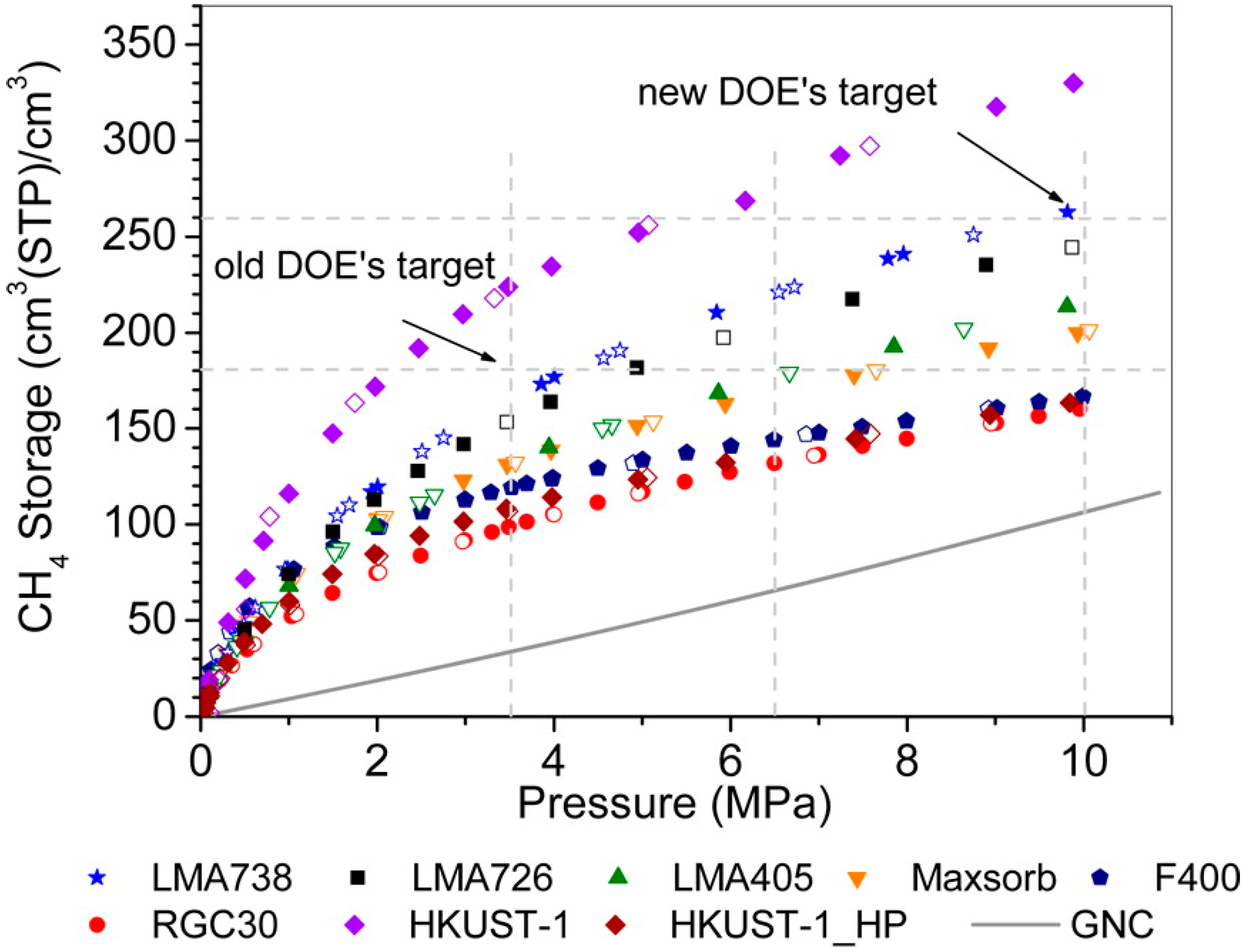
Figure 3.
(A) Model of pore surface consisting of a sphere of atoms, uniformly distributed. (B) Model with smeared atoms forming a spherical shell with radius R. (C) Hexagonally close-packed unit cell consisting of spherical pores. (D) Potential energy of CH4 as a function of distance from sphere wall for this model. (E) The simulated heat of adsorption (kJ/mol) of CH4 as a function of pore diameter. (F,G) Deliverable CH4 capacity as a function of pore diameter. Calculations were completed between 1 and 35 bar and 65 and 5 bar. Dashed line is the deliverable capacity of a free space tank assuming pressure equals fugacity, as assumed in this sphere model analysis. Adapted with permission from Ref. [65]. Copyright 2014 American Chemical Society.
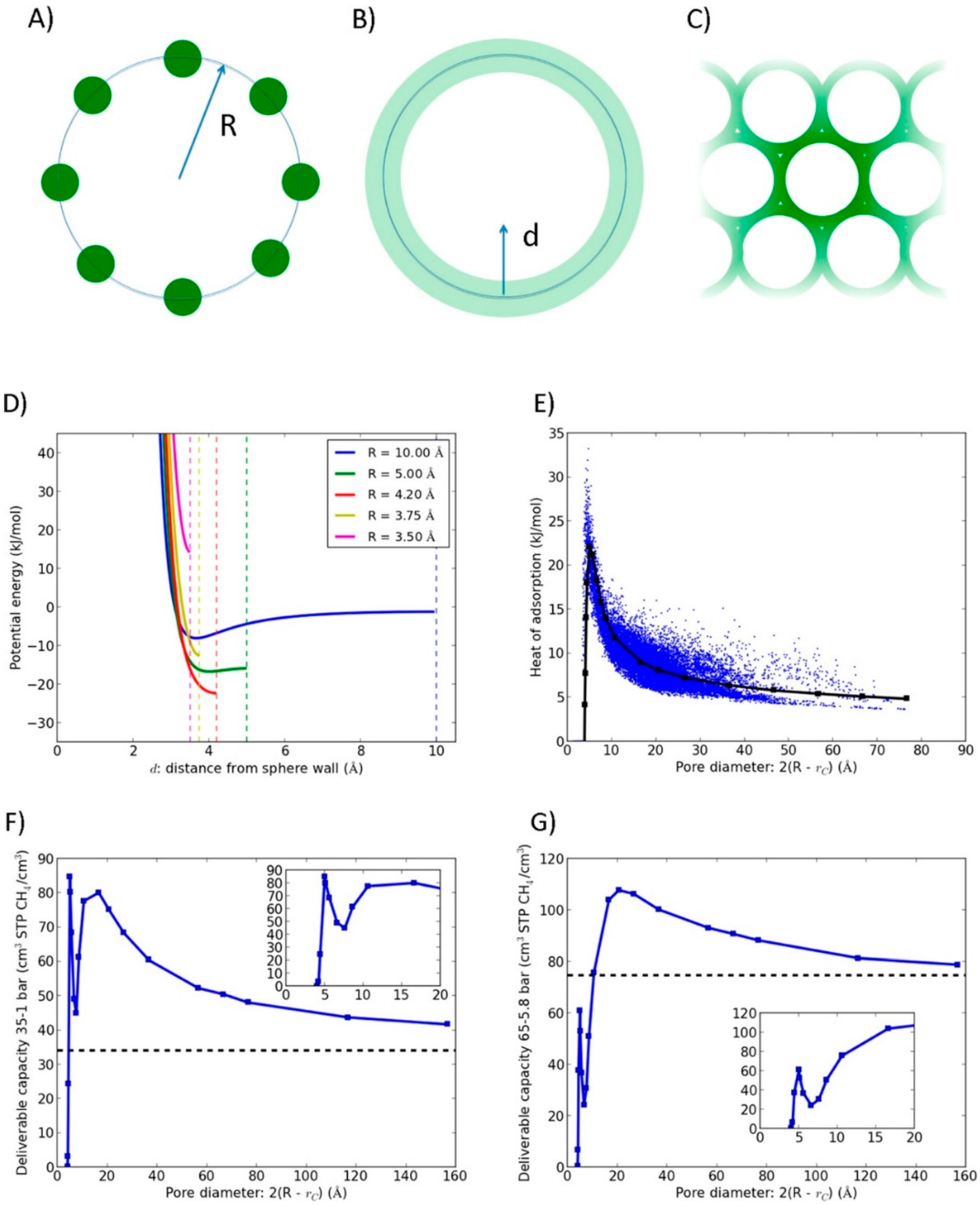
Figure 4.
(a) Carborane–bis(isophthalic acid) ligand (LH4); (b) NU-135, which is a MOF which has a p-carborane subunit and Cu metal sites. Adapted with permission from Ref. [107]. Copyright 2013 American Chemical Society.
Figure 4.
(a) Carborane–bis(isophthalic acid) ligand (LH4); (b) NU-135, which is a MOF which has a p-carborane subunit and Cu metal sites. Adapted with permission from Ref. [107]. Copyright 2013 American Chemical Society.

Figure 5.
Nanocages of NU-111, Ni-MOF-74, PCN-14, UTSA-20, HKUST-1, and NU-125 and their empirical formulas. Carbon atoms are shown in gray, hydrogen atoms are shown as black spheres, oxygen atoms are shown as red spheres, copper atoms are shown as cyan spheres, and nitrogen atoms are shown as blue spheres. Adapted with permission from Ref. [70]. Copyright 2013 American Chemical Society.
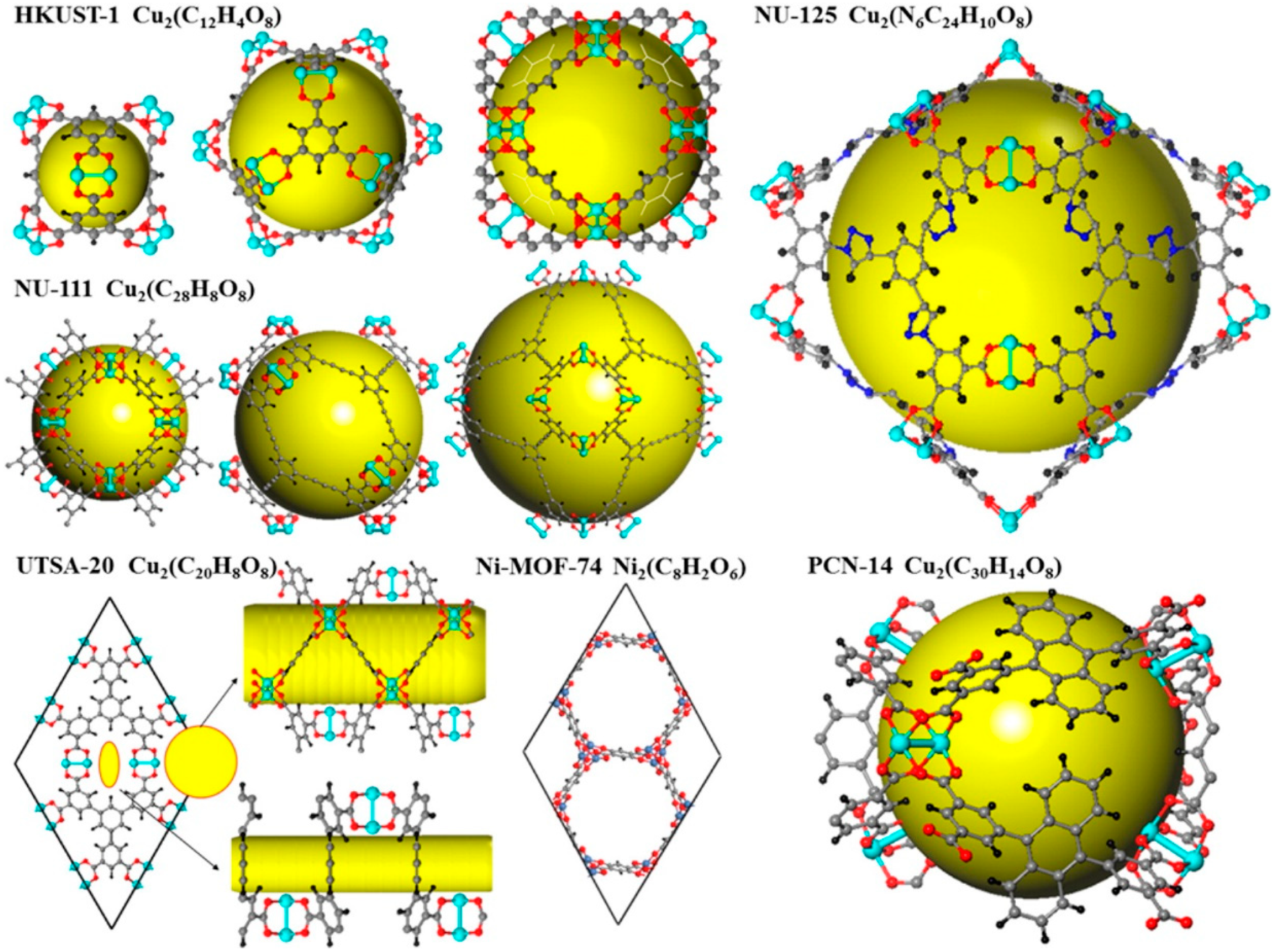
Figure 6.
(a) M2(dhtp) (dhtp = 2,5-dihydroxyterephthalate) crystal unit cell with adsorbed CH4 molecules on open metal site I. The location of sites was determined by neutron diffraction. (b) Metal oxide pyramids, organic linkers, and methane molecules. Adapted with permission from Ref. [136]. Copyright 2009 American Chemical Society.
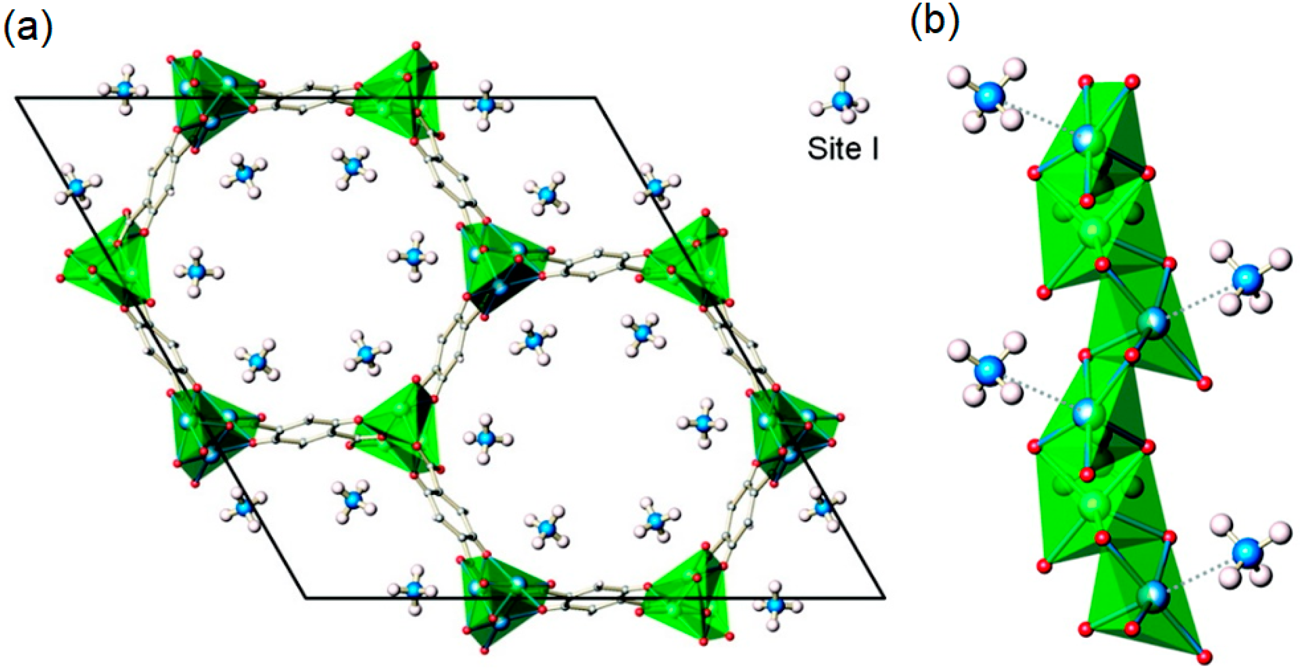
Figure 7.
(a,b) Organic and inorganic SBUs used to build the zyg net of UTSA-20. Carbon atoms are represented in black, oxygen atoms are represented in red, and copper atoms are represented in blue. Geometric shapes are made based on the underlying net to aid in the representation of the structure of this MOF. (c) Coordination figure of UTSA-20 which gives insights into how the secondary building units (SBUs) and geometric shapes are assembled to create this topology. Adapted with permission from Ref. [64]. Copyright 2011 John Wiley and Sons.
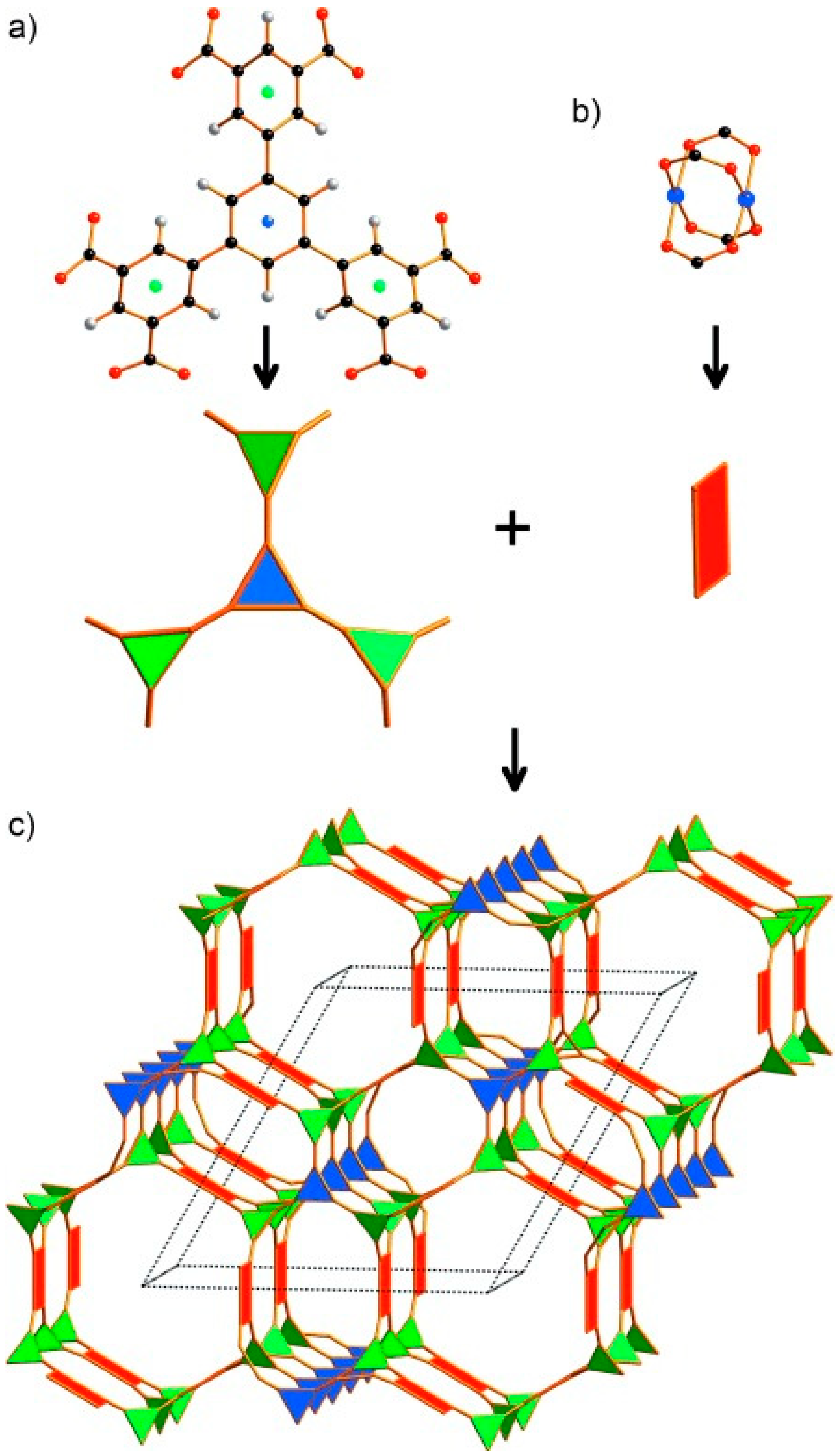
Figure 8.
Methane storage in flexible Co(bpd) from a pressure of 0 to 70 bar. (a) Collapsed and expanded Co(bpd) represented by a space-filling model. Atom color codes: carbon, grey; nitrogen, blue; cobalt, purple; and hydrogen, white. (b) Excess methane adsorption isotherms for Co(bpd) at 298 K at different applied external pressures at their corresponding densities. Adsorption-filled circle and desorption- open circles. Adapted with permission from Ref. [72]. Copyright 2015 Nature.

Figure 9.
(a) Isotherms for methane uptake on ST-2 MOFs at different temperatures and pressures between 5–200 bar. (b) Deliverable capacity of ST MOFs as compared to other MOFs, activated carbon, zeolites, and CNG between 5–200 bar. Reprinted with permission from Ref. [50]. Copyright 2017 American Chemical Society.


Table 1.
Pore volume, methane uptake, and methane deliverable capacity of selected metal-organic frameworks (MOFs).
Table 1.
Pore volume, methane uptake, and methane deliverable capacity of selected metal-organic frameworks (MOFs).
| MOF | VP (cm3 g−1) a | BET (m2 g−1) | Uptake b (cm3 cm−3) | Delivery c (cm3 cm−3) | T (K) | P (bar) | Qst (kJ mol−1) | Ref. |
|---|---|---|---|---|---|---|---|---|
| UTSA-110a | 1.263 | 3241 | 241 | 190 | 273.15 | 65 | 14.5 | [66] |
| HKUST-1 | 0.78 | 1850 | 267 | 183 | 298 | 65 | 17.0 | [67] |
| MFM-112a | 1.62 | 3800 | 236 | 200 | 298 | 80 | 16.2 | [68] |
| NU-1501-Al | - | 7310 | 262 | 238 | 270 | 100 | - | [61] |
| Al-soc-MOF-1 | 2.3 | 5585 | - | 264 | 258 | 80 | - | [69] |
| PCN-14 | 0.85 | 2170 | 230 | 154 | 298 | 65 | 17.6 | [70] |
| NJU-Bai 43 | 1.22 | 3090 | 254 | 198 | 298 | 65 | 14.45 | [49] |
| PCN-61 | 1.36 | 3000 | 219 | 174 | 298 | 65 | - | [71] |
| ST-2 | 2.67 | 5660 | - | 303 | 283 | 200 | - | [50] |
| ST-2 | 2.67 | 5660 | - | 289 | 298 | 200 | 9.2 | [50] |
| Co(bpd) | - | 2911 | - | 197 | 298 | 65 | 8.3 | [72] |
| NU-135 | 1.02 | 2530 | 230 | 170 | 298 | 65 | 16.6 | [73] |
| NU-125 | 1.29 | 3120 | 228 | 180 | 298 | 58 | 15.5 | [74] |
| ZJU-25 | 1.183 | 2124 | 229 | 181 | 300 | 63 | 15.1 | [75] |
| MOF-519 | 0.938 | 2400 | 355 | 306 | 298 | 250 | 14.6 | [76] |
| MOF-5 | 1.4 | - | 214 | 182 | 298 | 65 | 12.3 | [13] |
| NJU-Bai 19 | 1.063 | 2803 | 246 | 185 | 298 | 65 | 14.8 | [77] |
| Cu-tbo-MOF 5 | 0.595 | 3971 | 216 | 175 | 298 | 80 | 20.4 | [78] |
| MIL-53(Al)–NH2 | 0.50 | 947 | 123 | 119 | 298 | 65 | - | [79] |
| MOF-905 | 1.34 | 3490 | 207 | 175 | 298 | 65 | 11.7 | [12] |
a Vp: pore volume. b Total volumetric uptake, cm3 (STP) cm−3. c The deliverable amount is defined as the difference in total uptake between 5 bar and the specified upper limiting working pressure under isothermal conditions.
Table 2.
Pore volume, methane uptake, and methane deliverable capacity of selected porous organic polymers [4].
Table 2.
Pore volume, methane uptake, and methane deliverable capacity of selected porous organic polymers [4].
| Compound | VP (cm3 g−1) a | BET (m2 g−1) | Uptake b (cm3 cm−3) | Uptake (g g−1) | T (K) | P (bar) | Qst (kJ mol−1) | Ref. |
|---|---|---|---|---|---|---|---|---|
| COF | ||||||||
| COF-1 | 0.38 | 1230 | - | 0.109 | 298 | 100 | 24.9 | [80] |
| COF-5 | 1.17 | 1520 | - | 0.169 | 298 | 100 | 12.5 | [80] |
| COF-6 | 0.32 | 750 | - | 0.062 | 298 | 35 | 19 | [81] |
| COF-8 | 0.69 | 1350 | - | 0.08 | 298 | 35 | 12 | [81] |
| COF-10 | 1.44 | 1760 | - | 0.074 | 298 | 35 | 8.5 | [81] |
| COF-102 | 1.81 | 4940 | 255 | 0.284 | 298 | 100 | 9.6 | [80] |
| COF-103 | 2.05 | 5230 | 260 | 0.31 | 298 | 100 | 9.8 | [80] |
| COF-105 | 4.94 | 6450 | - | 0.405 | 298 | 100 | 8.5 | [80] |
| COF-108 | 5.40 | 6280 | - | 0.415 | 298 | 100 | 8.5 | [80] |
| HCPs | ||||||||
| HCP-1 | 0.54 | 1904 | - | 0.077 | 298 | 20 | - | [82] |
| HCP-2 | 0.36 | 1307 | - | 0.067 | 298 | 20 | - | [82] |
| HCP-3 | 0.32 | 963 | - | 0.049 | 298 | 20 | - | [82] |
| HCP-4 | 0.55 | 1366 | - | 0.065 | 298 | 20 | 20.8 | [82] |
| PPNs | ||||||||
| PPN-1 | 1249 | 0.45 | - | 0.076 | 295 | 35 | 18.1 | [83] |
| PPN-2 | 1764 | 1.26 | - | 0.098 | 295 | 35 | 16.4 | [83] |
| PPN-3 | 2840 | 1.7 | - | 0.122 | 295 | 35 | 15.2 | [83] |
| PPN-4 | 6461 | 3.04 | - | 0.389 | 295 | 55 | - | [83] |
a Vp: pore volume. b Total volumetric uptake, cm3 (STP) cm−3.
Table 3.
Pore volume, methane uptake, and methane deliverable capacity of selected carbon materials.
Table 3.
Pore volume, methane uptake, and methane deliverable capacity of selected carbon materials.
| Carbon | VP (cm3 g−1) a | BET (m2 g−1) | Uptake b (cm3 cm−3) | Uptake (g g−1) | T (K) | P (bar) | Ref. |
|---|---|---|---|---|---|---|---|
| Kansai Maxsorb | 0.93 | 2671 | 127 | 0.26421 | 298 | 35 | [84] |
| NUCHAR-RGC | 1.1 | 1600 | 120.3 | 0.15117 | 299 | 35 | [85] |
| Darco® AC | 0.131 | 651.69 | 145.5 | 0.11302 | 298 | 35 | [86] |
| SMS-30 | 0.98 | 2860 | 120 | 0.21964 | 298 | 35 | [86] |
| SMS-22 | 0.84 | 2451 | 150 | 0.16996 | 298 | 35 | [86] |
| SMS-19 | 0.88 | 2552 | 149 | 0.16363 | 298 | 35 | [87] |
| HSAC-21 | 0.83 | 1466 | 147.2 | 0.16166 | 296 | 35 | [85] |
| HSAC-23 | 0.58 | 1784 | 146.4 | 0.16078 | 300 | 35 | [85] |
| C1050P | 0.4 | 932 | 127 | 0.09251 | 298 | 35 | [88] |
| LMA738 | - | - | 276 | - | 298 | 200 | [89] |
| MAXSORB III | 0.179 | 3140 | 60 | 0.40758 | 300 | 35 | [90] |
| Activated Carbon | - | 3052 | - | 0.32 | 298 | 35 | [91] |
a Vp: pore volume. b Total volumetric uptake, cm3 (STP) cm−3.
© 2020 by the author. Licensee MDPI, Basel, Switzerland. This article is an open access article distributed under the terms and conditions of the Creative Commons Attribution (CC BY) license (http://creativecommons.org/licenses/by/4.0/).
Share and Cite
MDPI and ACS Style
Mahmoud, E. Evolution of the Design of CH4 Adsorbents. Surfaces 2020, 3, 433-466. https://doi.org/10.3390/surfaces3030032
AMA Style
Mahmoud E. Evolution of the Design of CH4 Adsorbents. Surfaces. 2020; 3(3):433-466. https://doi.org/10.3390/surfaces3030032
Chicago/Turabian StyleMahmoud, Eyas. 2020. "Evolution of the Design of CH4 Adsorbents" Surfaces 3, no. 3: 433-466. https://doi.org/10.3390/surfaces3030032