
Molecular Dynamics Modeling of Mechanical Properties of Polymer Nanocomposites Reinforced by C7N6 Nanosheet


1
Institute of Continuum Mechanics, Leibniz Universität Hannover, An der Universität 1, 30823 Garbsen, Germany
2
Computational Science and Simulation Technology, Leibniz Universität Hannover, Appelstraße 11, 30167 Hannover, Germany
*
Author to whom correspondence should be addressed.
Surfaces 2021, 4(3), 240-254; https://doi.org/10.3390/surfaces4030019
Submission received: 30 July 2021
/
Revised: 18 August 2021
/
Accepted: 20 August 2021
/
Published: 24 August 2021
(This article belongs to the Special Issue Interfaces in Materials Science and Engineering)
Abstract
:Carbon-nitride nanosheets have attracted remarkable attention in recent years due to their outstanding physical properties. is one of the hotspot nanosheets which possesses excellent mechanical, electrical, and optical properties. In this study, the coupled thermo-mechanical properties of the single nanosheet are systematically investigated. Although temperature effects have a strong influence on the mechanical properties of monolayer, thermal effects were not fully analyzed for carbon-nitride nanosheet and still an open topic. To this end, the presented contribution aims to highlight this important aspect and investigate the temperature influence on the mechanical stress-strain response. By using molecular dynamics (MD) simulation, we have found out that the monolayer’s maximum strength decreases as the temperature increase from 300 K to 1100 K. In the current contribution, 5% to 15% volume fractions of /P3HT composite were employed to investigate the reinforcing ability. Significantly, the uniaxial tensile of composite reveals that can enhance the maximum strength of the composite to 121.80 MPa which is 23.51% higher than the pure matrix. Moreover, to better understand the enhanced mechanism, we proposed a cohesive model to investigate the interface strength between the nanosheet and P3HT matrix. This systematic study provides not only a sufficient method to understand the thermo-mechanical properties, but also the reinforce mechanism of the reinforced nanocomposite. Thus, this work provides a valuable method for the later investigation of the nanosheet.
1. Introduction
Nowadays, two-dimensional (2D) materials [1,2,3] are among the most attractive research topics due to their excellent physical properties in comparison with conventional materials. Graphene (GN) is a typical 2D material that has high electrical [4], thermal conductivity [5,6], and mechanical [7] properties. GN has the simplest lattice structure while compared with other two dimensional materials like , , and . However, one of the shortages for GN is the thermo-mechanical stability. The stability of GN can reach only 480 C as reported in [8]. This limits the wide application of GN in some field. Apart from the Graphene monolayer, the carbon-nitride family monolayer has attracted wide attention from researchers in recent years due to the diverse lattice structures and their excellent electrical, and optical properties. Different from Graphene, graphitic carbon nitrides exhibit porous atomic lattices and low thermal conductivities [9]. Among the various classes of 2D materials, carbon-nitride nanomembranes have been among the most successful nanomaterials that have inherent semiconducting electronic characters [10]. The carbon-nitride compounds consisting of covalent-bond grids of carbon and nitrogen atoms are the most successful, which possess lower thermal conductivities than graphite and exhibit semiconducting properties [11]. Carbon-nitride nanomaterials exhibit a stiff and stable physical component owing to the formation of strong covalent bonds between the C-C and C-N bonds [10]. In this regard, the maximum strength of carbon-nitrides depends much on the strong covalent bonds (C-C, C-N). Previous works have found that monolayer exhibits a strong elastic tensile modulus of 212 N/m, as outlined in [10].
In the last decade, an investigation reveals that carbon-nitride as a novel semiconductor has excellent mechanical properties and tensile strength can reach GPa.nm [12] which is very close to defect-free Graphene. In terms of energy storage and conversion, displays a much smaller voltage hysteresis than graphene; this also indicates its promise as a new anode material for lithium-ion batteries [13]. With the consideration of the excellent mechanical properties, various graphitic carbon-nitrides are used in energy conversion/storage, catalysis [14], photocatalysis [15], and oxygen reduction systems [16,17,18]. From the perspective of stability, the can be stable up to 550 C in air, which is more stable than GN with stability only up to 480 C [8]. Among several carbon-nitride monolayers, was founded to be a new 2D structure composed of -hybridized carbon atoms forming hexagonal lattice [11]. An investigation from Wu et al. [11] have successfully found out that the has high-temperature stability by Ab initio molecular dynamics simulations(AIMD) which indicates mechanical stability and maintains stability at high temperatures up to 1500 K for monolayer. The AIMD simulations were conducted at 300, 500, and 1000 K for 20 ps long simulations which reveals that the nanosheet can stay completely intact at all the studied temperatures [10]. Moreover, by solving the full Boltzmann transport equation, monolayer was found to possesses good electronic transport properties and high lattice thermal conductivities (134.55 W/mK at 300 K) [11]. has strong stability and stiff mechanical response owing to the covalent bond interaction from C-C and C-N bonds, as concluded in [9,10].
Current development in carbon-nitride fabrication technologies has also accelerated the exploration of nanomaterials with the combined theoretical investigation. A recent study by Hu et al. [19] shows that monolayer demonstrates the high capacity and efficient reversibility for hydrogen storage in a realistic condition. However, to the best knowledge of the authors, the temperature influence for the monolayer in the field of a mechanical response and the combined interface strength of with polymer matrix is an open topic. As well documented the P3HT is a semiconductor polymer which has good conductivity, electric property, and conversion efficiency [20,21,22]. However, the mechanical property of P3HT is not comparable to conventional polymer, since the fracture of material takes place at the strain % [23] of the mechanical loading. On the other hand, P3OT and P3DDT are from the same polymer family with a strain of %, % for a crack in tensile loading, respectively [24]. Hence, to increase the mechanical properties, many researchers intend to use conductive or mechanical reinforced particles dispersed in an elastic matrix as outlined in [25]. On behalf of the strong thermal stability and mechanical properties, will be used as a reinforcement to enhance the P3HT polymer.
Hereby, demonstrates good temperature stability, but how does this temperature influence the fundamental stress-strain relationship is still unknown. Furthermore, how strong the interface strength between and matrix is unclear yet. Those issues limit the further application and development of in the field of the electrical and aerospace industry and fabrication. To address these issues, we systematically investigate firstly the mechanical properties of the monolayer and the temperature influence for the stress-strain response. Secondly, a nanocomposite of with different volume fractions of will be analyzed to investigate their mechanical properties as well as the enhancement of semiconductor P3HT polymer. Finally, a cohesive model is carried out to predict a non-bond interaction (normal interface strength).
2. Simulation Methodology
The structure of the monolayer consists of 3640 atoms having a width of Å and height of Å as documented by VESTA [26] and sketched in Figure 1a. For better understanding, Figure 1b represents the single lattice structure of the monolayer; every single lattice has 7 carbon atoms and 6 nitrogen atoms, where the brown atoms represent carbon atoms; the gray atoms represent nitrogen atoms. The basic load direction for the monolayer in the X-direction along the edge during the uniaxial tensile test is demonstrated in Figure 1c. It is worthwhile to mention that the thickness of the monolayer cannot be neglected. To this end, a thickness of Å is used to define the thickness along the Cartesian direction, see [12].
During the uniaxial tensile test of the monolayer, the structure atoms number should be big enough to overcome the fluctuation which will influence the final results. For more details about the specific structure data of the lattice, the atomic structure with VASP POSCAR format is provided in Appendix A.
2.1. Potential and Uniaxial Tensile for Monolayer
In this contribution, the optimized tersoff potential was proposed by Lindsay and Broido for the formulation of the interactions of the carbon-carbon atoms [27]. The potential parameters for the carbon-nitrogen interactions were adopted from the research by Klnacl [28]. The accuracy of the predictions derived from the MD simulations strongly correlates to the appropriate selection of the potential to define the atomic interactions [12], since the potential plays a key role in the accuracy calculation during the simulation. The optimized tersoff potential is the most accurate potential for molecular dynamics simulation of the mechanical and thermal transport along with carbon structure [29]. Therefore, the BNC.tersoff potential file was chosen for monolayer tensile. Hereby, Tersoff parameters for B, C, and BN-C hybrid-based graphene-like nanostructures can be found from BNC.tersoff [30]. To this end, the N-N, N-C, and C-C bond parameters are used. For more detail about the potential, please see Appendix B.
As a result of the porous structure of , the uniaxial tensile test is carried out along X (Cartesian a) and Y (Cartesian b) directions to check the anisotropic mechanical response. In this study, a molecular dynamics method was carried in the simulation by LAMMPS (Large-scale Atomic/Molecular Massively Parallel Simulator) open-source package [31]. A periodic boundary condition was defined along X, and Y-direction; however, a non-periodic and shrink-wrapped boundary was defined in Z-direction. To avoid any sudden bond stretching or void formation due to the loading conditions, the atomic positions at every step of the loading were rescaled according to the applied changes in the simulation box size [12]. Moreover, the time increment and pair style were defined as femtoseconds (fs) and tersoff respectively under the metal unit system. Next, a Gaussian distribution initial velocity was used to initialize the structure before the simulation. Then a cooling procedure was carried out for the structure from 500 K to 300 K by Nose Hoover barostat and thermostat (, see [32]) method for 30 picoseconds (ps). Besides, an equilibrium process should be taken for the structure within the target temperature (300 K) for 30 ps in an ensemble. Next, several constant strain rates ( s, s, s, and s) are carried out during the uniaxial test in ensemble. Every 1000 fs, the virial stress [33] was averaged 2 times to print the engineering stress-strain response. To fully understand the temperature influence for the stability of , we also test a monolayer at different temperatures (300 to 1100 K) within the control of the ensemble. Those temperature comparisons are also carried out in a Y-direction within a constant strain rate of s. Apart from this, other steps are the same as mentioned above.
2.2. Nanocomposite Mechanical Test
In the second part of this work, the mechanical properties of the reinforced nanocomposite are further analyzed. To this end, a specifically designed volume fraction composite structure is built by Materials Studio (MS). Herein, three types of volume fractions (, , ) of are randomly inserted within a size of Å () cubic. Those models are depicted in Section 3.3. Then the contained coordinates and force field parameters files are transferred into LAMMPS in Linux system to generate the data file before the simulation. During the uniaxial tensile test of the nanocomposite, a periodic boundary condition was defined for the structure along with three Cartesian directions within a unit of real unit system [34], for more detail of the unit sees LAMMPS manual. Furthermore, the simulation accuracy was predefined as within Ewald [35]. A hybrid pair style was used to describe the atoms pairs since the polymer matrix and the monolayer were described by Lennard-Jones 6-9 potential with a cutoff of Å and tersoff potential, respectively. Another bond, angle, dihedral, and improper style was defined as class2 (second generation force field [36]). To better understand the mechanical response of nanocomposite, a small-time increment of femtoseconds (fs) is used. Then an initial equilibrium stage will be carried out by with 500 K for 50 picoseconds. After the nanocomposite is fully equilibrated, the system is cooling down from 500 K to a target temperature of 300 K for 50 picoseconds by ensemble. Thereafter, we equilibrate the structure at 300 K for 80 ps to guarantee its full relaxation at this target temperature of 300 K. Next, we start applying the load from the initial state during the uniaxial tensile test. Then, the structure will be stretched along X-direction under an [37] ensemble to control the temperature at 300 K for 2000 ps. Every 2 ps, the mechanical response will be printed 1 time to output the fundamental stress and strain data.
2.3. Cohesive Model for — Interface Investigation
In this section, a cohesive model is built to investigate the non-bond interaction between monolayer and polymatrix. In this regard, we have proposed an analytical model and combined molecular dynamics (MD) simulation with the analytical model of [38] to investigate the normal strength between the monolayer and polymer matrix. For molecular dynamics (MD) result, the non-bond interaction can be formulated by Lennard-Jones 6-9 potential P
as proposed in [39], where r describes the current distance, represents equilibrium energy depth and depicts the equilibrium distance between two atoms formulated by i and j without bond connection. Following [40], and can be defined as
, are i and jth type atoms-distance and energy. In the presented contribution, several specific model parameters were listed in Table 1 which was generated by the PCFF [39] force field in the toolbox of LAMMPS.
By defining the distance between monolayer and polymer matrix with the parameter h, we introduce the cohesive energy per unit area as
in terms of the n types of atoms in the polymer unit, here we have 4 types (see Table 1). is the area density m which represents the number of atoms per unit area of . This can be evaluated based on our structure with given height and width as plotted in Figure 1a. is the volume density (number of polymer molecules per unit volume) of the i-th type of polymer atoms. Mass density of was tested kg/m ( g/cm [41,42]). Mass of every unit () was evaluated at kg. Then can be evaluated by dividing of the mass density with respect to the mass of the unit polymer. Therefore, m, see [43]. For different types of atoms in Table 1, the is equal to multiply by mole ratio. Hence, cohesive stress can be defined as
By taking the necessary derivation and reformulations we end up with the following compact form
herein A represents atoms. Next, we replace the distance , where is the equilibrium distance at and d represents the separated distance, thus the cohesive stress yields
The key goal here is to employ the cohesive model (presented above) at the interface between and and compare it with the proposed molecular dynamics MD simulations. The basic structure can be presented in Section 3.4. The model was constructed with a size of Å () and 23,790 atoms. In this section, a non-equilibrium molecular dynamics(NEMD) was carried out to predict the interfacial strength. Firstly, a non-periodic boundary condition with a shrink-wrapped boundary was defined in Z-direction since a normal velocity of Å/ps was loaded in Z-direction. Other Cartesian axes () were also defined as periodic boundary conditions. Furthermore, the top monolayer will be separated within 10 nm and the time increment is defined as 0.2 fs. The bottom part, which is below 20 Å along Z-direction, is fixed in all directions to get the interfacial strength. The pair, angle, dihedral, and improper style are the same as the previous definition in Section 2.2. During the separation process, the system is fixed at a target temperature of 300 K within the control of the ensemble.
3. Results and Discussion
3.1. Mechanical Properties and Thermal Stability Test
The material fracture depends on many working conditions. The material strength under different temperatures indicates the stretchability for thermal resistance and stability. To better understand the temperature influence for the target carbon-nitride monolayer, we have tested the mechanical response of at different temperatures (300 to 1100 K). Such a temperature domain is reliable as confirmed in [11] resulting in good mechanical stability (stable to 1500 K) and maintains the stability of by using Ab initio molecular dynamics simulations (AIMD). Here, we take the temperature into consideration, since we want to investigate the temperature’s influence on the mechanical response of a single monolayer. The fundamental stress-strain curve of for different temperatures is shown in Figure 2. It can be observed that the uniaxial tensile strength of gets decreasing with the increase of temperature from 300 K to 1100 K while loading in both X and Y-direction. The mechanical response of Y-direction illustrates more ductile failure behavior as shown in Figure 2b, while the stress-strain response in X-direction exhibits an earlier failure before yielding, see Figure 2a. Furthermore, it is worthwhile to mention that monolayer possesses high-temperature stability. From the stability perspective of carbon-nitride, the can be stable up to 550 C (823.15 K) in air, which is more stable than with stability only up to 480 C (753.15 K) [8]. Interestingly, comparing with , our investigation finds out that the can be stable up to 1100 K in both directions (X, and Y). This conclusion confirmed the previous report from Wu et al. [11] that the mechanical stability of monolayer can reach high-temperature (maximum 1500 K). The maximum strength of for X and Y-direction are , GPa.nm, respectively, under 1100 K (see Table 2), and the corresponding strains are and , respectively. For the evaluation of the true stress or strength of monolayer, the depicted results are supposed to be divided by the monolayer thickness ( Å) as documented in [12].
In order to evaluate anisotropicity in the mechanical properties, uniaxial tensile simulations were conducted along with the two perpendicular planar directions, see Figure 3b. With the point of the vesicular texture of two dimensional from Figure 1b, the result from Figure 3b indicates that produces isotropic mechanical response along with X, and Y-direction. The initial linear stress-strain relations from Figure 3b coincide closely with the loading along with X, and Y-directions, which reveals convincingly isotropic elasticity for the modulus. The isotropic or anisotropic elasticity modulus of the nanosheet is base on the modulus comparing armchair and zigzag orientation. When the modulus of the armchair and zigzag is the same, then the nanosheet can be regarded as isotropic elasticity. This formulation can be traced back to an explanation from the previous work at here [44]. However, comparing the maximum tensile strength along X, and Y-direction of monolayer, the result shows an anisotropic response, the difference strength can reach 1.81 GPa.nm.
Based on the mechanical response of at Figure 3a,b, we can conclude that can be used as a sensor material since has not just only strong temperature stability but also very fine linear mechanical response during the uniaxial tensile. Comparing the previous tested stress-strain curve of typical two-dimensional materials, e.g., Graphene [44], [12], and [44] monolayer, we can conclude that the monolayer with many porosities shows obviously elastic modulus since the monolayer has a very fine linear mechanical response before the fracture of structure.
Next, different strain rates ( s to s) in Figure 3a are investigated to further study its influence on the mechanical properties of . The strength of the monolayer gets increases as the strain rates increase. Hereby, the stress drops dramatically after reaching maximum strength. The maximum strength of was tested at GPa.nm at the strain rate of s and 300 K during the uniaxial tensile test, this strength is a little bit different from previous density functional theory (DFT) calculations of GPa.nm [10] by Vienna Ab initio Simulation Package (VASP) [45,46,47]. On the one hand, a larger time increment choosing might be a reason for the difference. Furthermore, classical molecular dynamics (CMD) simulations offer the possibility to study larger systems at elevated temperatures, but CMD requires accurate interatomic potentials to formulate the C-N, and C-C bond for carbon-nitride. In our study, the C-N bond and C-C bond are likely to be in line with the loading direction during the tensile of the monolayer (Figure 1a). In other words, those two types of bonds bear the load parallel together. However, the maximum strength of has no much sensitivity for different strain rates, since most maximum strength is around 18–20 GPa.nm at the strain around 0.15. This also represents that has not just only a stable property at high temperature but also a stable tensile strength with different strain rates.
3.2. Fracture Analysis
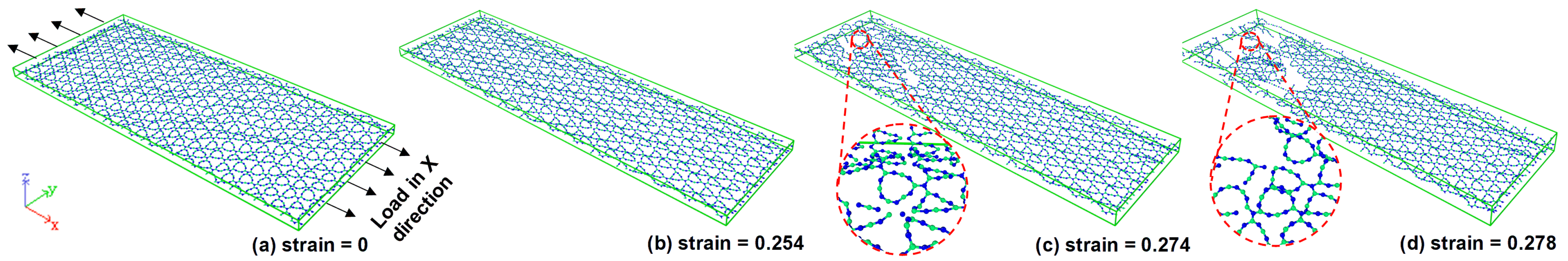
During the monolayer fracture deformation analysis, it can be found that the first debond of is the C-C bond at the strain of 0.268 during the uniaxial tensile test along with the X-direction at 300 K. However, an obvious crack shape of took place at the strain of 0.274; this can be depicted in Figure 4. After the crack point, the crack extends rapidly to the edge within a short strain of 0.004.
From Figure 4 and Figure 5, we can find that the fracture resistance ability along the Y-direction is weaker compared with loading in the X-direction. Since the first fracture takes place at the shorter strain of 0.165; however, a fracture appearing along the X orientation is at the strain of 0.274. This result reveals that the monolayer has a stronger loading resistance in the X-direction. Figure 5 reveals that the crack takes place first in the bottom edge of the monolayer. Then, a new crack takes place in the right bottom edge of the structure. It can be seen from Figure 5c,d that the crack extends from the left and right sides to the middle side along the top edge. For the same initial crack of the sheet materials, the stress intensity defector of the edge is much bigger than the internal crack for the fundamental plane stress case. Therefore, the fracture will happen much possible on the edge. That is the reason why the tensile crack extends from the edge to the middle as shown in Figure 4 and Figure 5 fracture propagation. Moreover, the crack of extends in a crook path instead of the straight line like as outlined in [48]. This represents that the mechanical property of is not fully brittle as the stress-strain result shown in Figure 3. During the analysis of the ruptured sample along with those two orientations, we confirmed that the first debonding of the investigated monolayer in this study taking place at the C-C bond. This means that the maximum tensile strength of relies much on the maximum bond strength of the C-C bond no matter how in X, and Y-directions.
3.3. Composite Deformation
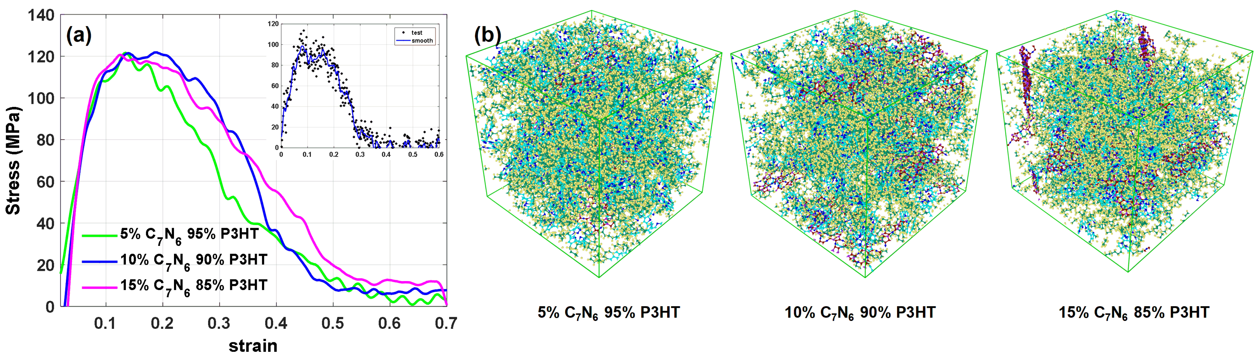
Next, we show the benefit of employing within a nanocomposite of in this benchmark test. The fundamental stress-strain curves of the with different volume fractions are presented in Figure 6a. Those curves are the outcome of a Gaussian smooth algorithm (SMOOTHDATA) from MATLAB to reduce the noise from the data. Among several volume fraction strength comparisons, we find out that the as reinforcement can not only enhance the maximum strength for the composite but also make the pure matrix more ductile.
Hereby, the strength of only pure matrix reaches zero when stretched at a strain of 0.3. However, the strain increase to around 0.6 for enhanced nanocomposite, as shown in Figure 6a. Worthy to mention that can enhance the strength of the matrix to around 120 MPa. The maximum tensile strength (121.80 MPa) of the composite can be gotten with ; this composite can keep a maximum strength from a strain of 0.1 to 0.2 during the tensile. Comparing with the maximum tensile strength of pure with 98.61 MPa after smoothing, can enhance the maximum tensile strength of the composite to .
3.4. Interfacial Mechanical Properties
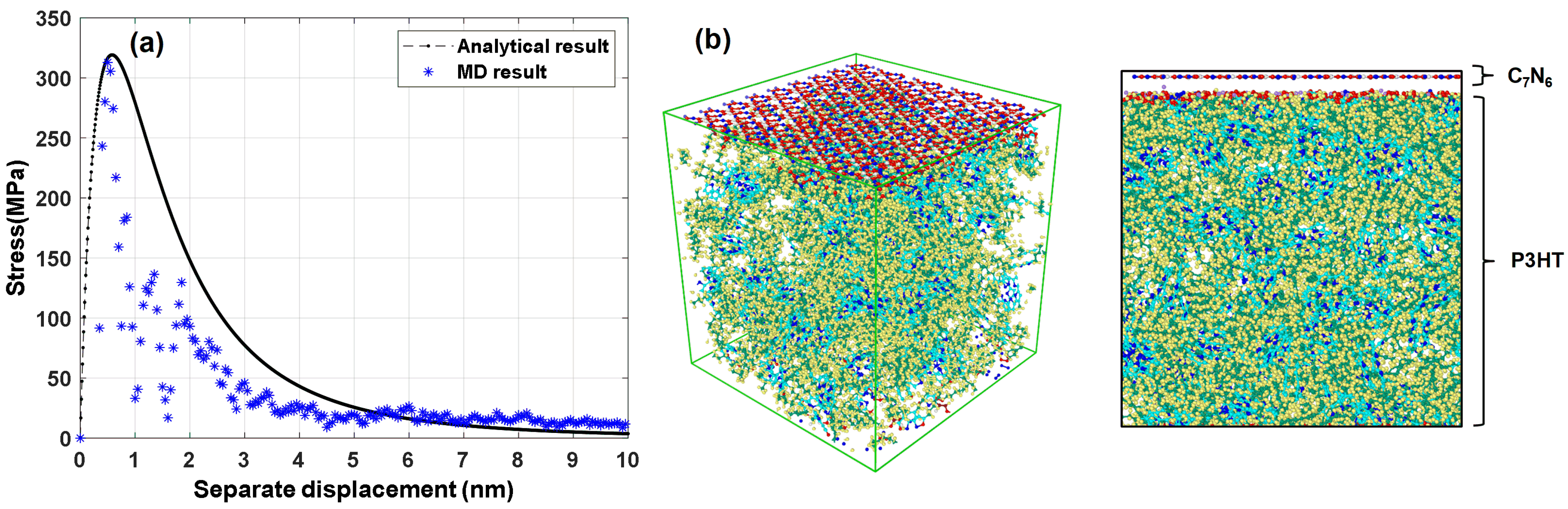
For further investigation of the proposed combination of composite, we carried out a 10 nm separated distance from the polymer. Here a comparison between the theoretical cohesive model and the proposed model with classic molecular dynamics is carried out in Figure 7a. The maximum traction stress for the MD simulation result was evaluated at 248.86 MPa. The difference between MD and analytical traction results (236.95 MPa) is 11.91 MPa which is closed to the analytical result. However, the normal strength of separated from the matrix is larger than the maximum strength of pure . In other words, a stronger non-bond strength was constructed at the interfacial part. This can enhance strength for the nanocomposite. A crack will take place at the weakest part of the structure. Based on our finds, we can assume that the crack will not happen initially in the monolayer and matrix interface region since a stronger strength is constructed by the Van der Waals interaction.
4. Conclusions
In this study, we systematically investigated the thermo-mechanical properties of the monolayer. We found out that monolayer has strong stability at a high temperature(1100 K). By loading the structure in X and Y-directions, the isotropic behavior was confirmed at a constant strain rate of s. The uniaxial tensile test of composite reveals that can enhance the maximum strength of the composite to 121.80 MPa which is higher than the pure matrix strength. Finally, a cohesive model was carried out to predict the non-bond interaction between monolayer and P3HT polymer matrix. As an outcome of this construction, a stronger non-bond strength was achieved at the interface. This failure model will be extended towards the phase-field approach to fracture in line with [49,50,51] in the future analysis.
Furthermore, it should be noticed that the reinforcing mechanism of the reinforced nanocomposite is complicated. The interface strength is only one of the important parts for the enhancement of the /P3HT composite. Our result has found that the monolayer can enhance the mechanical property of /P3HT by strong interface strength. Other reinforcing factors need to be further investigated in future work.
Author Contributions
Conceptualization, F.A. and B.M.; methodology, F.A. and B.M.; software, Q.Z.; validation, Q.Z., F.A. and B.M.; formal analysis, F.A.; investigation, F.A. and B.M.; resources, F.A.; data curation, Q.Z.; writing—original draft preparation, F.A. and Q.Z.; writing—review and editing, F.A. and Q.Z. and B.M.; visualization, F.A. and Q.Z.; supervision, F.A. and B.M.; project administration, F.A.; funding acquisition, F.A. and B.M. All authors have read and agreed to the published version of the manuscript.
Funding
This research was funded by the German Research Foundation (DFG) within the collaborative research center (CRC 1153, Project ID 252662854) and Germany’s Excellence Strategy within the Cluster of Excellence PhoenixD (EXC 2122, Project ID 390833453).
Acknowledgments
F.A. and B.M. acknowledge the support of the cluster system team at the Leibniz Universität of Hannover, Germany in the production of this work. The authors also would like to thank Bo Yang for the fruitful discussions at the initial phase of this work.
Conflicts of Interest
The authors declare no conflict of interest.
Appendix A. Atomic Structures in VASP POSCAR Format
This appendix data contains all the coordinates and lattice parameters for building a single lattice of monolayer. By inputting all the data into VESTA, a single lattice structure of will be generated.
C7N6
1.00000000000000
6.7943948564804693 0.0000000000000000 0.0000000000000000
3.3971974282402351 5.8841185491832784 0.0000000000000000
0.0000000000000000 0.0000000000000000 15.0000000000000000
C N
7 6
Direct
0.9998100576047193 0.0002509396813224 0.5000000000000000
0.9331640163519950 0.7159702217766863 0.5000000000000000
0.9331204068991781 0.3511955830278453 0.5000000000000000
0.7155979589857679 0.9335029314294445 0.5000000000000000
0.7155586812735208 0.3512017827147176 0.5000000000000000
0.3507638336030467 0.9335002995972488 0.5000000000000000
0.3507380370779813 0.7159747027046279 0.5000000000000000
0.1110737155275103 0.1115015469972604 0.5000000000000000
0.1110716970172021 0.7777302000807538 0.5000000000000000
0.9928516147958462 0.5037223459642206 0.5000000000000000
0.7772919263856721 0.1115054214509428 0.5000000000000000
0.5034145543584359 0.9930456207717029~0.5000000000000000
Appendix B. Tersoff Potential to Simulate Mechanical Properties of C 7 N 6
This appendix contains all the parameters for the description of the bond interaction of monolayer. A BNC.tersoff potential can be generated by copying this into an empty file and append it into LAMMPS input file.
# DATE: 2013-03-21 CONTRIBUTOR: Cem Sevik CITATION: Kinaci, Haskins, Sevik and Cagin, Phys Rev B, 86, 115410 (2012)
# Tersoff parameters for B, C, and~BN-C hybrid based graphene like nano structures
# multiple entries can be added to this file, LAMMPS reads the ones it~needs
# these entries are in LAMMPS "metal" units:
# A,B = eV; lambda1,lambda2,lambda3 = 1/Angstroms; R,D = Angstroms
# other quantities are~unitless
# Cem Sevik (csevik at anadolu.edu.tr) takes full blame for this
# file. It specifies B-N, B-C, and~N-C interaction parameters
# generated and published by the reseacrh group of Prof. Tahir~Cagin.
# 1. Physical Review B 84, 085409 2011
# Characterization of thermal transport in low-dimensional boron nitride nanostructures,
#
# 2. Physical Review B 86, 075403 2012
# Influence of disorder on thermal transport properties of boron nitride nanostructures
#
# 3. Physical Review B 86, 075403 2012, Please see for further information about B-C and N-C parameters
# Thermal conductivity of BN-C nanostructures
#
# The file also specifies C-C, interaction parameters
# generated and published by the reseacrh group of Dr. D. A. Broido
# Physical Review B 81, 205441 2010
# Optimized Tersoff and Brenner empirical potential parameters for
# lattice dynamics and phonon thermal transport in carbon nanotubes and~graphene
# Users in referring the full parameters can cite the full parameter paper (3) as:
# A. Kinaci, J. B. Haskins, C. Sevik, T. Cagin, Physical Review B 86, 115410 (2012)
# Thermal conductivity of BN-C nanostructures
#
# format of a single entry (one or more lines):
# element 1, element 2, element 3,
# m, gamma, lambda3, c, d, costheta0, n, beta, lambda2, B, R, D, lambda1, A

References
- Mortazavi, B. Ultrahigh thermal conductivity and strength in direct-gap semiconducting graphene-like bc6n: A first-principles and classical investigation. Carbon 2021, 182, 373–383. [Google Scholar] [CrossRef]
- Patnaik, S.; Sahoo, D.P.; Parida, K. Recent advances in anion doped g-c3n4 photocatalysts: A review. Carbon 2020, 172, 682–711. [Google Scholar] [CrossRef]
- An, M.; Li, L.; Hu, S.; Ding, Z.; Yu, X.; Demir, B.; Yang, N.; Ma, W.; Zhang, X. Mass difference and polarization lead to low thermal conductivity of graphene-like carbon nitride (c3n). Carbon 2020, 162, 202–208. [Google Scholar] [CrossRef]
- Neto, A.C.; Guinea, F.; Peres, N.M.; Novoselov, K.S.; Geim, A.K. The electronic properties of graphene. Rev. Mod. Phys. 2009, 81, 109. [Google Scholar] [CrossRef] [Green Version]
- Mortazavi, B.; Shahrokhi, M.; Raeisi, M.; Zhuang, X.; Pereira, L.F.C.; Rabczuk, T. Outstanding strength, optical characteristics and thermal conductivity of graphene-like bc3 and bc6n semiconductors. Carbon 2019, 149, 733–742. [Google Scholar] [CrossRef] [Green Version]
- Shahil, K.M.; Balandin, A.A. Graphene–multilayer graphene nanocomposites as highly efficient thermal interface materials. Nano Lett. 2012, 12, 861–867. [Google Scholar] [CrossRef] [Green Version]
- Lee, C.; Wei, X.; Kysar, J.W.; Hone, J. Measurement of the elastic properties and intrinsic strength of monolayer graphene. Science 2008, 321, 385–388. [Google Scholar] [CrossRef]
- Yang, S.; Li, W.; Ye, C.; Wang, G.; Tian, H.; Zhu, C.; He, P.; Ding, G.; Xie, X.; Liu, Y.; et al. C3n-a 2d crystalline, hole-free, tunable-narrow-bandgap semiconductor with ferromagnetic properties. Adv. Mater. 2017, 29, 1605625. [Google Scholar] [CrossRef]
- Rajabpour, A.; Bazrafshan, S.; Volz, S. Carbon-nitride 2d nanostructures: Thermal conductivity and interfacial thermal conductance with the silica substrate. Phys. Chem. Chem. Phys. 2019, 21, 2507–2512. [Google Scholar] [CrossRef]
- Mortazavi, B.; Shahrokhi, M.; Shapeev, A.V.; Rabczuk, T.; Zhuang, X. Prediction of c7n6 and c9n4: Stable and strong porous carbon-nitride nanosheets with attractive electronic and optical properties. J. Mater. Chem. C 2019, 7, 10908–10917. [Google Scholar] [CrossRef] [Green Version]
- Wu, Y.; Chen, Y.; Ma, C.; Lu, Z.; Zhang, H.; Mortazavi, B.; Hou, B.; Xu, K.; Mei, H.; Rabczuk, T.; et al. Monolayer c7n6: Room-temperature excitons with large binding energies and high thermal conductivities. Phys. Rev. Mater. 2020, 4, 064001. [Google Scholar] [CrossRef]
- Mortazavi, B. Ultra high stiffness and thermal conductivity of graphene like c3n. Carbon 2017, 118, 25–34. [Google Scholar] [CrossRef] [Green Version]
- Liu, Q.; Xiao, B.; Cheng, J.-B.; Li, Y.-C.; Li, Q.-Z.; Li, W.-Z.; Xu, X.-F.; Yu, X.-F. Carbon excess c3n: A potential candidate as li-ion battery material. ACS Appl. Mater. Interfaces 2018, 10, 37135–37141. [Google Scholar] [CrossRef] [PubMed]
- Thomas, A.; Fischer, A.; Goettmann, F.; Antonietti, M.; Müller, J.-O.; Schlögl, R.; Carlsson, J.M. Graphitic carbon nitride materials: Variation of structure and morphology and their use as metal-free catalysts. J. Mater. Chem. 2008, 18, 4893–4908. [Google Scholar] [CrossRef] [Green Version]
- Makaremi, M.; Grixti, S.; Butler, K.T.; Ozin, G.A.; Singh, C.V. Band engineering of carbon nitride monolayers by n-type, p-type, and isoelectronic doping for photocatalytic applications. ACS Appl. Mater. Interfaces 2018, 10, 11143–11151. [Google Scholar] [CrossRef]
- Zheng, Y.; Jiao, Y.; Chen, J.; Liu, J.; Liang, J.; Du, A.; Zhang, W.; Zhu, Z.; Smith, S.C.; Jaroniec, M.; et al. Nanoporous graphitic-c3n4@ carbon metal-free electrocatalysts for highly efficient oxygen reduction. J. Am. Chem. Soc. 2011, 133, 20116–20119. [Google Scholar] [CrossRef]
- Lyth, S.; Nabae, Y.; Islam, N.; Kuroki, S.; Kakimoto, M.; Miyata, S. Electrochemical oxygen reduction activity of carbon nitride supported on carbon black. J. Electrochem. Soc. 2010, 158, B194. [Google Scholar] [CrossRef]
- Lyth, S.M.; Nabae, Y.; Moriya, S.; Kuroki, S.; Kakimoto, M.-A.; Ozaki, J.-I.; Miyata, S. Carbon nitride as a nonprecious catalyst for electrochemical oxygen reduction. J. Phys. Chem. C 2009, 113, 20148–20151. [Google Scholar] [CrossRef]
- Hu, S.; Yong, Y.; Zhao, Z.; Gao, R.; Zhou, Q.; Kuang, Y. C7n6 monolayer as high capacity and reversible hydrogen storage media: A dft study. Int. J. Hydrogen Energy 2021, 46, 21994–22003. [Google Scholar] [CrossRef]
- Aoyama, Y.; Douhéret, O.; Leclère, P.; Moerman, D.; Mizukado, J.; Suda, H.; Lazzaroni, R.; Yoshida, Y. On the influence of the photo-oxidation of p3ht on the conductivity of photoactive film of p3ht: Pcbm bulk heterojunctions. Org. Electron. 2017, 43, 142–147. [Google Scholar] [CrossRef]
- Liao, W.-P.; Wu, J.-J. Efficient electron collection in hybrid polymer solar cells: In-situ-generated zno/poly (3-hexylthiophene) scaffolded by a tio2 nanorod array. J. Phys. Chem. Lett. 2013, 4, 1983–1988. [Google Scholar] [CrossRef]
- Thummalakunta, L.; Yong, C.H.; Ananthanarayanan, K.; Luther, J. P3ht based solution-processed pseudo bi-layer organic solar cell with enhanced performance. Org. Electron. 2012, 13, 2008–2016. [Google Scholar] [CrossRef]
- Savagatrup, S.; Printz, A.D.; Rodriquez, D.; Lipomi, D.J. Best of both worlds: Conjugated polymers exhibiting good photovoltaic behavior and high tensile elasticity. Macromolecules 2014, 47, 1981–1992. [Google Scholar] [CrossRef]
- Mueller, C. On the glass transition of polymer semiconductors and its impact on polymer solar cell stability. Chem. Mater. 2015, 27, 2740–2754. [Google Scholar] [CrossRef]
- Rogers, J.A.; Someya, T.; Huang, Y. Materials and mechanics for stretchable electronics. Science 2010, 327, 1603–1607. [Google Scholar] [CrossRef] [Green Version]
- Momma, K.; Izumi, F. Vesta 3 for three-dimensional visualization of crystal, volumetric and morphology data. J. Appl. Crystallogr. 2011, 44, 1272–1276. [Google Scholar] [CrossRef]
- Lindsay, L.; Broido, D. Optimized tersoff and brenner empirical potential parameters for lattice dynamics and phonon thermal transport in carbon nanotubes and graphene. Phys. Rev. B 2010, 81, 205441. [Google Scholar] [CrossRef] [Green Version]
- Kınacı, A.; Haskins, J.B.; Sevik, C.; Çağın, T. Thermal conductivity of bn-c nanostructures. Phys. Rev. B 2012, 86, 115410. [Google Scholar] [CrossRef] [Green Version]
- Lipomi, D.J.; Tee, B.C.-K.; Vosgueritchian, M.; Bao, Z. Stretchable organic solar cells. Adv. Mater. 2011, 23, 1771–1775. [Google Scholar] [CrossRef] [PubMed]
- Tromholt, T.; Madsen, M.V.; Krebs, F.C. Ultra high open circuit voltage (>1 v) of poly-3-hexylthiophene based organic solar cells with concentrated light. Appl. Phys. Lett. 2013, 102, 123904. [Google Scholar] [CrossRef]
- Plimpton, S. Fast parallel algorithms for short-range molecular dynamics. J. Comput. Phys. 1995, 117, 1–19. [Google Scholar] [CrossRef] [Green Version]
- Nosé, S.; Klein, M. Constant pressure molecular dynamics for molecular systems. Mol. Phys. 1983, 50, 1055–1076. [Google Scholar] [CrossRef]
- Subramaniyan, A.K.; Sun, C. Continuum interpretation of virial stress in molecular simulations. Int. J. Solids Struct. 2008, 45, 4340–4346. [Google Scholar] [CrossRef] [Green Version]
- Plimpton, S. Units Command of Lammps Manual. 2021. Available online: https://docs.lammps.org/units.html (accessed on 30 July 2021).
- Plimpton, S.; Pollock, R.; Stevens, M. Particle-mesh ewald and rrespa for parallel molecular dynamics simulations. In PPSC; SIAM: Minneapolis, MN, USA, 1997. [Google Scholar]
- Sharma, S. Molecular Dynamics Simulation of Nanocomposites Using BIOVIA Materials Studio, Lammps and Gromacs; Elsevier: Amsterdam, The Netherlands, 2019. [Google Scholar]
- Delhommelle, J.; Evans, D.J. Comparison of thermostatting mechanisms in nvt and npt simulations of decane under shear. J. Chem. Phys. 2001, 115, 43–49. [Google Scholar] [CrossRef] [Green Version]
- Yuan, Z.; Lu, Z.; Yang, Z.; Sun, J.; Xie, F. A criterion for the normal properties of graphene/polymer interface. Comput. Mater. Sci. 2016, 120, 13–20. [Google Scholar] [CrossRef]
- Sun, H.; Mumby, S.J.; Maple, J.R.; Hagler, A.T. An ab initio cff93 all-atom force field for polycarbonates. J. Am. Chem. Soc. 1994, 116, 2978–2987. [Google Scholar] [CrossRef]
- Sun, H. Compass: An ab initio force-field optimized for condensed-phase applications overview with details on alkane and benzene compounds. J. Phys. Chem. B 1998, 102, 7338–7364. [Google Scholar] [CrossRef]
- Prosa, T.; Winokur, M.; Moulton, J.; Smith, P.; Heeger, A. X-ray structural studies of poly (3-alkylthiophenes): An example of an inverse comb. Macromolecules 1992, 25, 4364–4372. [Google Scholar] [CrossRef]
- Parnell, A.J.; Dunbar, A.D.; Pearson, A.J.; Staniec, P.A.; Dennison, A.J.; Hamamatsu, H.; Skoda, M.W.; Lidzey, D.G.; Jones, R.A. Depletion of pcbm at the cathode interface in p3ht/pcbm thin films as quantified via neutron reflectivity measurements. Adv. Mater. 2010, 22, 2444–2447. [Google Scholar] [CrossRef]
- Tan, H.; Jiang, L.; Huang, Y.; Liu, B.; Hwang, K. The effect of van der waals-based interface cohesive law on carbon nanotube-reinforced composite materials. Compos. Sci. Technol. 2007, 67, 2941–2946. [Google Scholar]
- Mortazavi, B.; Shojaei, F.; Shahrokhi, M.; Azizi, M.; Rabczuk, T.; Shapeev, A.V.; Zhuang, X. Nanoporous c3n4, c3n5 and c3n6 nanosheets; novel strong semiconductors with low thermal conductivities and appealing optical/electronic properties. Carbon 2020, 167, 40–50. [Google Scholar] [CrossRef]
- Kresse, G.; Furthmüller, J. Efficient iterative schemes for ab initio total-energy calculations using a plane-wave basis set. Phys. Rev. B 1996, 54, 11169. [Google Scholar] [CrossRef]
- Kresse, G.; Furthmüller, J. Efficiency of ab-initio total energy calculations for metals and semiconductors using a plane-wave basis set. Comput. Mater. Sci. 1996, 6, 15–50. [Google Scholar] [CrossRef]
- Kresse, G.; Joubert, D. From ultrasoft pseudopotentials to the projector augmented-wave method. Phys. Rev. B 1999, 59, 1758. [Google Scholar] [CrossRef]
- Shishir, M.I.R.; Elapolu, M.S.R.; Tabarraei, A. Investigation of fracture and mechanical properties of monolayer c3n using molecular dynamic simulations. Mech. Mater. 2021, 160, 103895. [Google Scholar] [CrossRef]
- Aldakheel, F.; Satari, R.; Wriggers, P. Feed-forward neural networks for failure mechanics problems. Appl. Sci. 2021, 11, 6483. [Google Scholar] [CrossRef]
- Aldakheel, F. A microscale model for concrete failure in poro-elasto-plastic media. Theor. Appl. Fract. Mech. 2020, 107, 102517. [Google Scholar] [CrossRef]
- Aldakheel, F. Mechanics of Nonlocal Dissipative Solids: Gradient Plasticity and Phase Field Modeling of Ductile Fracture; Institut für Mechanik (Bauwesen), Lehrstuhl I, Universität Stuttgart: Stuttgart, Germany, 2016. [Google Scholar] [CrossRef]
Figure 1.
Schematic illustration of the uniaxial tensile of structure via VESTA [26]; (a) monolayer with a size of × Å; (b) the single lattice structure of ; (c) boundary condition of for uniaxial tensile.
Figure 1.
Schematic illustration of the uniaxial tensile of structure via VESTA [26]; (a) monolayer with a size of × Å; (b) the single lattice structure of ; (c) boundary condition of for uniaxial tensile.

Figure 2.
Normal stress-strain of with different temperatures and constant strain rate ( s); (a) the uniaxial tensile in X-direction, the critical strain state related to maximum stress and different temperatures are respectively as follows: 0.146 (300 K), 0.123 (500 K), 0.108 (700 K), 0.101 (900 K), 0.090 (1100 K); and (b) uniaxial tensile in Y-direction, the corresponding critical strains are: 0.161 (300 K), 0.152 (500 K), 0.135 (700 K), 0.126 (900 K), 0.087 (1100 K).

Figure 3.
(a) Stress-strain response for monolayer with different strain rates in uniaxial tensile (X-direction) at 300 K; and (b) isotropic modulus and anisotropic strength behavior: axis X, and Y-direction comparing for monolayer in 300 K with a constant strain rate of s.
Figure 3.
(a) Stress-strain response for monolayer with different strain rates in uniaxial tensile (X-direction) at 300 K; and (b) isotropic modulus and anisotropic strength behavior: axis X, and Y-direction comparing for monolayer in 300 K with a constant strain rate of s.

Figure 4.
Fracture evaluation of monolayer from (a–d) the uniaxial tensile is under a constant strain rate of s at 300 K, the loading was carried out in the X-direction, graph (c,d) shows the zoom of the crack zone.
Figure 4.
Fracture evaluation of monolayer from (a–d) the uniaxial tensile is under a constant strain rate of s at 300 K, the loading was carried out in the X-direction, graph (c,d) shows the zoom of the crack zone.

Figure 5.
Fracture evaluation of monolayer from (a–d) the uniaxial tensile is under a constant strain rate of s at 300 K, the loading was carried out in the Y-direction, graph (c,d) shows the zoom of the crack zone.
Figure 5.
Fracture evaluation of monolayer from (a–d) the uniaxial tensile is under a constant strain rate of s at 300 K, the loading was carried out in the Y-direction, graph (c,d) shows the zoom of the crack zone.

Figure 6.
(a) Stress-strain curve of composite at 300K and pure polymer, with a constant strain rate of s, the load was carried in X-direction; (b) nanocomposite with the volume fraction from to cubic structure.
Figure 6.
(a) Stress-strain curve of composite at 300K and pure polymer, with a constant strain rate of s, the load was carried in X-direction; (b) nanocomposite with the volume fraction from to cubic structure.

Figure 7.
Cohesive model test for separated from polymer matrix; (a) comparing between a theoretical method with molecular dynamics simulation; (b) Cohesive structure of monolayer and matrix.
Figure 7.
Cohesive model test for separated from polymer matrix; (a) comparing between a theoretical method with molecular dynamics simulation; (b) Cohesive structure of monolayer and matrix.


Table 1.
Parameters for atoms in the cohesive model. The mole ratio represents the type of atoms for each unit or each single lattice structure.
Table 1.
Parameters for atoms in the cohesive model. The mole ratio represents the type of atoms for each unit or each single lattice structure.
| Types | Mass (g/mol) | (Å) | (kcal/mol) | Mole Ratio | Comment | |
|---|---|---|---|---|---|---|
| c | 12.011 | 0.054 | 4.010 | 7/13 | generic carbon | |
| n | 14.007 | 0.096 | 3.830 | 1/13 | generic carbon | |
| n2 | 14.007 | 0.050 | 4.010 | 3/13 | generic nitrogen | |
| n3 | 14.007 | 0.015 | 3.720 | 2/13 | generic nitrogen | |
| P3HT | c3a | 12.011 | 0.068 | 3.915 | 6/25 | generic carbon |
| s2a | 32.064 | 0.125 | 4.047 | 1/25 | generic sulphur | |
| h1 | 1.008 | 0.032 | 2.878 | 14/25 | generic hydrogen | |
| c4 | 12.011 | 0.062 | 4.010 | 4/25 | generic carbon |
Table 2.
Temperature influence comparing for monolayer in different loading directions. The maximum tensile stress unit is GPa.nm.
Table 2.
Temperature influence comparing for monolayer in different loading directions. The maximum tensile stress unit is GPa.nm.
| Loading Direction | X | Y | ||
|---|---|---|---|---|
| Temperatures (K) | Stress | Strain | Stress | Strain |
| 300 | 18.101 | 0.146 | 19.908 | 0.161 |
| 500 | 15.815 | 0.123 | 17.306 | 0.152 |
| 700 | 12.997 | 0.108 | 14.465 | 0.135 |
| 900 | 11.317 | 0.101 | 12.391 | 0.126 |
| 1100 | 9.388 | 0.090 | 8.942 | 0.087 |
Publisher’s Note: MDPI stays neutral with regard to jurisdictional claims in published maps and institutional affiliations. |
© 2021 by the authors. Licensee MDPI, Basel, Switzerland. This article is an open access article distributed under the terms and conditions of the Creative Commons Attribution (CC BY) license (https://creativecommons.org/licenses/by/4.0/).
Share and Cite
MDPI and ACS Style
Zhang, Q.; Mortazavi, B.; Aldakheel, F. Molecular Dynamics Modeling of Mechanical Properties of Polymer Nanocomposites Reinforced by C7N6 Nanosheet. Surfaces 2021, 4, 240-254. https://doi.org/10.3390/surfaces4030019
AMA Style
Zhang Q, Mortazavi B, Aldakheel F. Molecular Dynamics Modeling of Mechanical Properties of Polymer Nanocomposites Reinforced by C7N6 Nanosheet. Surfaces. 2021; 4(3):240-254. https://doi.org/10.3390/surfaces4030019
Chicago/Turabian StyleZhang, Qinghua, Bohayra Mortazavi, and Fadi Aldakheel. 2021. "Molecular Dynamics Modeling of Mechanical Properties of Polymer Nanocomposites Reinforced by C7N6 Nanosheet" Surfaces 4, no. 3: 240-254. https://doi.org/10.3390/surfaces4030019