
Ignition of Carbon Black during Nanosecond Diffuse and Spark Discharges in Air at Atmospheric Pressure


Institute of High Current Electronics SB RAS, Tomsk 634055, Russia
*
Author to whom correspondence should be addressed.
Surfaces 2024, 7(1), 44-53; https://doi.org/10.3390/surfaces7010004
Submission received: 7 November 2023
/
Revised: 29 December 2023
/
Accepted: 8 January 2024
/
Published: 10 January 2024
Abstract
:Many scientific teams are currently studying the effects of plasma generated by nanosecond diffuse discharges on the surfaces of various materials in order to modify their properties. To achieve this, uniform plasma is required to act on the target being treated, which is often an electrode in a discharge system. Previously, the surface treatment uniformity of flat electrodes during a nanosecond discharge in a point-to-plane gap was studied by applying a carbon black layer, and a discharge mode was identified in which there was no erosion on the treated electrode. In this study, it was established that during a nanosecond discharge in air at atmospheric pressure in a non-uniform electric field, carbon black deposited on the surface of a flat anode can ignite. The conditions and dynamics of carbon black ignition during the nanosecond discharge were determined. It was observed that the carbon black is ignited on the surface and continues to combust in the gap in the form of flame plumes for tens of milliseconds. It was also found that the combustion of carbon black can occur in both diffuse and spark discharges.
1. Introduction
Nanosecond diffuse discharges in atmospheric-pressure gases generate non-equilibrium, low-temperature plasma that is widely used for the surface treatment of various materials [1,2,3,4]. In particular, technologies that use carbon particles of various sizes have been intensively developed recently [5,6,7,8,9]. A high-voltage nanosecond discharge in a non-uniform electric field, formed in a ‘point-to-plane’ diode, is one of the ways of producing this type of plasma (see, e.g., [10]). The diffuse form of discharge is achieved by enhancing the electric field at the high-voltage electrode with a small radius of curvature (pointed cathode) and generating high-energy electrons, including runaway ones [11,12,13,14]. The flat electrode (anode) is exposed to reactive species and optical radiation resulting from ionization and excitation in plasma, as well as high-energy electrons and X-rays caused by their deceleration. Some results from modifying the surfaces of various materials with this kind of plasma are presented in [15].
A number of studies, e.g., [16,17,18,19,20,21,22], report that when pulsed discharges are implemented in ‘point-to-plane’ gaps, thin channels with a high current density are formed, which leads to local damage to the anode. These channels were studied using various methods, including multi-frame laser interferometry. Their occurrence led to a change in the discharge morphology and, as a consequence, to a deterioration in the uniformity of the plasma action on the surface of a flat electrode. Images of electrodes with traces of erosion were provided to confirm this. In several papers, to identify the consequences of exposure in the form of small inhomogeneities on the surface of a flat metal anode, its surface is covered with carbon black. This highly sensitive method was proposed and tested in Ref. [23]. It should be noted that in this study, under conditions of the formation of thin channels in the discharge gap and the erosion of the anode, X-ray emission caused by the braking of runaway electrons near the high-voltage cathode and on the grounded flat anode was detected. We believe that the damage to the anode surface mentioned in papers [16,19,20,21,22] is due to the relatively long duration of both the voltage pulse itself and its rise time, which leads to discharge constriction. Our previous studies [15,24] have shown that local damage to the surface of a flat electrode is only observed when anode spots are formed, which occur when the interelectrode distance decreases or the energy input increases. A discharge mode in which uniformity is improved and there is no local damage to the anode is implemented with an increase in the gap width as well as a decrease in the amplitude or duration of the applied voltage pulse. This is confirmed by the absence of traces of impact, including in cases with and without the application of a carbon black layer to the flat electrode.
The mode without damage to a carbon black layer was obtained when the gap width was 8–10 mm, the amplitude of the voltage pulse in the incident wave was 18 kV, and the duration of the voltage pulse at half maximum was 8 ns. Integral photographs of the gap showed a diffuse discharge form, characterized by the absence of bright spots on the flat anode. Also, for the single pulse mode, it was found that when the gap width is reduced and the voltage pulse amplitude remains unchanged, a thin luminous layer appears on the surface of the flat electrode coated with a layer of carbon black. The transverse size of the luminous layer exceeded the size of individual damaged areas of small diameter. Since in [24], the main efforts were aimed at implementing a discharge mode in which damage to the soot layer did not occur, the reasons leading to the appearance of a luminous layer on the anode were not studied. During the subsequent analysis of the results of the mentioned study, it was assumed that the glow observed at the grounded electrode was due to the ignition of carbon particles.
The purpose of this study is to identify the conditions and dynamics of the ignition of a carbon black surface layer. As a result, it was experimentally shown that when carbon black burns in the gap, an unusual shape of a luminous region is realized in the form of many flames.
2. Materials and Methods
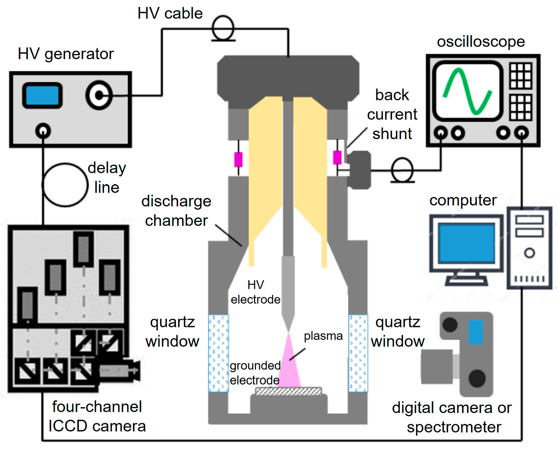
Figure 1 shows a schematic of the setup used in the experiments. High-voltage voltage pulses of negative polarity were applied to an interelectrode gap via a 2- or 5-m-length high-voltage, 75-Ω-cable connecting a generator and a discharge chamber. Voltage pulses were produced by generators made of all-solid-state switches [25]. The generators (Table 1) used in the experiments were NGP-18/3500N (Megaimpulse Ltd., Burbach, St. Petersburg, Russia) and GIN-100-1 (FID GmbH, Burbach, Germany).
This discharge chamber was previously used in another study [24]. A diode was formed by a high-voltage cathode with a small radius of curvature and a flat grounded anode. The cathode was made of a 5-mm-diameter steel rod with a pointed end, and the anode was made of a 25-mm-diameter and 1-mm-thick copper plate. The discharge plasma was formed at a gap width, d, of 4 to 10 mm. In some experiments, the anode surface was covered with a layer of carbon black with a thickness of approximately 10–40 µm. To cover the carbon layer on the anode surface, diluted gas from ordinary lighters was burned under it. The size of individual particles discernible using a microscope was no more than 1 μm [24]. The discharge chamber was filled with ambient air at atmospheric pressure.
The discharge plasma emission was output through side quartz windows. A Canon EOS R2 digital camera (Canon Ltd., Tokyo, Japan) was used to take time-integrated images of the plasma emission. A high-speed four-channel HSFC-PRO ICCD camera (PCO Computer Optics GmbH, Kelheim, Germany) was used to take time-resolved images. The ICCD camera took up to four consecutive images per discharge implementation. The minimum exposure duration of each channel was 3 ns. The ICCD camera was triggered by a sync signal from the high-voltage generator.
Voltage pulses were measured using a 0.014-Ω back-current shunt based on low-inductance SMD resistors. The waveforms of the electrical signals were recorded with a TDS MDO3102 digital oscilloscope (Tektronix Inc., Beaverton, OR, USA) with a bandwidth of 1 GHz and a sampling rate of 5 GS/s. The procedures for data acquisition and analysis were performed using a desktop computer.
3. Results
3.1. Excitation Conditions
It is well known that plasma formed during nanosecond gas discharges has variable impedance. Prior to breakdown, the impedance is infinite, resulting in the idling mode where a voltage pulse is reflected by the gap. The voltage pulse travels along a transmission line from the generator to the gap and backward. This is repeated until the energy has been dissipated. The high-voltage 75-Ω-cable shown in Figure 1 served as a transmission line. For the diffuse discharge, matching the plasma impedance with that of the transmission line can be achieved by adjusting the gap width and/or the amplitude of the applied voltage pulse. However, for spark discharge, a mode with low-resistance discharge plasma is implemented, which is almost like a short circuit. When using NGP-18/3500N or GIN-100-1 generators with d = 4 mm, no discharge constriction occurs during the first pulse. However, it could occur when the first or subsequent reflected pulses arrive at the gap. Below, images of diffuse and spark discharges are presented. The impedance of the discharge gap becomes much less than that of the transmission line when a spark channel is formed. In addition, after the voltage pulse is formed, the internal impedance of the generator decreases to a value significantly less than the wave impedance of the transmission line. The inconsistency of the impedance of the setup elements led to multiple reflections of the voltage pulse occurring, both from the gap and the generator. Due to the energy losses accompanying reflections, the pulse amplitude decreases. The number of reflected pulses and their polarity depend on the plasma impedance. During the diffuse discharge, the plasma impedance is greater than that of the transmission line, and the voltage pulse is reflected without polarity inversion. Then, the reflected voltage pulse reverses its polarity when it is reflected from the generator. The delay between pulses in the waveform is determined by the length of the transmission line. This mode is described in more detail in [26], where the tracks of glowing particles between two electrodes with a small radius of curvature were studied.
This study focuses on the features of the discharge operation in the gap with d = 4–6 mm when the combustion of a carbon black (soot) layer on the surface of the flat grounded electrode is observed. For the 4-mm gap fed by the GIN-100-1 voltage pulse generator, the waveforms of the voltage across the gap and the discharge current through it during the arrival of the first nanosecond voltage pulse were reconstructed on the basis of the incident and reflected voltage waves (Figure 2a). Note that the incident wave was measured by us earlier and was used to calculate the reflected wave from the signal recorded with the back-current shunt. Then, the voltage across the gap was determined. Knowing the incident and reflected waves, it is easy to estimate the power/energy stored in the incident wave (Figure 2b), as well as the power/energy deposited into the discharge plasma (Figure 2c). With the energy stored in the incident wave being approximately 16 mJ, the energy deposited into the discharge plasma during the first pulse is approximately 10 mJ. It should be noted that 40% of the energy is carried away by the reflected pulse since the gap operates in idle mode initially. The energy input into the plasma did not depend on the material of the electrodes or whether the anode was covered with carbon black or not.
3.2. Time-Integrated Discharge Plasma Glow
During the experiments, it was found that as the carbon black layer thickness increases and the distance between the electrodes decreases to less than 8 mm, the composition and shape of the discharge emission in the gap are altered.
The time-integrated images show luminous objects that differ in color from the plasma emission, as well as the individual spots and tracks of particles. A bright glowing layer is observed on the surface of the grounded electrode coated with carbon black (Figure 3a,b), while no emission is observed on the surface of the grounded electrode free from carbon (Figure 3c). Earlier, such emission was mentioned in our paper [24]. The metal anode surface is cleared of carbon black after 1–3 discharge cases, depending on the layer thickness.
Reducing the distance between the electrodes to 4 mm results in a discharge mode where flame plumes arise from the surface of the grounded flat electrode coated with carbon black (Figure 4). The thicker the carbon black layer, the more impressive the flame plume. In Figure 4c, it looks like wings or a trident. The complex shape of the flame plumes indicates the presence of vortices caused by post-discharge gas-dynamic flows caused by pressure gradients. The occurrence of flame plumes is believed to be due to the combustion of the carbon layer on the surface of the flat grounded electrode. This, in turn, is confirmed by the fact that neither a bright glowing near-electrode layer nor plums are observed when using metal electrodes free from any coatings.
It should be noted that in the experiments, both diffuse and spark discharges could be formed at the same gap width, regardless of the presence of a carbon black layer. Sparks can occur due to the development of thermal-ionization instabilities at high specific energy input (see, e.g., Refs. [27,28,29]). A spark discharge against the background of the diffuse one can be seen in the time-integrated images for the 4-mm gap width with the flat electrode coated with carbon black and the electrode free from it (Figure 5). Discharge constriction does not prevent the appearance of flame plumes, but the emission intensity of the spark channel is typically higher. No flame plumes are present in the absence of a carbon black layer (Figure 5c), as seen in the case of the diffuse discharge.
3.3. Discharge Glow Dynamics with and without Carbon Black on the Anode Surface
This section presents the time-resolved ICCD images that illustrate the discharge development dynamics in the 4-mm gap. The presented data pertain to both diffuse and spark discharges. Although the images produced by the ICCD camera are in grayscale, various formations in the gap can be distinguished by the glowing shapes. Figure 6 displays the discharge plasma emission during the first and second voltage pulses, as well as the integral image of that for 750 μs after the appearance of the first voltage pulse at the gap for the metal flat electrode not covered with carbon black.
From Figure 6a, it can be seen that during the first (main) voltage pulse, the diffuse discharge is implemented. Bright cathode spots are visible on the pointed electrode. At the arrival of the second pulse (the first reflected one), a bright spark channel is observed in the second frame (Figure 6b). Figure 6c, obtained with an exposure of 1 ms, shows an increase in the intensity of the spark channel radiation and its expansion. The intensity of the diffuse discharge plasma emission appears to be much lower than that of the spark channel (Figure 6a vs. Figure 6b). This is entirely due to the extremely short emission phase of a nanosecond excitation pulse duration [12]. When the flat grounded electrode is coated with a layer of carbon black under the same excitation conditions, a bright luminous layer near its surface is observed (Figure 7).
During the first pulse, a diffuse discharge accompanied by bright spots on the pointed cathode is formed (Figure 7a). The arrival of the first reflected pulse at the gap leads to the development of spark channels (Figure 7b). A relatively weak glow is observed near the grounded electrode surface. Flame plumes are seen in Figure 7c, taken at a 1-ms exposure.
It is important to note that the shape of the flames in the ICCD images corresponds to that in the time-integrated images taken both during diffuse (Figure 4c) and spark discharge (Figure 5b).
The brightly glowing layer near the flat electrode surface is formed before the flame plumes. According to experimental data, this occurs within the first 20 ns after the incident voltage wave arrives at the gap, and then the propagation process of flame plumes into the interelectrode space begins (Figure 8).
Figure 8a demonstrates the fact that the formation of the brightly glowing layer occurs at the stage of the diffuse discharge. The ICCD images in Figure 8b,c illustrate the process of the slow propagation of the flame plumes from the grounded electrode surface into the interelectrode space, resulting in the formation of ‘wings’ or a ‘trident’. When the carbon layer thickness was 40 µm, the probability of flame plume occurrence exceeded 50%.
Figure 9 shows the initial phase of flame plume development.
As mentioned above, the emission near the grounded electrode surface occurs within 20 ns after the formation of the diffuse discharge (Figure 9a). The diffuse discharge plasma glow is almost indistinguishable against the bright region occupied by flames that develop within fractions of microseconds after the breakdown. The movement speed of these flames varies from pulse to pulse and depends on the thickness of the carbon black layer, but the average value estimated from the ICCD images for the case of the diffuse discharge is ~60 m/s. The data in Figure 9 also confirm the conclusion that only the diffuse discharge energy is sufficient for the combustion of the carbon black layer on the grounded electrode surface.
4. Discussion
Many scientific groups have studied the ignition and combustion of different substances, including carbon and its compounds, in various states of aggregation (refer to [30,31,32,33,34,35,36,37] for more information). Let us analyze the results obtained.
The carbon black layer on the flat grounded electrode is ignited within 20 ns after the application of a high-voltage voltage pulse to the gap and the formation of the diffuse discharge (as shown in Figure 8a and Figure 9a,c). The ignition temperature of carbon in air varies depending on its state. For example, as the size of individual particles decreases, the temperature threshold for ignition also decreases, which is true for carbon. This effect may cause carbon black to ignite more quickly under these conditions; however, it is not the main factor. The sublimation threshold for graphite is too high, ~3630 °C, which is not achievable in this experiment with the energy input into the discharge at ≈10 mJ. It is believed that the presence of high-molecular hydrocarbons in the carbon black layer plays the main role in its ignition. The ignition of high-molecular hydrocarbons requires significantly less energy and lower temperatures compared with graphite. The rapid cooling of combustion products during carbon black layer application promotes the formation of high-molecular hydrocarbons on the flat copper electrode. No carbon combustion was observed when using a flat electrode made of dense graphite. Based on the fact that carbon ignition occurs during the diffuse discharge when the plasma temperature is still low and close to room temperature, it can be assumed that the process is possible due to the presence of a high concentration of various excited atoms and oxygen molecules in the plasma of the diffuse discharge. These elements are responsible for the oxidation process of carbon. This hypothesis can be tested by implementing a discharge, for example, in pure nitrogen. It is worth noting that hot electrode spots formed during the explosion of microprotrusions due to the high current density in them can also provide the initial impetus for the ignition process.
5. Conclusions
In this study, the conditions and dynamics of flame plumes in the form of intricate structures that occur during a nanosecond discharge in air above an electrode coated with a layer of carbon black are investigated. The flame plumes are the result of carbon black combustion initiated by plasma treatment. The study showed that carbon combustion can occur both in spark and diffuse discharges. To understand the dynamics of the discharge and flame development processes, a four-channel ICCD camera was used. It was revealed that the ignition of carbon black occurs within 20 nanoseconds, right after the first voltage pulse. This rapid ignition is probably made possible by the formation of excited atoms and oxygen molecules of high concentrations. However, it is important to note that the electrode surface may not only contain pure carbon particles but also high-molecular compounds of carbon and hydrogen formed during the combustion of gasoline when the carbon black layer is applied to the electrode. To ignite carbon black in the discharge gap volume during a diffuse discharge, a specific energy input of 1 MW/cm3 and more is sufficient. For surface ignition, the discharge current density must exceed 50 A/cm2 with a pulse duration of 5 ns at half maximum. To obtain these data, we used the results of our previous work [24]. The results of the research demonstrate that a diffuse nanosecond discharge in air at atmospheric pressure can be effectively utilized as a non-invasive method for cleaning surfaces from soot contamination.
Author Contributions
Conceptualization, writing—original draft, V.T. and M.L.; investigation and methodology, M.L.; validation and formal analysis, M.L., V.T., D.S. and D.B.; supervision, review and editing D.S. and D.B. All authors have read and agreed to the published version of the manuscript.
Funding
This research was performed within the framework of the state assignment of the IHCE SB RAS, project No. FWRM-2021-0014.
Institutional Review Board Statement
Not applicable.
Informed Consent Statement
Not applicable.
Data Availability Statement
Data are contained within the paper.
Conflicts of Interest
The authors declare no conflicts of interest.
References
- Kefeng, S.; Wang, M.; Peng, B.; Li, J.; Lu, N.; Jiang, N.; Wu, Y. Characterization of a novel volume-surface DBD reactor: Discharge characteristics, ozone production and benzene degradation. J. Phys. D Appl. Phys. 2019, 53, 065201. [Google Scholar] [CrossRef]
- Pang, W.; Li, Y.; DeLuca, L.T.; Liang, D.; Qin, Z.; Liu, X.; Xu, H.; Fan, X. Effect of Metal Nanopowders on the Performance of Solid Rocket Propellants: A Review. Nanomaterials 2021, 11, 2749. [Google Scholar] [CrossRef] [PubMed]
- Adamovich, I.; Agarwal, S.; Ahedo, E.; Alves, L.L.; Baalrud, S.; Babaeva, N.; Bogaerts, A.; Bourdon, A.; Bruggeman, P.J.; Canal, C.; et al. The 2022 Plasma Roadmap: Low temperature plasma science and technology. J. Phys. D Appl. Phys. 2022, 55, 373001. [Google Scholar] [CrossRef]
- Huang, J.; Zhu, Y.; Guo, S.; Guo, L.; Yu, W.; Akram, S.; Zhu, X.; Cui, X.; Fang, Z. Surface treatment of large-area epoxy resin by water-perforated metal plate electrodes dielectric barrier discharge: Hydrophobic modification and uniformity improvement. Appl. Surf. Sci. 2023, 639, 158166. [Google Scholar] [CrossRef]
- Dieringa, H. Properties of magnesium alloys reinforced with nanoparticles and carbon nanotubes: A review. J. Mater. Sci. 2011, 46, 289–306. [Google Scholar] [CrossRef]
- Mehrizi, M.K.; Mortazavi, S.M.; Mallakpour, S.; Bidoki, S.M.; Vik, M.; Vikova, M. The effect of carbon black nanoparticles on some properties of air plasma printed cotton/polyamide 6 fabrics. Fibers Polym. 2013, 14, 1620–1626. [Google Scholar] [CrossRef]
- Kalered, E.; Brenning, N.; Pilch, I.; Caillault, L.; Minéa, T.; Ojamäe, L. On the work function and the charging of small (r ≤ 5 nm) nanoparticles in plasmas. Phys. Plasmas 2017, 24, 013702. [Google Scholar] [CrossRef]
- Andronov, A.; Budylina, E.; Shkitun, P.; Gabdullin, P.; Gnuchev, N.; Kvashenkina, O.; Arkhipov, A. Characterization of thin carbon films capable of low-field electron emission. J. Vac. Sci. Technol. B 2018, 36, 02C108. [Google Scholar] [CrossRef]
- Slobodian, O.M.; Okholin, P.N.; Lytvyn, P.M.; Malyuta, S.V.; Khyzhun, O.Y.; Vasin, A.V.; Rusavsky, A.V.; Gomeniuk, Y.V.; Glotov, V.I.; Nazarova, T.M.; et al. Plasma treatment as a versatile tool for tuning of sorption properties of thin nanoporous carbon films. Appl. Surf. Sci. 2021, 544, 148876. [Google Scholar] [CrossRef]
- Tardiveau, P.; Moreau, N.; Bentaleb, S.; Postel, C.; Pasquiers, S. Diffuse mode and diffuse-to-filamentary transition in a high pressure nanosecond scale corona discharge under high voltage. J. Phys. D Appl. Phys. 2009, 42, 175202. [Google Scholar] [CrossRef]
- Babich, L.P. High-Energy Phenomena in Electric Discharges in Dense Gases: Theory, Experiment and Natural Phenomena; Futurepast: Arlington, VA, USA, 2003; p. 358. [Google Scholar]
- Tarasenko, V.F. (Ed.) Generation of Runaway Electron Beams and X-rays in High Pressure Gases, Volume 1: Techniques and Measurements; Nova Science Publishers: New York, NY, USA, 2016; p. 405. [Google Scholar]
- Tarasenko, V.F. (Ed.) Generation of Runaway Electron Beams and X-rays in High Pressure Gases, Volume 2: Processes and Applications; Nova Science Publishers: New York, NY, USA, 2016; p. 315. [Google Scholar]
- Shao, T.; Zhang, C. (Eds.) Pulsed Discharge Plasmas: Characteristics and Applications; Springer Nature: Singapore, 2023; p. 1034. [Google Scholar] [CrossRef]
- Erofeev, M.; Lomaev, M.; Ripenko, V.; Shulepov, M.; Sorokin, D.; Tarasenko, V. Generators of Atmospheric Pressure Diffuse Discharge Plasma and Their Use for Surface Modification. Plasma 2019, 2, 27–38. [Google Scholar] [CrossRef]
- Almazova, K.I.; Belonogov, A.N.; Borovkov, V.V.; Gorelov, E.V.; Morozov, I.V.; Tren’kin, A.A.; Kharitonov, S.Y. Microstructure of a Spark Discharge in Air in a Point-Plane Gap. Tech. Phys. 2018, 63, 801–805. [Google Scholar] [CrossRef]
- Parkevich, E.V.; Ivanenkov, G.V.; Medvedev, M.A.; Khirianova, A.I.; Selyukov, A.S.; Agafonov, A.V.; Mingaleev, A.R.; Shelkovenko, T.A.; Pikuz, S.A. Mechanisms responsible for the initiation of a fast breakdown in an atmospheric discharge. Plasma Sources Sci. Technol. 2018, 27, 11LT01. [Google Scholar] [CrossRef]
- Parkevich, E.V.; Medvedev, M.A.; Khirianova, A.I.; Ivanenkov, G.V.; Selyukov, A.S.; Agafonov, A.V.; Shpakov, K.V.; Oginov, A.V. Extremely fast formation of anode spots in an atmospheric discharge points to a fundamental ultrafast breakdown mechanism. Plasma Sources Sci. Technol. 2019, 28, 125007. [Google Scholar] [CrossRef]
- Tren’kin, A.A.; Almazova, K.I.; Belonogov, A.N.; Borovkov, V.V.; Gorelov, E.V.; Morozov, I.V.; Kharitonov, S.Y. Dynamics of the initial stage of the spark and diffuse discharges in air in a point–plane gap at different parameters of the tip electrode. Tech. Phys. 2019, 64, 470–474. [Google Scholar] [CrossRef]
- Almazova, K.I.; Belonogov, A.N.; Borovkov, V.V.; Kurbanismailov, V.S.; Khalikova, Z.R.; Omarova, P.K.; Ragimkhanov, G.B.; Tereshonok, D.V.; Trenkin, A.A. Investigation of the microchannel structure in the initial phase of the discharge in air at atmospheric pressure in the “pin (anode)-plane” gap. Phys. Plasmas 2020, 27, 123507. [Google Scholar] [CrossRef]
- Almazova, K.I.; Belonogov, A.N.; Borovkov, V.V.; Kurbanismailov, V.S.; Ragimkhanov, G.B.; Tren’kin, A.A.; Tereshonok, D.V.; Khalikova, Z.R. Plasma and Gas-Dynamic Near-Electrode Processes in the Initial Phase of a Microstructured Spark Discharge in Air. Tech. Phys. Lett. 2020, 46, 737–740. [Google Scholar] [CrossRef]
- Almazova, K.I.; Belonogov, A.N.; Borovkov, V.V.; Khalikova, Z.R.; Ragimkhanov, G.B.; Tereshonok, D.; Trenkin, A.A. Investigation of plasma properties in the phase of the radial expansion of spark channel in the pin-to-plate geometry. Plasma Sources Sci. Technol. 2021, 30, 095020. [Google Scholar] [CrossRef]
- Rep’ev, A.G.; Repin, P.B.; Pokrovskiĭ, V.S. Microstructure of the current channel of an atmospheric-pressure diffuse discharge in a rod-plane air gap. Tech. Phys. 2007, 52, 52–58. [Google Scholar] [CrossRef]
- Lomaev, M.; Tarasenko, V.; Shulepov, M.; Beloplotov, D.; Sorokin, D. Nano-and Microparticles of Carbon as a Tool for Determining the Uniformity of a Diffuse Discharge Exposure. Surfaces 2023, 6, 40–52. [Google Scholar] [CrossRef]
- Efanov, V.M.; Efanov, M.V.; Komashko, A.V.; Kriklenko, A.V.; Yarin, P.M.; Zazoulin, S.V. Ultra-Wideband, Short Pulse Electromagnetics; Springer: New York, NY, USA, 2010; pp. 301–305. [Google Scholar]
- Tarasenko, V.F.; Beloplotov, D.V.; Panchenko, A.N.; Sorokin, D.A. Thin Luminous Tracks of Particles Released from Electrodes with A Small Radius of Curvature in Pulsed Nanosecond Discharges in Air and Argon. Surfaces 2023, 6, 214–226. [Google Scholar] [CrossRef]
- Korolev, I.D.; Kuzmin, V.A.; Mesiats, G.A. Nanosecond Gas Discharge in an Inhomogeneous Field with Explosive Processes on the Electrodes. Sov. Phys. Technol. Phys. 1980, 25, 418–420. [Google Scholar]
- Janda, M.; Machala, Z.; Niklová, A.; Martišovitš, V. The streamer-to-spark transition in a transient spark: A dc-driven nanosecond-pulsed discharge in atmospheric air. Plasma Sources Sci. Technol. 2012, 21, 045006. [Google Scholar] [CrossRef]
- Shao, T.; Tarasenko, V.F.; Zhang, C.; Lomaev, M.I.; Sorokin, D.A.; Yan, P.; Kozyrev, A.V.; Baksht, E.K. Spark discharge formation in an inhomogeneous electric field under conditions of runaway electron generation. J. Appl. Phys. 2012, 111, 023304. [Google Scholar] [CrossRef]
- Starikovskiy, A.; Aleksandrov, N. Plasma-assisted ignition and combustion. Prog. Energy Combust. Sci. 2013, 39, 61–110. [Google Scholar] [CrossRef]
- Riaza, J.; Gibbins, J.; Chalmers, H. Ignition and combustion of single particles of coal and biomass. Fuel 2017, 202, 650–655. [Google Scholar] [CrossRef]
- Watson, A.Y.; Valberg, P.A. Carbon black and soot: Two different substances. AIHAJ-Am. Ind. Hyg. Assoc. 2001, 62, 218–228. [Google Scholar] [CrossRef] [PubMed]
- Long, C.M.; Nascarella, M.A.; Valberg, P.A. Carbon black vs. black carbon and other airborne materials containing elemental carbon: Physical and chemical distinctions. Environ. Pollut. 2013, 181, 271–286. [Google Scholar] [CrossRef] [PubMed]
- Misyura, S.Y. Comparing the dissociation kinetics of various gas hydrates during combustion: Assessment of key factors to improve combustion efficiency. Appl. Energy 2020, 270, 115042. [Google Scholar] [CrossRef]
- Michelsen, H.A.; Colket, M.B.; Bengtsson, P.E.; D’anna, A.; Desgroux, P.; Haynes, B.S.; Miller, J.H.; Nathan, G.J.; Pitsch, H.; Wang, H. A review of terminology used to describe soot formation and evolution under combustion and pyrolytic conditions. ACS Nano 2020, 14, 12470–12490. [Google Scholar] [CrossRef]
- Pal, Y.; Palateerdham, S.K.; Mahottamananda, S.N.; Sivakumar, S.; Ingenito, A. Combustion performance of hybrid rocket fuels loaded with MgB2 and carbon black additives. Propuls. Power Res. 2023, 12, 212–226. [Google Scholar] [CrossRef]
- Weiser, V.; Eisenreich, N. Fast emission spectroscopy for a better understanding of pyrotechnic combustion behavior. Propellants Explos. Pyrotech. Int. J. Deal. Sci. Technol. Asp. Energetic Mater. 2005, 30, 67–78. [Google Scholar] [CrossRef]
Figure 1.
Schematic of the experimental setup.

Figure 2.
(a) Reconstructed voltage across the gap and discharge current. (b) Calculated power and energy in the incident wave. (c) Calculated power and energy deposited into the discharge plasma during the first voltage pulse when the grounded electrode was covered with carbon black. GIN-100-1 voltage pulse generator. Air pressure is 1 atm. Gap width is d = 4 mm.

Figure 3.
Time-integrated images of diffuse discharge in air at a pressure of 1 atm and at the gap width of 6 mm. (a,b) Grounded electrode covered with a 20-µm carbon layer. (c) No carbon black layer. NPG-18/3500N voltage pulse generator. PE—pointed electrode. GE—grounded electrode.
Figure 3.
Time-integrated images of diffuse discharge in air at a pressure of 1 atm and at the gap width of 6 mm. (a,b) Grounded electrode covered with a 20-µm carbon layer. (c) No carbon black layer. NPG-18/3500N voltage pulse generator. PE—pointed electrode. GE—grounded electrode.

Figure 4.
Time-integrated images of the diffuse discharge in air at a pressure of 1 atm and a gap width of 4 mm. Grounded electrode covered with black carbon layer with thicknesses of (a) 20 µm, (b) 30 µm, and (c) 40 µm. NPG-18/3500N voltage pulse generator. Metal electrodes. PE—pointed electrode.
Figure 4.
Time-integrated images of the diffuse discharge in air at a pressure of 1 atm and a gap width of 4 mm. Grounded electrode covered with black carbon layer with thicknesses of (a) 20 µm, (b) 30 µm, and (c) 40 µm. NPG-18/3500N voltage pulse generator. Metal electrodes. PE—pointed electrode.

Figure 5.
Time-integrated images of spark discharge in air at a pressure of 1 atm and at a gap width of 4 mm. (a,b) Grounded electrode covered with a 30-µm carbon layer. (c) No carbon black layer. NPG-18/3500N voltage pulse generator. PE—pointed electrode.
Figure 5.
Time-integrated images of spark discharge in air at a pressure of 1 atm and at a gap width of 4 mm. (a,b) Grounded electrode covered with a 30-µm carbon layer. (c) No carbon black layer. NPG-18/3500N voltage pulse generator. PE—pointed electrode.
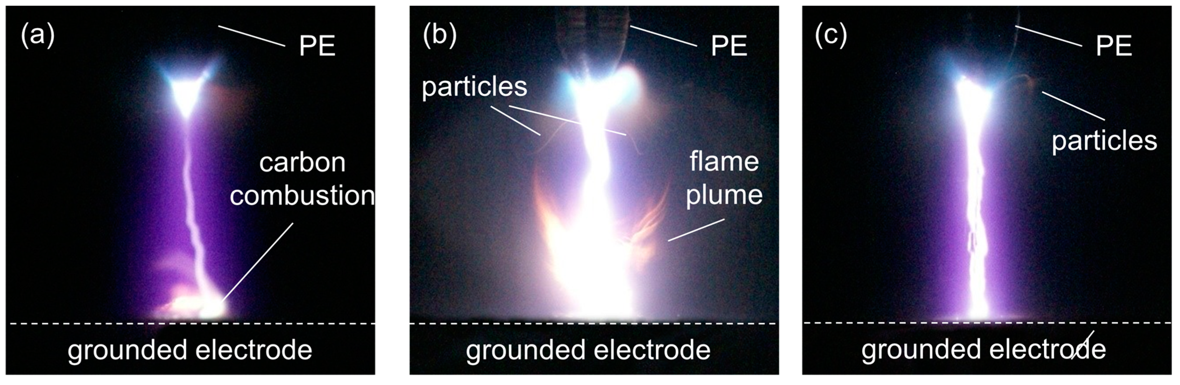
Figure 6.
ICCD images of discharge development in air at a pressure of 1 atm and a gap width of 4 mm, taken at different exposure durations: (a) 10 ns, (b) 20 ns, with a delay relative to the first image of 25 ns, and (c) 1 ms (after the first pulse). No carbon black layer on the grounded electrode. GIN-100-1 voltage pulse generator. PE—pointed electrode.

Figure 7.
ICCD images of discharge development in air at a pressure of 1 atm and a gap width of 4 mm, taken at different exposure durations: (a) 10 ns, (b) 20 ns, with a delay relative to the first image of 25 ns, and (c) 1 ms (after the first pulse). Grounded electrode covered with a 30-µm carbon black layer. GIN-100-1 voltage pulse generator. PE—pointed electrode.
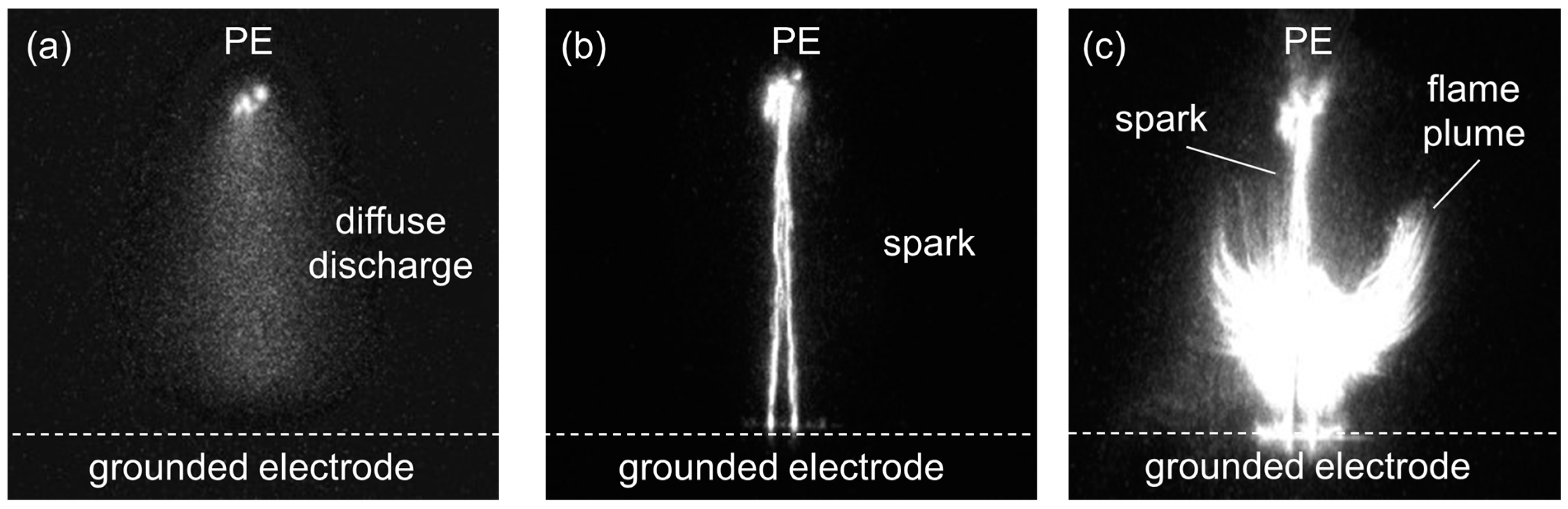
Figure 8.
ICCD images of discharge development in air at a pressure of 1 atm and a gap width of 4 mm, taken at different exposure durations: (a) 20 ns, (b) 1.5 ms, and (c) 50 ms. Grounded electrode covered with a 40-µm carbon black layer. GIN-100-1 voltage pulse generator. PE—pointed electrode.
Figure 8.
ICCD images of discharge development in air at a pressure of 1 atm and a gap width of 4 mm, taken at different exposure durations: (a) 20 ns, (b) 1.5 ms, and (c) 50 ms. Grounded electrode covered with a 40-µm carbon black layer. GIN-100-1 voltage pulse generator. PE—pointed electrode.
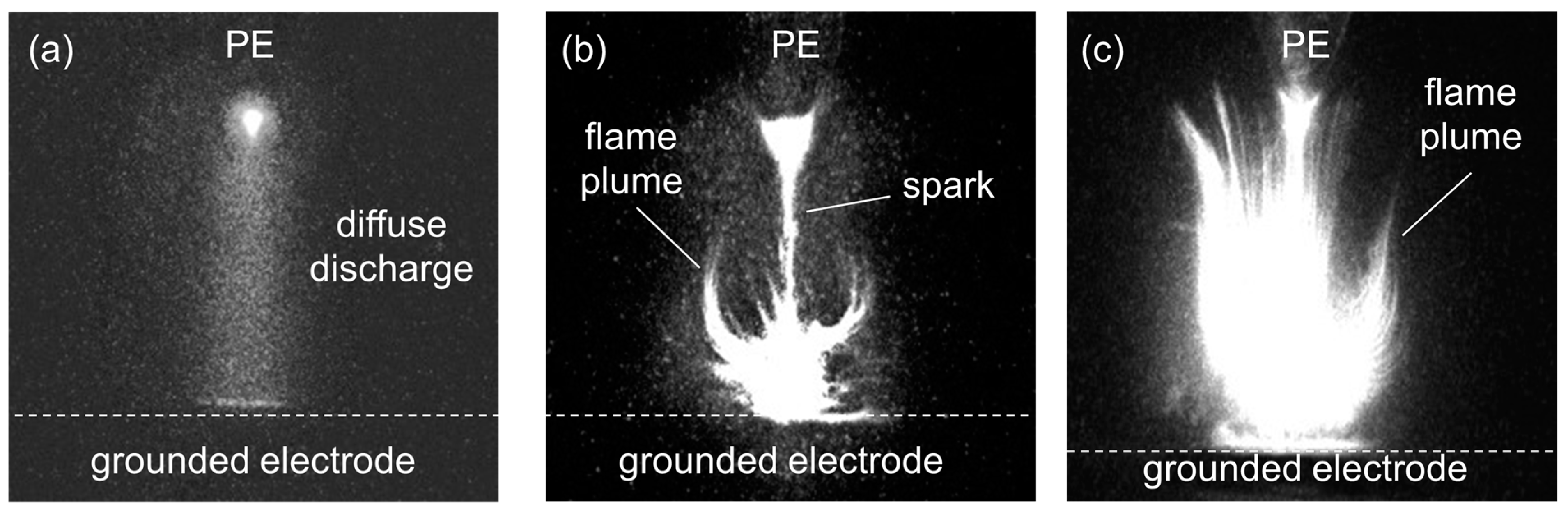
Figure 9.
ICCD images of discharge development in air at a pressure of 1 atm and a gap width of 4 mm, taken at different exposure durations: (a) 20 ns, (b) 0.5 µs, (c) 1 µs, and (d) 10 µs. The delays relative to the moment of applying the voltage pulse from the generator to the gap were 0, 0.5, 1, and 10 μs, respectively, for (a–d). The grounded electrode covered with a 40-µm carbon black layer. GIN-100-1 voltage pulse generator. PE—pointed electrode.


Table 1.
Characteristics of a voltage pulse * produced by generators in the experiments.
| Model | Amplitude, kV | Duration **, ns | Rise Time, ns |
|---|---|---|---|
| NGP-18/3500N | 18 | 8.0 | 4.0 |
| GIN-100-1 | 20 | 4.5 | 2.5 |
* The characteristics relate to an incident voltage wave. ** Full width at half-maximum.
Disclaimer/Publisher’s Note: The statements, opinions and data contained in all publications are solely those of the individual author(s) and contributor(s) and not of MDPI and/or the editor(s). MDPI and/or the editor(s) disclaim responsibility for any injury to people or property resulting from any ideas, methods, instructions or products referred to in the content. |
© 2024 by the authors. Licensee MDPI, Basel, Switzerland. This article is an open access article distributed under the terms and conditions of the Creative Commons Attribution (CC BY) license (https://creativecommons.org/licenses/by/4.0/).
Share and Cite
MDPI and ACS Style
Lomaev, M.; Tarasenko, V.; Sorokin, D.; Beloplotov, D. Ignition of Carbon Black during Nanosecond Diffuse and Spark Discharges in Air at Atmospheric Pressure. Surfaces 2024, 7, 44-53. https://doi.org/10.3390/surfaces7010004
AMA Style
Lomaev M, Tarasenko V, Sorokin D, Beloplotov D. Ignition of Carbon Black during Nanosecond Diffuse and Spark Discharges in Air at Atmospheric Pressure. Surfaces. 2024; 7(1):44-53. https://doi.org/10.3390/surfaces7010004
Chicago/Turabian StyleLomaev, Mikhail, Victor Tarasenko, Dmitry Sorokin, and Dmitry Beloplotov. 2024. "Ignition of Carbon Black during Nanosecond Diffuse and Spark Discharges in Air at Atmospheric Pressure" Surfaces 7, no. 1: 44-53. https://doi.org/10.3390/surfaces7010004