Article

Improving the Mechanical and Electrochemical Performance of Additively Manufactured 8620 Low Alloy Steel via Boriding

1
School of Engineering and Technology, Central Michigan University, Mount Pleasant, MI 48859, USA
2
Mechanical Engineering, Indiana University-Purdue University Columbus, Columbus, IN 47203, USA
*
Author to whom correspondence should be addressed.
Corros. Mater. Degrad. 2023, 4(4), 623-643; https://doi.org/10.3390/cmd4040032
Submission received: 6 September 2023 / Revised: 14 October 2023 / Accepted: 26 October 2023 / Published: 6 November 2023

Abstract

:
In this study, mechanical and electrochemical performance of borided additively manufactured (AM) and wrought 8620 low alloy steel were investigated and compared to their bare counterparts. The microstructure of borided 8620 exhibited the presence of FeB and Fe2B phases with a saw tooth morphology. Both AM and wrought samples with boride layers showed a similar performance in hardness, wear, potentiodynamic polarization (PD), electrochemical impedance spectroscopy (EIS), and linear polarization resistance (LPR) experiments. However, borided steels exhibited about an 8-fold increase in Vickers hardness and about a 6-fold enhancement in wear resistance compared to bare ones. Electrochemical experiments of borided specimens (both AM and wrought) in 0.1 M Na2S2O3 + 1 M NH4Cl solution revealed a 3–6-fold lower corrosion current density, about a 6-fold higher charge transfer resistance, and about a 6-fold lower double-layer capacitance, demonstrating an improved corrosion resistance compared to their bare counterparts. Post-corrosion surface analysis revealed the presence of thick sulfide and oxide layers on the bare steels, whereas dispersed corrosion particles were observed on the borided samples. The enhanced wear and electrochemical performance of the borided steels were attributed to the hard FeB/Fe2B layers and the reduced amount of adsorbed sulfur on their surface.

1. Introduction

Wear and corrosion are the two major causes of material degradation and failure in many industrial applications. For example, automotive components, such as gear, camshaft, crankshaft, piston pin, etc., suffer from wear-induced material loss due to cyclic nature of their loading [1,2,3,4]. In addition, intricate parts in the oil and gas industries, such as valve seat, pump impeller, and plunger of sucker rod pumps, are susceptible to wear and corrosion due to the presence of CO2, H2S, and other corrosive media [5,6]. Material degradation has also been reported in pulp and paper industries, where the presence of H2S gas generated from thiosulfate causes uniform, pitting, fatigue, and stress corrosion [7,8]. Chloride ion ( Cl ) , particularly in the form of NH4Cl, is also a potentially hazardous corrosive element for oil refinery equipment and pipelines [9].
To address material degradation and wear, chemical vapor deposition (CVD), physical vapor deposition (PVD), thermochemical treatment, plasma spraying, plasma oxidizing, and sol–gel method are some of the surface treatment technologies that are being commonly used to create exceptionally hard, wear-resistant, and corrosion-resistant surfaces [10,11,12]. Hot-dip galvanizing, a surface-coating method, is the most extensively used corrosion prevention technique for steel due to its simplicity. However, in terms of energy consumption and harsh chemical usage, this practice is particularly harmful to the environment. Apart from these fabrication issues, galvanized steel does not offer a significant improvement in wear performance and may result in lower hardness [13,14,15]. In this regard, boriding, a thermochemical process, can be used on steel to simultaneously produce better wear and fracture- and corrosion-resistant components [16]. Boriding process can be classified into three broad groups based on the physical state of the boriding agent: gaseous boriding, liquid boriding, and solid pack and paste boriding [13,17,18]. However, only the pack and paste boriding procedures have gained widespread applications due to their ease of use, whereas the other techniques are less commonly used due to toxicity concerns [19,20]. In paste boriding, boron atoms diffuse into the substrate from surrounding boron-rich paste, creating a hard and wear- and corrosion-resistant layer. A borided surface has a hardness of 1300 to 2300 HV, which is higher than that of hard chromium coatings or hardened tool steels [21]. Another noteworthy characteristic of the borided surface is that it shows an excellent wear resistance up to 650 °C and retains its hardness even after a further heat treatment up to 1000 °C [21,22,23].
Alloying elements affect the diffusivity of boron in steel, resulting in an alteration in the thickness of the borided layer. Carbon, molybdenum, and tungsten, for example, have a significant impact on the borided layer thickness, whereas silicon, chromium, and aluminum have a moderate impact, and nickel, manganese, and cobalt have just a little impact on the boride layer thickness [24]. Low alloy steel, such as AISI 8620, is hence an excellent choice for the application of boriding due to its low alloy content. It is a preferred choice amongst other steels for its higher toughness [25] and better machinability [26], which makes it a preferred choice for various industrial applications. It also offers excellent ductility [27,28], making it resilient to impacts and vibrations. The ability to fine-tune its mechanical properties through heat treatment further underscores its suitability for a wide range of applications, from gears and shafts to structural components. In addition, this steel is available, affordable, and adaptable for industrial use [29].
Conventional manufacturing of the above-mentioned components creates a lot of material waste and poses restrictions on design flexibility. On the other hand, additive manufacturing (AM) techniques, such as Selective Laser Melting (SLM), Selective Laser Sintering (SLS), Electron Beam Melting (EBM), etc., are being adopted in automotive and oil and gas industries as emerging technologies to fabricate functional components due to their inherent design flexibility, rapid manufacturing, and cost competitiveness for small-to-medium batch production [30,31,32]. AM is also capable of fabricating large complex shapes. For example, Wire Arc Additive Manufacturing (WAAM) is distinguished by its ability to deposit material rapidly, its cost-effectiveness, and its straightforward maintenance [33,34]. This demonstrates the versatility of AM techniques.
SLM is a layer-by-layer manufacturing process where a thin layer of powder is laid down with a roller spreader on the build platform of a 3D printer. Then, the metal powder is selectively melted using a laser beam, with CAD data defining the coordinates of the melt boundary. Once a layer has been melted, the build chamber is lowered according to the system-determined layer thickness, and the procedure is repeated until the desired item has been manufactured. In the SLM process, laser power, laser scanning speed, hatch distance, and powder layer thickness can have a significant impact on the finished product quality. Parts manufactured using the SLM technology are denser and have higher mechanical qualities than those made using the SLS approach because the powder is fully melted during the manufacturing process [35]. Additionally, SLM produces components with finer microstructure than EBM [36].
The corrosion resistance of different borided steels and alloys, such as AISI 304, low-carbon steel, AISI H13, high-manganese steel, IN718, and C276, have been investigated in different corrosive environments, such as NaCl, HCl, H2SO4, H3PO4, and molten salt, using different methods [37,38,39,40,41]. Borided AISI 304, low-carbon steel, and high-manganese steel exhibited enhanced corrosion resistance in NaCl solution signified by the lower corrosion current density and higher electropositive corrosion potential. Nickel-based borided alloys such as IN718, and C276 exhibited a better corrosion resistance in molten salt containing chloride ions. However, borided H13 steel showed a deteriorated corrosion resistance in an acidic environment containing a solution of HCl, H2SO4, and H3PO4 in long-term (up to 350 h) immersion tests. No specific reason was reported to explain this behavior of borided H13 steel. Additionally, borided steels, e.g., AISI 316L, AISI 1018, 31CrMoV9, and X40CrMoV5-1 steels, exhibited an improved wear performance and a superior hardness compared to bare steels [42,43,44]. An et al. investigated the corrosion behavior of borided 8620 steel in H2S-saturated oil field water and reported a significant improvement in corrosion resistance [45]. The corrosion resistance of borided 8620 steel, specifically of additively manufactured 8620, however, has not been studied in a H2S-rich medium in the presence of chloride ions. Experiments with H2S gas need highly expensive equipment and containment systems to assure safety due to the poisonous, combustible, and corrosive nature of the gas. Non-toxic chemicals, such as sodium thiosulfate, have been suggested as a safe alternative to generate H2S in an aqueous media of chemical and electrochemical reactions [46,47].
In this research, mechanical and electrochemical properties of Selective Laser Melted (SLMed) AISI 8620 low alloy steel with and without boriding were investigated and compared to those of the wrought counterparts. Phase analysis of the bare and borided samples was conducted via X-Ray Diffraction (XRD). Microhardness and dry-sliding wear tests were conducted to investigate their mechanical behavior, whereas potentiodynamic polarization (PD), electrochemical impedance spectroscopy (EIS), and linear polarization resistance (LPR) tests were conducted in 0.1 M Na2S2O3 + 1 M NH4Cl electrolyte to explore their electrochemical properties. Characterization of their corrosion products and corroded surface were performed with scanning electron microscope (SEM) and energy-dispersive spectroscopy (EDS).

2. Materials and Methods

2.1. Sample Preparation

The substrate materials used in this study were Selective Laser Melted (SLMed) and wrought 8620 low alloy steels. The powder of the SLM process was supplied by Renishaw® (USA), and the wrought 8620 was purchased from Alro® (USA). The compositions of the powder and wrought sample are shown in Table 1.
The powder diameter followed a normal distribution between 8.5 µm and 59 µm, with a mean diameter of 31.5 µm and a standard deviation of 11.1 µm (Figure 1a). A disc-shaped CAD model of 15 mm diameter and 5 mm thickness was designed in SOLIDWORKS®, 2019, and used as the data file for the printer.
Before the start of the printing process, the build plate was heated to a temperature of 170 °C. To achieve an inert atmosphere inside the build chamber, the oxygen content was brought down to as low as 0.1% with a vacuum pump and then a high-grade argon gas was introduced. The samples were printed in a way such that the flat surface of the disc, i.e., the test surface, was parallel to the build direction, as shown in Figure 1b. A 1060 nm Ytterbium laser (180 W) with a spot size of 75 µm was employed for the printing. The layer thickness was 50 µm, and the hatch spacing was 110 µm, respectively. Each layer was divided into 5 mm × 5 mm square blocks, and a checkerboard hatching approach was used to melt the layers. Each square block was scanned using parallel lines that were rotated 90° with respect to its neighboring block. To achieve a minimal temperature gradient in the bulk volume, each layer (n + 1) was rotated 67° in relation to the previous layer (n). The SLMed and wrought samples were mechanically sanded with sanding papers from 80 grit to 1200 grit, cleaned with ethanol in an ultrasonication bath, and dried in the air prior to boriding at 1500 °F using Materials Development Corporation’s (Andover, MA, USA) proprietary Borofuse® technology.

2.2. Material Characterization

Bare SLMed and wrought samples were further mirror polished on polishing cloth with 3 μm and 1 μm diamond suspensions and etched with a 5% Nital (5% Nitric Acid and 95% Ethanol) solution to reveal their grain boundaries. Hitachi S-3400-II Scanning Electron Microscope (SEM) and Cascade Microtech M150 Optical Microscope (OM) were used for their microstructural characterization. Their crystallographic orientations and constitutional phases were studied using Rigaku Ultima IV XRD using Cu-Kα radiation (1.5408 Å) with 2θ angle ranging from 10° to 90° with a step size of 0.02° at a speed of 1 °/min. The same surface preparation technique was followed to characterize the boride layers as well. The thickness values of the boride layers were calculated using a 12-measurement average technique following the procedure stated elsewhere [48]. The elemental composition of the corrosion products was analyzed via an EDS analyzer integrated with the SEM. Volume fractions of the phases were calculated using imageJ (version 1.53k) software.

2.3. Hardness Test

Microhardness measurements were performed using a Clark CM ARS 9000 testing system with a Vickers indenter using a 50 gf load and 12 s dwell time. Microhardness values were measured at 6 points, starting at a distance of 25 µm from the edge of the borided sample, and each point was separated by a distance of 25 µm.

2.4. Wear Test

Wear tests of the borided and bare SLMed 8620 samples were carried out with a pin-on-disk Tribometer from Anton Paar (CSM Instruments), USA, under unlubricated conditions at room temperature (21–23 °C). The disks for the wear test were fabricated with a diameter of 30 mm and a thickness of 5 mm to adhere to the ASTM G99 test standard [49]. Prior to the wear test, bare samples were mechanically sanded using sanding papers ranging from 80 to 1200 grit, washed with ethanol in an ultrasonication bath, and dried in the air. Identical preparations were conducted for the borided samples before the boriding process. No surface changes were made after boriding to keep the borided layers intact. The pin was fabricated from 52100 Carbon Steel (CS52100) with a tip diameter of 9.525 mm. For each sample, the wear test was conducted once for 1 h with a load of 20 N and a linear velocity of 0.3 m/s over a total sliding distance of 1069 m. Eight to eleven surface profiles were processed and analyzed with surface analysis software “Mountains 7.4” from Digital Surf to calculate the average wear rate and mass loss with standard deviation. The rate of wear was calculated as the volume of material lost per sliding distance and per unit of load. The worn surfaces of the samples were analyzed using a scanning electron microscope (SEM) after each wear test to evaluate the wear mechanism.

2.5. Electrochemical Test

Electrochemical analyses of the bare and borided 8620 were conducted in 0.1 M Na2S2O3 + 1 M NH4Cl solution simulating an oil and gas environment. A Gamry Reference 1000E potentiostat was used to conduct electrochemical experiments on SLMed and wrought (bare and borided) samples. In a three-electrode cell, 8620 steel was used as the working electrode, with a platinum coil serving as the counter electrode and a saturated calomel electrode working as the reference. All potentials were recorded at room temperature.
To prepare the electrolyte, 0.1 M Na2S2O3 and 1 M NH4Cl solutions were prepared separately by dissolving 15.81 g of Na2S2O3 and 53.49 g of NH4Cl (both purchased from Fisher Scientific®, USA), and each was separately dissolved in 1000 mL of high-purity Milli-Q water. The resulting Na2S2O3 and NH4Cl solutions were mixed and used in all electrochemical experiments. The pH of 0.1 M Na2S2O3, 1 M NH4Cl, and 0.1 M Na2S2O3 + 1 M NH4Cl solutions were 6.72, 5.31, and 5.63, respectively.
The open-circuit potential (OCP) was measured for 2 h before all electrochemical tests to allow the system to stabilize. Potentiodynamic polarization test was conducted by sweeping the potential from −0.5 V vs. OCP to +1.5 V vs. OCP at a scanning rate of 1 mV/s. Corrosion potential and corrosion current density were determined from Tafel plots using the Tafel extrapolation method. The EIS measurements were conducted in the frequency range from 100 kHz to 10 mHz using a 5 mV sinusoidal potential modulation of the open-circuit potential, recording 10 data points per decade. The linear polarization resistance (LPR) was measured at a scanning rate of 0.125 mV/s from −20 to 20 mV vs. OCP. The working electrode had an exposed surface area of 1 cm2 in all these tests. The reproducibility of the results was ensured by repeating all the tests at least three times. SEM was used to characterize the corroded surface following the potentiodynamic polarization test.

3. Results and Discussion

3.1. Microstructure

The microstructural images of bare SLMed and wrought 8620 are shown in Figure 2a–c. The microstructure of bare SLMed 8620 consisted of needle-shaped lath martensite dispersed in the matrix, resulting from an elevated cooling rate of the SLM process, as shown in Figure 2a. Due to the high solidification rate of the SLM process, melted powder during each laser scan had insufficient time to transform to ferrite. However, successive laser scans re-melted and reheated a small portion of the previous layer creating a region of tempered martensite, which could be observed between the dashed lines in the side view of the SLMed specimen, as shown in Figure 2b. The trapped carbon atoms in this reheated area came out from the crystals and precipitated as carbides near the grain boundaries [50].
Wrought 8620, on the other hand, showed a ferritic and pearlitic microstructure (as shown in Figure 2c), which was entirely different than that of the SLMed 8620. The ferrite grains and pearlite colonies were found to be evenly distributed throughout the matrix. Slow cooling of pro-eutectoid steel was responsible for the formation of this kind of microstructure. Table 2 represents the volume fraction of different phases in the bare and borided steels.
XRD patterns of the bare SLMed and wrought 8620 samples (as shown in Figure 3a) exhibited distinct peaks at 2θ locations of 44.63°, 64.87°, and 82.21°, which correspond to alpha ferrite (110), (200), and (211) crystalline orientations, respectively. Similar peaks in wrought 8620 have been reported in other studies as well [27,51]. BCT (Body-Centered Tetragonal) and BCC (Body-Centered Cubic) structures show similar peaks in XRD, and thus, these two phases are not distinguishable with XRD. Differences in the relative intensities of ferrite peaks were observed for bare SLMed and wrought samples. Though the preferred orientation in both cases was the (110) plane, the intensity in the bare SLMed sample was comparatively lower. It is also worth noting that the intensity of the (211) peak in the wrought sample was greater than that of the (200) peak. However, in the bare SLMed sample, these peaks had around the same intensity, indicating that these two planes were distributed equally.
The XRD pattern of the borided SLMed 8620 is displayed in Figure 3b. Boride layers formed on the substrates consisted mainly of FeB and Fe2B. However, due to the high thickness (50.2 ± 4.1 µm) of the FeB phase compared to the Fe2B phase, the XRD signals from Fe2B phase were very mild. This dual phase boride formation was expected due to the high temperature used during the boriding process, and this two-phase boride formation has been reported in other studies for wrought 8620 as well [45,52,53]. No peak shift was observed in any of the samples. Most of the peaks matched with reference peaks. However, a slight variation was observed that is common in experimental studies. The lattice parameters of different phases were calculated using Bragg’s law and are reported in Table 3.
The tetragonal structure of the SLMed sample exhibited a slight elongation. However, this is expected because of the small percentage of carbon (0.19%) in 8620 steel. The c value was compared with ref [54], and it was within 0.46% error. Other lattice parameters were compared with Crystallography Open Database (COD) reference values, and those were under 0.30% error.

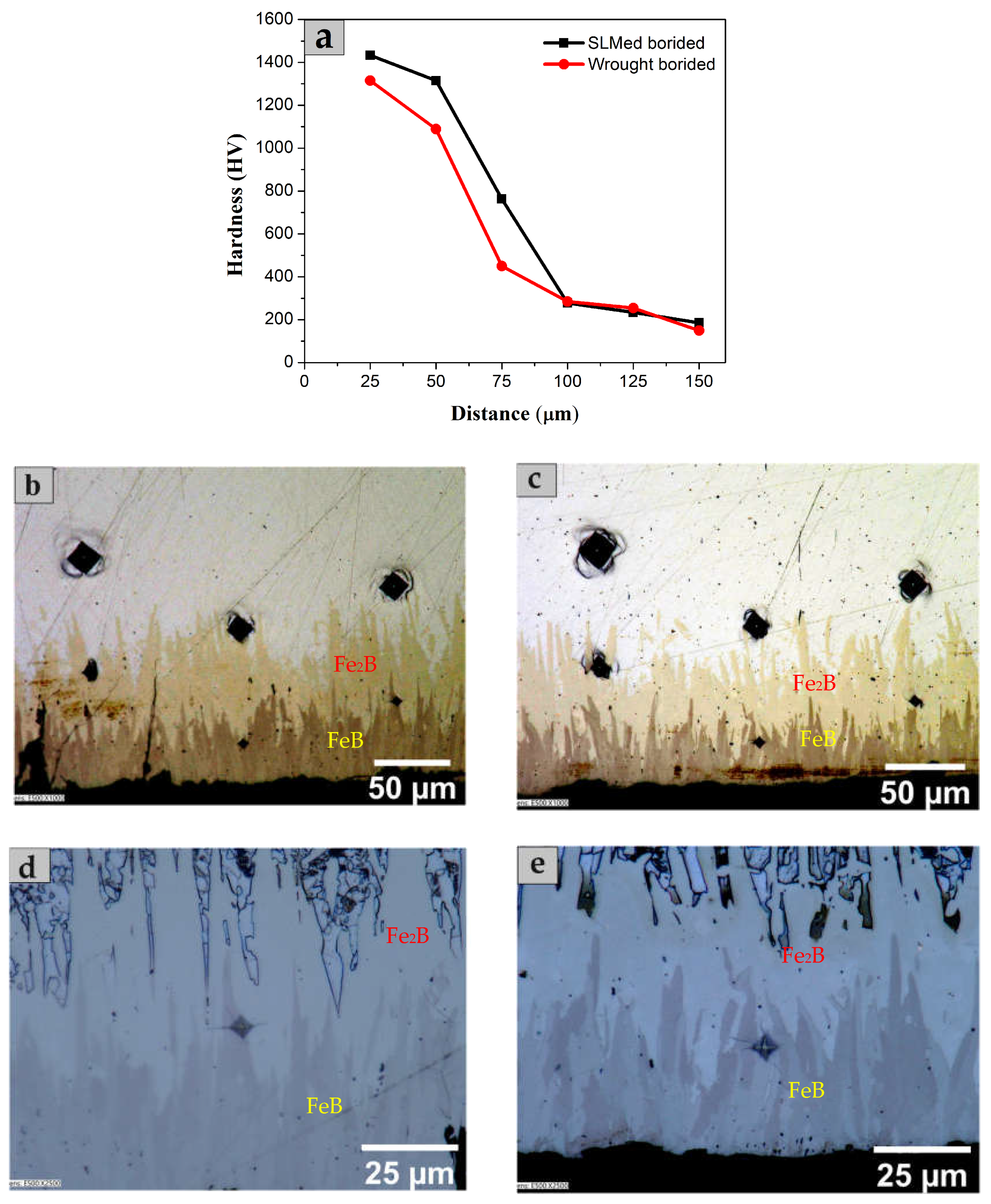
3.2. Characterization of Boride Layer

Cross-sectional SEM images of boride layers over SLMed and wrought 8620 are presented in Figure 4. The microstructure exhibited a homogeneously distributed layer with three distinct regions: (i) an outermost layer of FeB and Fe2B, (ii) a transition region with dispersed boride particles, and (iii) a steel substrate. The formation of boride layers starts with boron atoms diffusing into the steel from the boron-rich medium surrounding the sample. When a suitable boron concentration is reached at some point on the steel’s surface, Fe2B crystals begin to nucleate, forming a surface layer composed of Fe2B. As boron continues to diffuse into the Fe2B crystal, and the boron concentration reaches a higher level, the FeB phase begins to form [55]. It has been reported that the Fe2B phase occurs when the boron concentration in the steel surface reaches about 9 wt% [53,56], and when the boron concentration reaches 16 wt%, the FeB phase develops on top of the Fe2B layer, resulting in a two-phase iron boride layer [17].
Among the two phases of iron borides, the dark-colored FeB phase was present near the edge of the cross-section, and the light-colored Fe2B phase was present just beneath it. No gaps, cracks, or cavities were found in the boride layer, suggesting a good adhesion between the boride layer and the substrate. The transition layer exhibited a saw-tooth structure developed from the overlapping of boride crystals, creating high-stress regions, and compelling the borides to expand into the steel perpendicular to the sample surface [53,56]. Because of this kind of morphology, the boride layer is strongly attached to the substrate [52].
The thickness of the borided layer is a function of the boriding time, temperature, boron concentration, and composition of the base material [57,58]. In both SLMed and wrought samples, the Fe2B and FeB layers were of similar thickness, indicating a similar growth mechanism. It is concluded that the starting microstructure of martensite in SLMed and ferrite and pearlite in wrought sample, respectively, did not contribute to any difference in the boride layer formation due to the recrystallization at the high temperature of the boriding process. However, the martensitic microstructure of the substrate transformed to the ferritic and pearlitic microstructure due to the slow cooling after the boriding process. The total thickness of the boride layer was 111 ± 15.2 µm and 101.2 ± 14.5 µm, whereas the thickness of the FeB layer was 50.2 ± 4.1 µm and 49.4 ± 5.6 µm, in borided SLMed and wrought 8620, respectively.

3.3. Hardness Test

Figure 5a shows the microhardness depth profiles across the cross-sections of the borided SLMed and wrought 8620. Since microhardness measurements close to the edge (within ~20 µm) are not representative of the true hardness values [59], the hardness measurement was started at 25 µm away from the edge (Figure 5b,c). Borided SLMed and wrought 8620 did not exhibit a significant variation in their hardness profiles. Near the edge, the borided SLMed 8620 had a hardness value of 1433 HV, while the borided wrought sample had a hardness value of 1315 HV. These values are consistent with the orthorhombic crystalline structure of FeB, which has a normal hardness of 1400 ± 200 HV [13], and the tetragonal body-centered structure of Fe2B, which has a typical hardness of 1300 ± 100 HV [13]. As the distance from the edge increased, the hardness values dropped to 185 HV and 149 HV for SLMed and wrought samples, respectively, reaching the hardness values of the substrates. The transition zone below the boride layers was softer than the boride layers but harder than the metal substrate due to the presence of diffused boron and dispersed boride particles in the zone.
Cracks were visible at the hardness-indentation corners of both SLMed and wrought 8620 during microhardness measurement of the boride layer (Figure 5d,e), and this fact supports the brittle nature of the boride phase. Similar observations have been reported in other studies as well [18]. The FeB phase is more brittle and possesses a lower fracture toughness than Fe2B, which results in severe flaking and spalling when a large normal or shear stress is applied [13]. Moreover, the difference in coefficient of thermal expansion of these two phases causes high tensile stresses in the FeB phase and compressive stresses in the Fe2B phase, which leads to crack formation at the phase interface during specimen cooling after the boriding treatment. For these reasons, a monolayer Fe2B is preferable over a FeB/Fe2B bilayer [13,55]. Different techniques, e.g., changing the composition of boronizing powder [17,60,61], the thickness of boronizing paste [62], boronizing temperature [63], etc., have been adopted so far to fabricate a monolayer Fe2B phase. For SLMed 8620, controlling the process temperature seems to be the most appropriate technique for growing a Fe2B monolayer.

3.4. Wear Test

Figure 6a shows the wear rate of borided and bare SLMed 8620 that demonstrated the enhanced wear resistance of borided steel. The wear rate of borided SLMed 8620 was 0.84 ± 0.33 × 10⁻⁵ mm3/Nm, whereas the bare SLMed showed a wear rate of 5.58 ± 1.69 × 10⁻⁵ mm3/Nm. Hence, the wear resistance of SLMed 8620 was increased by a factor of six as a consequence of the boriding treatment. The wear rate values correspond to a mass loss of 1.41 ± 0.55 mg and 9.38 ± 2.85 mg, respectively (Figure 6b). Under identical conditions, Paraye et al. evaluated the wear rate of bare wrought 8620 and found a mass loss of 25.9 ± 2 mg for a sliding velocity of 1 m/s [64]. In this experiment, a sliding velocity of 0.3 m/s was used and thus a reduced wear rate was observed. The wear rate of borided wrought 8620 has been reported in other studies; however, the test conditions were entirely different than those of the current study [45,53]. The reported results showed the enhanced wear resistance of borided wrought compared to that of bare counterparts, which was attributed to the continuous and adherent hard boride layers (FeB/Fe2B) on top of the sample.
SEM micrographs of the worn surfaces of the borided and bare SLMed 8620 steels are presented in Figure 6c,d. Abrasion was the major mechanism of wear on the bare sample, as demonstrated by large parallel grooves and scratches along the motion direction in Figure 6c. These grooves can be attributed to micro-cutting and micro-plowing actions between the sliding bodies [65,66]. In micro-plowing, abrasive particles create a groove on the wearing surface without removing any material, whereas, in micro-cutting, the abrasive particle serves as a cutting tool, and a chip is formed in front of its cutting edge as a result of the impact [67]. These wear mechanisms are indicative of the soft nature of the bare SLMed 8620. On the other hand, the presence of a rough worn surface on the borided 8620 demonstrated an adhesive wear mode [1]. In adhesive wear, small areas of two sliding surfaces were welded and subsequently ruptured at the welding points. These worn-out particles thus formed remained attached either momentarily or permanently, leaving a rough surface on the test sample. Formation of cracks were also observed on the worn borided surface as shown in Figure 6d. The mechanical stresses created by Hertzian forces in the interaction zone are responsible for crack development and propagation on hard and brittle surfaces [23]. Furthermore, the existence of grooves on the worn surface of the borided specimen was not noticed due to its increased hardness.
Figure 6e,f present the trend of the coefficient of friction (CoF) with sliding distance. The average CoF was determined as a mean value along the complete scratch distance. The borided and bare SLMed 8620 had an average CoF of approximately 0.551 and 0.527, respectively. The borided sample showed a steady increase in the CoF up to ~150 m, which corresponded to the smoothing of the initial roughness of the borided surface. The oscillatory behavior at a sliding distance of 150–300 m might indicate crack formation on the FeB layer. After this region, the CoF reached a steady-state value. At a sliding distance of 870–1070 m, the oscillatory behavior might imply crack development on the Fe2B layer. Arteaga-Hernandez et al. reported a similar wear behavior of the FeB/Fe2B layers in a dry sliding test [42]. The CoF of the bare SLMed was almost stable after the initial irregularities. Once the asperities were polished by abrasive wear, the CoF did not change significantly. It is worth mentioning that the coefficient of friction is largely affected by surface characteristics, such as surface roughness, hardness, lubrication conditions, and local chemical interactions at the wear couple’s interface [68,69].

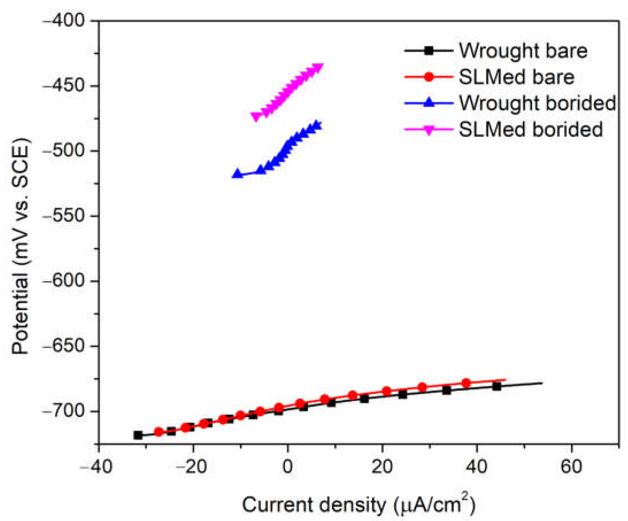
3.5. Potentiodynamic Polarization

Figure 7 shows the open-circuit potential, and Figure 8a presents the potentiodynamic polarization curves of borided and bare 8620 steels (both SLMed and wrought) in 0.1 M Na2S2O3 + 1 M NH4Cl electrolyte at room temperature.
The electrochemical parameters, such as corrosion potential (Ecorr), corrosion current density (Icorr), Tafel slopes (βA and βC), and polarization resistance (Rp), extracted from potentiodynamic polarization curves using Gamry Echem Analyst (version 7.04) software are reported in Table 4. The Rp values were calculated using the Stern–Geary equation [70] provided in Equation (1).
R P = β A β C 2.303   β A + β C   i c o r r
where 2.303 is a constant. Furthermore, the corrosion inhibiting efficiency (ɛresistance) of the borided layers was calculated by the following equation [38] and reported in the same table:
ɛ r e s i s t a n c e = i c o r r 0 i c o r r i c o r r 0 × 100 %
where
i c o r r 0 is the corrosion current density of the bare 8620, and
i c o r r is the corrosion current density of the borided 8620.
Table 4. Quantitative data extracted from Tafel extrapolation of potentiodynamic polarization scan (n = 3).
SampleEcorr (mV)Icorr (µA/cm2)βA (mV/decade)βC (mV/Decade)Rp (Ω·cm2)ɛresistance (%)
Wrought borided−452.7 ± 10.79.2 ± 1.9123.1 ± 9.1542.5 ± 117.34812 ± 55063.1
SLMed borided−553.3 ± 34.04.2 ± 1.2157.7 ± 35.1272.7 ± 60.710,535 ± 241182.8
Wrought bare−731.7 ± 0.624.9 ± 2.791.5 ± 7.0178.9 ± 12.41059 ± 70-
SLMed bare−716.7 ± 8.124.4 ± 1.085.2 ± 1.8196.7 ± 30.21054 ± 25-
The polarization curves in Figure 7a depict an enhancement in the electrochemical behavior of borided steel in the chloride–thiosulfate solution. One of the main findings from these polarization curves is that Ecorr values shifted towards the positive potential in borided samples compared to those of their bare counterparts. In particular, the Ecorr value demonstrated a positive shift of around 279 mV and 163 mV in borided wrought and SLMed 8620, compared to the bare counterparts, respectively. This implies that, within these particular corrosion environments, boriding can function as a protective barrier against material degradation for the 8620 steel. Furthermore, Icorr values reduced by an order of magnitude, registering 9.2 ± 1.9 µA/cm2 and 4.2 ± 1.2 µA/cm2 in borided wrought and SLMed 8620, compared to 24.9 ± 2.7 µA/cm2 and 24.4 ± 1.0 µA/cm2, respectively, in their bare counterparts.
Corrosion current densities of borided and bare wrought 8620 in H2S-saturated water were evaluated by An et al., and they reported their similar corrosion current densities [52]. The reduced current densities in borided 8620 signify the lower corrosion susceptibility of borided samples in the tested electrolyte.
Sodium thiosulfate was chosen due to its non-toxic nature and its capability to produce hydrogen sulfide gas, representative of the environment found in the oil and gas industries. The cathodic reaction in the polarization curve corresponded to the evolution of H2S, which was confirmed by the rotten egg smelling gas formation during the experiment. The electrochemical reactions happening in this period have been reported in other studies [71,72]:
S 2 O 3 2 + 6 H + + 4 e 2 S + 3 H 2 O
S 2 O 3 2 + H + S + H S O 3
S + 2 H + + 2 e   H 2 S
In the anodic scan, the oxidation of metallic substrate was the dominant reaction producing metal sulfides. Sulfur was adsorbed on the metal surface and later formed a metal sulfide via the following reactions [73]:
M + S 2 O 3 2 + H 2 O M S a d s + S O 4 2 + 2 H + + 2 e where   M   =   Fe ,   Ni   or   Cr
xM-Sads + (y − x)S → MxSy (sulfide)
The presence of Cl ion accelerated the anodic current by forming oxides on the steel surface. The electrochemical reactions responsible for the oxide formation were determined and reported by Jiang et al. [38]:
F e + 2 C l + 4 H 2 O   F e C l 2 .4 H 2 O + 2 e
O 2 + 2 H 2 O + 4 e   4 O H
F e C l 2   .4 H 2 O + 2 O H   F e O H 2 + 2 C l + 4 H 2 O
4 F e O H 2 + 2 H 2 O + O 2 4 F e O H 3
Thus, the film of corrosion products consisted of sulfides and oxides of metal species. However, none of the samples demonstrated a distinct passive region in the chloride–thiosulfate electrolyte. This could be due to the presence of metal sulfides in the layer of corrosion products, which is more porous than a pure oxide film [74]. As a result, the porous corrosion layer was unable to entirely shield the underlying metal, resulting in uniform corrosion rather than pitting. Therefore, both Cl and S 2 O 3 2 ions had a significant impact on the corrosion mechanism. It is worth noting that the corrosion mechanism is heavily influenced by alloy composition and S 2 O 3 2 / Cl concentration ratio 73 . Being a low alloy steel, 8620 lacks a sufficient amount of oxide formers such as Cr, Ni, and Mo, making it difficult to passivate in a chloride-thiosulfate environment.
The activation of anodic dissolution of the bare metal surface occurs by the development of a layer of adsorbed sulfur (Sads) on the dissolving surface as described earlier in Equation 6 [7]. The catalytic effect of this adsorbed sulfur on anodic dissolution has been shown in other studies [75,76,77]. The weakening of metal–metal bonds by the adsorbed sulfur, which lowers the activation energy of dissolution by creating oppositely charged dipoles on sulfur and metal, is assumed to be the reason for accelerated metal dissolution [7,78]. In addition, the adsorbed sulfur blocks the hydroxyl ions’ adsorption sites, which are the precursors for the formation of the passive layer [75]. In borided samples, FeB/Fe2B decreases this activating effect of sulfur by preventing the formation of adsorbed sulfur, which in turn lowers the metal dissolution rate. Thus, the enhanced electrochemical performance of borided 8620 can be attributed to the lack of adsorbed sulfur layer on the borided surface.

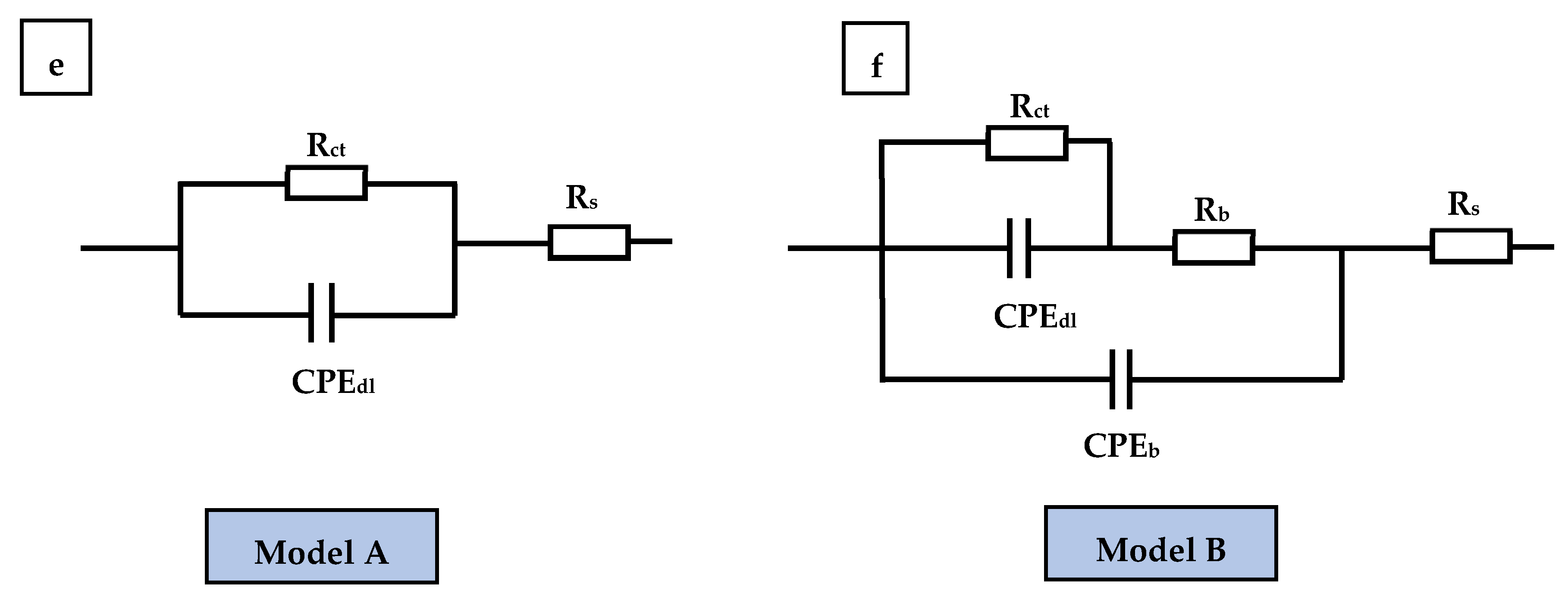
3.6. Electrochemical Impedance Spectroscopy

Figure 8b–d display EIS test results in 0.1 M Na2S2O3 + 1 M NH4Cl conducted over a frequency range from 10 mHz to 100 kHz at room temperature. In Bode impedance plots (Figure 8b), borided 8620 exhibited a significantly higher total impedance (|Z|) than bare samples, indicating enhanced barrier properties of the boride layer in 8620 steel. The phase angles, as shown in Figure 8c, of both borided and bare 8620 shifted from near zero (at 1 kHz–10 kHz) to more negative at a lower frequency (at 0.3 Hz–3 Hz). This implies that, at the higher frequency, the surface/electrolyte system exhibited a resistive behavior, whereas, at the lower frequency, it showed a capacitive behavior. However, the capacitive behavior differed from an ideal capacitor (ZPhase = −90°), which can be attributed to the surface heterogeneities [79]. The impedance spectra of Nyquist plots (Figure 8d) were made up of depressed semicircles. The greater the radius of the semicircle, the greater the resistance of a material, which is inversely related to corrosion rate [80]. The larger semicircle radii of the borided samples indicated a compact and continuous iron boride layer with minimal microporosities in the phases.
The quantitative electrochemical data were obtained using two equivalent electrical circuits (EEC), as shown in Figure 8e,f. Model A was employed for the bare samples due to the absence of passivation in such cases. Due to the existence of boride layers, borided steels could not be fit with model A; thus, a separate model, model B, was employed. In EEC, Rs represents the solution resistance; Rct and Rb are the charge transfer resistance of the electric double layer and resistance of the boride layer, respectively; CPEdl and CPEb are the constant phase elements to describe the dielectric behavior of the bare substrate and the boride layer. A parallel combination of Rct and CPEdl was used to represent the faradaic and non-faradaic processes at the electrode/electrolyte boundary. The impedance of the CPEb and CPEdl can be defined as follows:
Z C P E = Q j ω n 1
where j = 1 , refers to the imaginary component of the impedance, ω denotes the angular frequency, Q represents the imaginary admittance of CPE, and n denotes the exponent of CPE with a value 0 < n < 1.
The quantitative data acquired by fitting EIS spectra to each element in the EEC model are shown in Table 5. The goodness of fit was in the order of 10−3. The Rct value predicts a system’s corrosion resistance, and the borided SLMed and wrought (3763 ± 700 Ω·cm2 and 3457 ± 326 Ω·cm2, respectively) exhibited an approximately 6-fold higher charge transfer resistance than the bare SLMed and wrought (602 ± 58 Ω·cm2 and 648 ± 139 Ω·cm2), respectively. The total resistance Rt (=Rs + Rb + Rct) of borided SLMed and wrought (3970 ± 758 Ω·cm2 and 3700 ± 293 Ω·cm2) also demonstrated ~6 times increase than bare SLMed and wrought resistance values (675 ± 57 Ω·cm2 and 658 ± 136 Ω·cm2), respectively. Relatively lower Qdl values associated with borided SLMed (563 ± 46 μS-sn cm−2) and borided wrought samples (735 ± 92 μS-sn cm−2) indicated a lesser amount of charge relaxation [77] and an increase in thickness of the electrical double layer [81] of the borided sample than bare SLMed (2957 ± 726 μS-sn cm−2) and bare wrought (4347 ± 1180 μS-sn cm−2) 8620, respectively.

3.7. Linear Polarization Resistance

Figure 9 represents the linear polarization resistance (LPR) curves of SLMed and wrought 8620 with and without boride layers. The polarization resistance, Rp, was measured by considering the slope of the V vs. I curve near the OCP, and the borided 8620 exhibited a steeper slope compared to the bare one. In particular, borided SLMed and wrought 8620 exhibited Rp values of 4442 ± 1261 Ω·cm2 and 4286 ± 1206 Ω·cm2, respectively, which were 7-fold higher than the bare samples, i.e., Rp values of 656 ± 70 Ω·cm2 and 651 ± 136 Ω·cm2 for bare SLMed and wrought, respectively (Table 6). The higher polarization resistance of the borided samples signifies the protective capabilities of boride layers [82]. The corrosion current is inversely proportional to the polarization resistance; hence, a greater polarization resistance indicates a lesser corrosion tendency. In addition, the polarization resistance values were in close agreement with the resistance values obtained in the PD and EIS experiments (Table 4 and Table 5). There exist some variations in the data which could be due to the difference in the techniques utilized; however, the trend of polarization resistance is consistent across all cases, i.e., the polarization resistance values of borided 8620 were significantly higher than those of the bare 8620.
In summary, the corrosion resistance of SLMed and wrought 8620 was enhanced by the boride layer in 0.1 M Na2S2O3 + 1 M NH4Cl, according to the electrochemical parameters determined with the EIS and LPR tests, which was compatible with the findings of the potentiodynamic polarization experiments. The absence of metal–metal bond weakening adsorbed sulfur on the surface of the borided samples was responsible for the excellent corrosion resistance of the boride samples. Additionally, the improvement in electrochemical characteristics was attributable in part to the homogeneous and compact boride layers, which decreased the number of reaction sites, and therefore, improved the corrosion resistance [38].

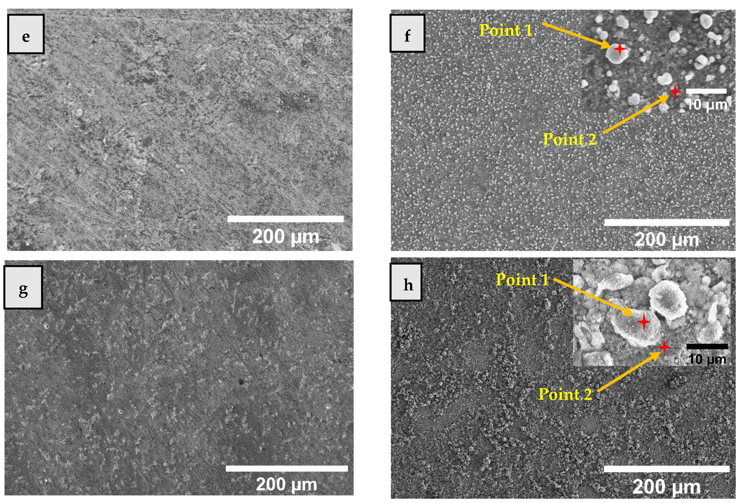
3.8. Surface Analysis after Potentiodynamic Polarization Test

Surface morphologies of the bare and borided 8620 after potentiodynamic polarization tests are presented in Figure 10. The surfaces of bare SLMed and wrought 8620 exhibited a thick layer of corrosion products (Figure 10b,d), whereas the borided counterparts showed evenly distributed granular corrosion particles (Figure 10f,h). The layer of corrosion products was similar on the bare surfaces and demonstrated a significant number of cracks, indicating its poor corrosion protection under corrosive environment. EDS point scans on the bare corroded surfaces confirmed the presence of Fe, Cr, Ni, S, and O, indicating that the corrosion products were composed of sulfides and oxides of metal species (Table 7). This kind of corrosion product formation was due to the chloride-induced oxidation of steel.
On the contrary, in borided SLMed and wrought 8620, sulfur was the dominating species in corrosion particles (i.e., point 1 in Figure 10f,h), signifying the presence of elemental sulfur (resulting from Equations (3) and (4)) on the surface. The borided surface lacks iron sulfides due to the presence of iron borides, which restrict the formation of adsorbed sulfur, and hence, the formation of iron sulfides. However, elemental sulfur can be deposited on the surface, which was observed not to accelerate the dissolution rate of metals. In both borided samples, the point scans away from the corrosion particle, i.e., point 2 in Figure 10f,h, and exhibits the presence of oxygen, high concentration of iron, and an insignificant amount of sulfur, indicating the formation of iron oxides on the surface. In summary, the enhanced corrosion resistance of borided 8620 can be attributed to the absence of adsorbed sulfur due to the protective nature of the FeB/Fe2B layers.

4. Conclusions

In this research, Selective Laser Melted (SLMed) and wrought 8620 steels were treated via boriding, and their mechanical and electrochemical behaviors were compared to those of their bare counterparts. The conclusions drawn are as follows:
  • Borided 8620 (both SLMed and wrought) exhibited an approximately 8-fold increase in Vickers hardness and an approximately 6-fold decrease in wear rate compared to bare 8620, which can be attributed to the formation of hard dual-phase iron boride layers.
  • The enhanced corrosion resistance of the borided SLMed and wrought 8620 in 0.1 M Na2S2O3 + 1 M NH4Cl solution were demonstrated by a 3–6-fold decrease in corrosion current density, an approximately 6-fold increase in charge transfer resistance, and an approximately 6-fold decrease in double-layer capacitance.
  • Post-corrosion surface characterization of the bare SLMed and wrought 8620 revealed the presence of a thick and porous layer of corrosion products, which predominantly comprised of sulfides and oxides of metal species.
  • Borided 8620 exhibited dispersed particles of corrosion products that predominantly comprised of elemental sulfur. The lower corrosion rate of the borided steels was attributed to the lower amount of adsorbed sulfur on the boride layers.

Author Contributions

Conceptualization, E.H.S. and I.S.; Methodology, E.H.S.; Formal analysis, E.H.S. and I.S.; Writing—original draft, E.H.S.; Writing—review & editing, E.H.S., M.N.-A.-A., W.H. and I.S.; Supervision, M.N.-A.-A., W.H. and I.S. All authors have read and agreed to the published version of the manuscript.

Funding

This research received no external funding.

Data Availability Statement

The data that support the findings of this study are available from the corresponding author upon reasonable request.

Acknowledgments

The authors would like to acknowledge the support from the College of Science and Engineering of Central Michigan University.

Conflicts of Interest

The authors declare no conflict of interest.

References

  1. Arslan, M.; Ok, A.C.; Kartal Sireli, G.; Timur, S. Investigation on Structural and Tribological Properties of Borided Gear Steel after Phase Homogenization. Surf. Coat. Technol. 2022, 429, 127967. [Google Scholar] [CrossRef]
  2. Bhosale, D.G.; Rathod, W.S.; Rukhande, S.W. Sliding Wear Behavior of High Velocity Oxy-Fuel Sprayed WC-Cr3C2-Ni Coating for Automotive Applications. Mater. Today Proc. 2019, 19, 339–343. [Google Scholar] [CrossRef]
  3. Bayrakceken, H.; Ucun, I.; Tasgetiren, S. Fracture Analysis of a Camshaft Made from Nodular Cast Iron. Eng. Fail. Anal. 2006, 13, 1240–1245. [Google Scholar] [CrossRef]
  4. Mateus, J.; Anes, V.; Galvão, I.; Reis, L. Failure Mode Analysis of a 1.9 Turbo Diesel Engine Crankshaft. Eng. Fail. Anal. 2019, 101, 394–406. [Google Scholar] [CrossRef]
  5. Medvedovski, E. Formation of Corrosion-Resistant Thermal Diffusion Boride Coatings. Adv. Eng. Mater. 2016, 18, 11–33. [Google Scholar] [CrossRef]
  6. El Hachem, K.; Kang, M. Methane and Hydrogen Sulfide Emissions from Abandoned, Active, and Marginally Producing Oil and Gas Wells in Ontario, Canada. Sci. Total Environ. 2022, 823, 153491. [Google Scholar] [CrossRef]
  7. Laycock, N.J. Effects of Temperature and Thiosulfate on Chloride Pitting of Austenitic Stainless Steels. Corrosion 1999, 55, 590–595. [Google Scholar] [CrossRef]
  8. Naghizadeh, M.; Nakhaie, D.; Zakeri, M.; Moayed, M.H. Effect of Thiosulfate on Pitting Corrosion of 316SS. J. Electrochem. Soc. 2015, 162, C71–C77. [Google Scholar] [CrossRef]
  9. Sliem, M.H.; Fayyad, E.M.; Abdullah, A.M.; Younan, N.A.; Al-Qahtani, N.; Nabhan, F.F.; Ramesh, A.; Laycock, N.; Ryan, M.P.; Maqbool, M.; et al. Monitoring of under Deposit Corrosion for the Oil and Gas Industry: A Review. J. Pet. Sci. Eng. 2021, 204, 108752. [Google Scholar] [CrossRef]
  10. Bindal, C.; Üçisik, A.H. Characterization of Borides Formed on Impurity-Controlled Chromium-Based Low Alloy Steels. Surf. Coat. Technol. 1999, 122, 208–213. [Google Scholar] [CrossRef]
  11. Yetim, T.; Turalioğlu, K.; Taftali, M.; Tekdir, H.; Kovaci, H.; Yetim, A.F. Synthesis and Characterization of Wear and Corrosion Resistant Ni-Doped Al2O3 Nanocomposite Ceramic Coatings by Sol-Gel Method. Surf. Coat. Technol. 2022, 444, 128659. [Google Scholar] [CrossRef]
  12. Tekdir, H.; Yetim, T.; Yetim, A.F. Corrosion Properties of Ceramic-Based TiO2 Films on Plasma Oxidized Ti6Al4V/316L Layered Implant Structured Manufactured by Selective Laser Melting. J. Bionic Eng. 2021, 18, 944–957. [Google Scholar] [CrossRef]
  13. Kartal Sireli, G.; Bora, A.S.; Timur, S. Evaluating the Mechanical Behavior of Electrochemically Borided Low-Carbon Steel. Surf. Coat. Technol. 2020, 381, 125177. [Google Scholar] [CrossRef]
  14. Šmak, M.; Kubíček, J.; Kala, J.; Podaný, K.; Vaněrek, J. The Influence of Hot-Dip Galvanizing on the Mechanical Properties of High-Strength Steels. Materials 2021, 14, 5219. [Google Scholar] [CrossRef] [PubMed]
  15. Taleb, A.; Labaïz, M.; Iost, A.; Montagne, A.; Ourdjini, A.; Grairia, A.; Meddah, S. Tribological Behaviour of a Continuous Hot Dip Galvanized Steel. Mater. Res. Express 2018, 6, 026579. [Google Scholar] [CrossRef]
  16. Uzun, Y.; Yanıkoğlu, N.; Kovacı, H.; Yetim, A.F.; Çelik, A. The Effects of Boriding on Metal-Ceramic Bond Strength of Co–Cr Alloy Fabricated by Selective Laser Melting. J. Adhes. Sci. Technol. 2021, 35, 1576–1591. [Google Scholar] [CrossRef]
  17. Spence, T.W.; Makhlouf, M.M. Characterization of the Operative Mechanism in Potassium Fluoborate Activated Pack Boriding of Steels. J. Mater. Process. Technol. 2005, 168, 127–136. [Google Scholar] [CrossRef]
  18. Joshi, A.A.; Hosmani, S.S. Pack-Boronizing of AISI 4140 Steel: Boronizing Mechanism and the Role of Container Design. Mater. Manuf. Process. 2014, 29, 1062–1072. [Google Scholar] [CrossRef]
  19. Suwattananont, N. Surface Treatment of Ferrous Alloys with Boron. Master’s Thesis, New Jersey Institute of Technology, Rutgers University, Newark, NJ, USA, 2004. [Google Scholar]
  20. Krelling, A.P.; Teixeira, F.; da Costa, C.E.; Almeida, E.A. dos S. de; Zappelino, B.; Milan, J.C.G. Microabrasive Wear Behavior of Borided Steel Abraded by SiO2 Particles. J. Mater. Res. Technol. 2019, 8, 766–776. [Google Scholar] [CrossRef]
  21. Atık, E.; Yunker, U.; Merıç, C. The Effects of Conventional Heat. Treatment and Boronizing on Abrasive Wear and Corrosion of SAE 1010, SAE 1040, D2 and 304 Steels. Tribol. Int. 2003, 36, 155–161. [Google Scholar] [CrossRef]
  22. Türkmen, İ.; Yalamaç, E.; Keddam, M. Investigation of Tribological Behaviour and Diffusion Model of Fe2B Layer Formed by Pack-Boriding on SAE 1020 Steel. Surf. Coat. Technol. 2019, 377, 124888. [Google Scholar] [CrossRef]
  23. Cimenoglu, H.; Atar, E.; Motallebzadeh, A. High Temperature Tribological Behaviour of Borided Surfaces Based on the Phase Structure of the Boride Layer. Wear 2014, 309, 152–158. [Google Scholar] [CrossRef]
  24. Selçuk, B.; Ipek, R.; Karamiş, M.B.; Kuzucu, V. An Investigation on Surface Properties of Treated Low Carbon and Alloyed Steels (Boriding and Carburizing). J. Mater. Process. Technol. 2000, 103, 310–317. [Google Scholar] [CrossRef]
  25. Boyle, E.; Northwood, D.O.; Bowers, R.; Sun, X.; Bauerle, P. The effects of initial microstructure and heat treatment on the core mechanical properties of carburized automotive steels. Mater. Forum 2007, 32, 44–54. [Google Scholar]
  26. Verdeja, L.F.; Verdeja, J.I.; González, R. Machinability Improvement Through Heat Treatment In 8620 Low-Carbon Alloyed Steel. Mach. Sci. Technol. 2009, 13, 529–542. [Google Scholar] [CrossRef]
  27. Marulanda, D.M.; Cortés, J.G.; Pérez, M.A.; García, G. Microstructure and Mechanical Properties of AISI 8620 Steel Processed by ECAP. MRS Proc. 2014, 1611, 89–94. [Google Scholar] [CrossRef]
  28. Bluhm, J.I.; Morrissey, R.J. Fracture In a Tensile Specimen. In Proceedings of the International Conference on Fracture, Sendai, Japan, 12 September 1965. [Google Scholar]
  29. Krelling, A.P.; da Costa, C.E.; Milan, J.C.G.; Almeida, E.A.S. Micro-Abrasive Wear Mechanisms of Borided AISI 1020 Steel. Tribol. Int. 2017, 111, 234–242. [Google Scholar] [CrossRef]
  30. Atzeni, E.; Salmi, A. Economics of Additive Manufacturing for End-Usable Metal Parts. Int. J. Adv. Manuf. Technol. 2012, 62, 1147–1155. [Google Scholar] [CrossRef]
  31. Attaran, M. The Rise of 3-D Printing: The Advantages of Additive Manufacturing over Traditional Manufacturing. Bus. Horiz. 2017, 60, 677–688. [Google Scholar] [CrossRef]
  32. Sireesha, M.; Lee, J.; Kranthi Kiran, A.S.; Babu, V.J.; Kee, B.B.T.; Ramakrishna, S. A Review on Additive Manufacturing and Its Way into the Oil and Gas Industry. RSC Adv. 2018, 8, 22460–22468. [Google Scholar] [CrossRef]
  33. Marques, D.A.; Oliveira, J.P.; Baptista, A.C. A Short Review on the Corrosion Behaviour of Wire and Arc Additive Manufactured Materials. Metals 2023, 13, 641. [Google Scholar] [CrossRef]
  34. Felice, I.O.; Shen, J.; Barragan, A.F.C.; Moura, I.A.B.; Li, B.; Wang, B.; Khodaverdi, H.; Mohri, M.; Schell, N.; Ghafoori, E.; et al. Wire and Arc Additive Manufacturing of Fe-Based Shape Memory Alloys: Microstructure, Mechanical and Functional Behavior. Mater. Des. 2023, 231, 112004. [Google Scholar] [CrossRef]
  35. Gong, G.; Ye, J.; Chi, Y.; Zhao, Z.; Wang, Z.; Xia, G.; Du, X.; Tian, H.; Yu, H.; Chen, C. Research Status of Laser Additive Manufacturing for Metal: A Review. J. Mater. Res. Technol. 2021, 15, 855–884. [Google Scholar] [CrossRef]
  36. Gokuldoss, P.K.; Kolla, S.; Eckert, J. Additive Manufacturing Processes: Selective Laser Melting, Electron Beam Melting and Binder Jetting-Selection Guidelines. Mater. Basel Switz. 2017, 10, E672. [Google Scholar] [CrossRef] [PubMed]
  37. Campos, I.; Palomar-Pardavé, M.; Amador, A.; VillaVelázquez, C.; Hadad, J. Corrosion Behavior of Boride Layers Evaluated by the EIS Technique. Appl. Surf. Sci. 2007, 253, 9061–9066. [Google Scholar] [CrossRef]
  38. Jiang, J.; Wang, Y.; Zhong, Q.; Zhou, Q.; Zhang, L. Preparation of Fe2B Boride Coating on Low-Carbon Steel Surfaces and Its Evaluation of Hardness and Corrosion Resistance. Surf. Coat. Technol. 2011, 206, 473–478. [Google Scholar] [CrossRef]
  39. Kariofillis, G.K.; Kiourtsidis, G.E.; Tsipas, D.N. Corrosion Behavior of Borided AISI H13 Hot Work Steel. Surf. Coat. Technol. 2006, 201, 19–24. [Google Scholar] [CrossRef]
  40. Sezgin, C.T.; Hayat, F. The Effects of Boriding Process on Tribological Properties and Corrosive Behavior of a Novel High Manganese Steel. J. Mater. Process. Technol. 2022, 300, 117421. [Google Scholar] [CrossRef]
  41. D’Souza, B.; Leong, A.; Yang, Q.; Zhang, J. Corrosion Behavior of Boronized Nickel-Based Alloys in the Molten Chloride Salt. Corros. Sci. 2021, 182, 109285. [Google Scholar] [CrossRef]
  42. Arteaga-Hernandez, L.A.; Cuao-Moreu, C.A.; Gonzalez-Rivera, C.E.; Alvarez-Vera, M.; Ortega-Saenz, J.A.; Hernandez-Rodriguez, M.A.L. Study of Boriding Surface Treatment in the Tribological Behavior of an AISI 316L Stainless Steel. Wear 2021, 477, 203825. [Google Scholar] [CrossRef]
  43. Hernández-Ramírez, E.J.; Guevara-Morales, A.; Figueroa-López, U.; Campos-Silva, I. Wear Resistance of Diffusion Annealed Borided AISI 1018 Steel. Mater. Lett. 2020, 277, 128297. [Google Scholar] [CrossRef]
  44. Motallebzadeh, A.; Dilektasli, E.; Baydogan, M.; Atar, E.; Cimenoglu, H. Evaluation of the Effect of Boride Layer Structure on the High Temperature Wear Behavior of Borided Steels. Wear 2015, 328–329, 110–114. [Google Scholar] [CrossRef]
  45. An, J.; Li, C.; Wen, Z.; Yang, Y.L.; Sun, S.J. Study of boronizing of steel AISI 8620 for sucker rods. Met. Sci. Heat Treat. 2012, 53, 598–602. [Google Scholar] [CrossRef]
  46. Schvartzman, M.M.A.M.; Lopes, D.R.; Esteves, L.; Campos, W.R.C.; Lins, V.F.C. Pitting Corrosion of Supermartensitic Stainless Steel in Chloride Solutions Containing Thiosulfate or H2S. J. Mater. Eng. Perform. 2018, 27, 3723–3730. [Google Scholar] [CrossRef]
  47. Horowitz, H.H. Chemical Studies of Polythionic Acid Stress-Corrosion Cracking. Corros. Sci. 1983, 23, 353–362. [Google Scholar] [CrossRef]
  48. Delai, O.; Xia, C.; Shiqiang, L. Growth Kinetics of the FeB/Fe2B Boride Layer on the Surface of 4Cr5MoSiV1 Steel: Experiments and Modelling. J. Mater. Res. Technol. 2021, 11, 1272–1280. [Google Scholar] [CrossRef]
  49. ASTM G99-17; Standard Test Method for Wear Testing with a Pin-on-Disk Apparatus. ASTM International: West Conshohocken, PA, USA, 2017.
  50. Binkley, M. Microstructure Development in Multi-Pass Laser Melting of Aisi 8620 Steel; Purdue University: West Lafayette, IN, USA, 2020. [Google Scholar]
  51. Kumar, R.; Ghosh, P.K.; Kumar, S. Thermal and Metallurgical Characteristics of Surface Modification of AISI 8620 Steel Produced by TIG Arcing Process. J. Mater. Process. Technol. 2017, 240, 420–431. [Google Scholar] [CrossRef]
  52. An, J.; Su, Z.G.; Gao, X.X.; Yang, Y.L.; Sun, S.J. Corrosion Characteristics of Boronized AISI 8620 Steel in Oil Field Water Containing H2S. Prot. Met. Phys. Chem. Surf. 2012, 48, 487–494. [Google Scholar] [CrossRef]
  53. Tabur, M.; Izciler, M.; Gul, F.; Karacan, I. Abrasive Wear Behavior of Boronized AISI 8620 Steel. Wear 2009, 266, 1106–1112. [Google Scholar] [CrossRef]
  54. Lu, Y.; Yu, H.; Sisson, R.D. The Effect of Carbon Content on the c/a Ratio of as-Quenched Martensite in Fe-C Alloys. Mater. Sci. Eng. A 2017, 700, 592–597. [Google Scholar] [CrossRef]
  55. Campos-Silva, I.E.; Rodríguez-Castro, G.A. Boriding to Improve the Mechanical Properties and Corrosion Resistance of Steels. In Thermochemical Surface Engineering of Steels; Elsevier: Mexico City, México, 2015; pp. 651–702. [Google Scholar] [CrossRef]
  56. Campos-Silva, I.; Ortiz-Domínguez, M.; López-Perrusquia, N.; Meneses-Amador, A.; Escobar-Galindo, R.; Martínez-Trinidad, J. Characterization of AISI 4140 Borided Steels. Appl. Surf. Sci. 2010, 256, 2372–2379. [Google Scholar] [CrossRef]
  57. Gök, M.S.; Küçük, Y.; Erdoğan, A.; Öge, M.; Kanca, E.; Günen, A. Dry Sliding Wear Behavior of Borided Hot-Work Tool Steel at Elevated Temperatures. Surf. Coat. Technol. 2017, 328, 54–62. [Google Scholar] [CrossRef]
  58. Kayali, Y.; Güneş, İ.; Ulu, S. Diffusion Kinetics of Borided AISI 52100 and AISI 440C Steels. Vacuum 2012, 86, 1428–1434. [Google Scholar] [CrossRef]
  59. Litoria, A.K.; Figueroa, C.A.; Bim, L.T.; Pruncu, C.I.; Joshi, A.A.; Hosmani, S.S. Pack-Boriding of Low Alloy Steel: Microstructure Evolution and Migration Behaviour of Alloying Elements. Philos. Mag. 2020, 100, 353–378. [Google Scholar] [CrossRef]
  60. Jain, V.; Sundararajan, G. Influence of the Pack Thickness of the Boronizing Mixture on the Boriding of Steel. Surf. Coat. Technol. 2002, 149, 21–26. [Google Scholar] [CrossRef]
  61. Oliveira, C.K.N.; Casteletti, L.C.; Neto, A.L.; Totten, G.E.; Heck, S.C. Production and Characterization of Boride Layers on AISI D2 Tool Steel. Vacuum 2010, 84, 792–796. [Google Scholar] [CrossRef]
  62. Campos, I.; Bautista, O.; Ramírez, G.; Islas, M.; De La Parra, J.; Zúñiga, L. Effect of Boron Paste Thickness on the Growth Kinetics of Fe2B Boride Layers during the Boriding Process. Appl. Surf. Sci. 2005, 243, 429–436. [Google Scholar] [CrossRef]
  63. Yan, P.X.; Zhang, X.M.; Xu, J.W.; Wu, Z.G.; Song, Q.M. High-Temperature Behavior of the Boride Layer of 45# Carbon Steel. Mater. Chem. Phys. 2001, 71, 107–110. [Google Scholar] [CrossRef]
  64. Paraye, N.K.; Neog, S.P.; Ghosh, P.K.; Das, S. Surface Modification of AISI 8620 Steel by In-Situ Grown TiC Particle Using TIG Arcing. Surf. Coat. Technol. 2021, 405, 126533. [Google Scholar] [CrossRef]
  65. Roy, S.; Sundararajan, S. The Effect of Heat. Treatment Routes on the Retained Austenite and Tribomechanical Properties of Carburized AISI 8620 Steel. Surf. Coat. Technol. 2016, 308, 236–243. [Google Scholar] [CrossRef]
  66. Thirugnanasambantham, K.G.; Ganesh kumar, A.G. Mechanistic Studies on Degradation in Sliding Wear Behavior of Carburized AISI 8620 Steel at 100 °C under Unlubricated Conditions. Mater. Today Proc. 2018, 5, 6258–6267. [Google Scholar] [CrossRef]
  67. Hylén, A.; Ölund, P.; Ghadamgahi, M.; Lille, S.; Svensson, E. Understanding Wear Mechanisms—The Application Technology behind WR-Steel®; Ovako: Stockholm, Sweden, 2021; pp. 1–116. [Google Scholar]
  68. Viáfara, C.C.; Sinatora, A. Unlubricated Sliding Friction and Wear of Steels: An Evaluation of the Mechanism Responsible for the T1 Wear Regime Transition. Wear 2011, 271, 1689–1700. [Google Scholar] [CrossRef]
  69. Viáfara, C.C.; Sinatora, A. Influence of Hardness of the Harder Body on Wear Regime Transition in a Sliding Pair of Steels. Wear 2009, 267, 425–432. [Google Scholar] [CrossRef]
  70. Stern, M.; Geary, A.L. Electrochemical Polarization: I. A Theoretical Analysis of the Shape of Polarization Curves. J. Electrochem. Soc. 1957, 104, 56–63. [Google Scholar] [CrossRef]
  71. Kuo, H.-S.; Chang, H.; Tsai, W.-T. The Corrosion Behavior of AISI 310 Stainless Steel in Thiosulfate Ion Containing Saturated Ammonium Chloride Solution. Corros. Sci. 1999, 41, 669–684. [Google Scholar] [CrossRef]
  72. Baranwal, P.K.; Rajaraman, P.V. Electrochemical Investigation on Effect of Sodium Thiosulfate (Na2S2O3) and Ammonium Chloride (NH4Cl) on Carbon Steel Corrosion. J. Mater. Res. Technol. 2019, 8, 1366–1378. [Google Scholar] [CrossRef]
  73. Ezuber, H.; Alshater, A.; Abulhasan, M. Role of Thiosulfate in Susceptibility of AISI 316L Austenitic Stainless Steels to Pitting Corrosion in 3.5% Sodium Chloride Solutions. Surf. Eng. Appl. Electrochem. 2017, 53, 493–500. [Google Scholar] [CrossRef]
  74. Choudhary, L.; Macdonald, D.D.; Alfantazi, A. Role of Thiosulfate in the Corrosion of Steels: A Review. Corrosion 2015, 71, 1147–1168. [Google Scholar] [CrossRef]
  75. Marcus, P. Sulfur-Assisted Corrosion Mechanisms and the Role of Alloyed Elements. In Corrosion Mechanisms in Theory and Practice; CRC Press: Boca Raton, FL, USA, 2002; p. 24. [Google Scholar]
  76. Duret-Thual, C.; Costa, D.; Yang, W.P.; Marcus, P. The Role of Thiosulfates in the Pitting Corrosion of Fe-17Cr Alloys in Neutral Chloride Solution: Electrochemical and XPS Study. Corros. Sci. 1997, 39, 913–933. [Google Scholar] [CrossRef]
  77. Al-Mamun, N.S.; Haider, W.; Shabib, I. Corrosion Resistance of Additively Manufactured 316L Stainless Steel in Chloride-thiosulfate Environment. Electrochim. Acta 2020, 362, 137039. [Google Scholar] [CrossRef]
  78. Xia, D.-H.; Behnamian, Y.; Luo, J.-L. Review—Factors Influencing Sulfur Induced Corrosion on the Secondary Side in Pressurized Water Reactors (PWRs). J. Electrochem. Soc. 2019, 166, C49–C64. [Google Scholar] [CrossRef]
  79. Igual Muñoz, A.; García Antón, J.; Guiñón, J.L.; Pérez Herranz, V. The Effect of Chromate in the Corrosion Behavior of Duplex Stainless Steel in LiBr Solutions. Corros. Sci. 2006, 48, 4127–4151. [Google Scholar] [CrossRef]
  80. Maruf, M.A.; Rizvi, S.M.M.; Noor-A-Alam, M.; Shin, D.; Haider, W.; Shabib, I. Corrosion Resistance and Thermal Stability of Sputtered Fe44Al34Ti7N15 and Al61Ti11N28 Thin Films for Prospective Application in Oil and Gas Industry. Prog. Nat. Sci. Mater. Int. 2021, 31, 688–697. [Google Scholar] [CrossRef]
  81. Carranza, M.S.S.; Reyes, Y.I.A.; Gonzales, E.C.; Arcon, D.P.; Franco, F.C. Electrochemical and Quantum Mechanical Investigation of Various Small Molecule Organic Compounds as Corrosion Inhibitors in Mild Steel. Heliyon 2021, 7, e07952. [Google Scholar] [CrossRef]
  82. Toshev, Y.; Mandova, V.; Boshkov, N.; Stoychev, D.; Petrov, P.; Tsvetkova, N.; Raichevski, G.; Tsvetanov, C.; Gabev, A.; Velev, R.; et al. Protective Coating of Zinc and Zinc Alloys for Industrial Applications. In 4M 2006—Second International Conference on Multi-Material Micro Manufacture; Elsevier: Amsterdam, The Netherlands, 2006. [Google Scholar]
Figure 1. (a) 8620 low alloy steel powder’s particle distribution, and (b) schematic of SLMed sample orientation.
Cmd 04 00032 g001
Figure 2. SEM image of SLMed sample surface (a) perpendicular to build direction, and (b) parallel to build direction. (c) SEM image of wrought 8620.
Cmd 04 00032 g002
Figure 3. XRD patterns of (a) SLMed bare, wrought bare, and (b) SLMed borided samples.
Cmd 04 00032 g003
Figure 4. Cross-sectional SEM images of (a) SLMed and (b) wrought borided samples.
Cmd 04 00032 g004
Figure 5. (a) Hardness profile of SLMed and wrought 8620. SEM images of the hardness test points on (b,d) SLMed and (c,e) wrought sample.
Cmd 04 00032 g005
Figure 6. (a) Wear rate and (b) mass loss. SEM images of worn surface and friction coefficient of (c,e) SLMed bare and (d,f) SLMed borided 8620.
Cmd 04 00032 g006
Figure 7. Open-circuit potential of bare and borided samples in 0.1 M Na2S2O3 + 1 M NH4Cl solution.
Cmd 04 00032 g007
Figure 8. (a) Potentiodynamic polarization plots, (b) Bode impedance plots, (c) Bode phase plots, (d) Nyquist plots, and equivalent electrical circuit (EEC) model of (e) bare and (f) borided systems.
Cmd 04 00032 g008aCmd 04 00032 g008b
Figure 9. Linear polarization resistance plots.
Cmd 04 00032 g009
Figure 10. Surface morphologies of the samples before (a,c,e,g) and after (b,d,f,h) potentiodynamic polarization tests in 0.1 M Na2S2O3 + 1 M NH4Cl. (a,b) SLMed bare, (c,d) wrought bare, (e,f) SLMed borided, and (g,h) wrought borided samples. Red diamonds indicate the points of EDS analysis.
Cmd 04 00032 g010aCmd 04 00032 g010b
Table 1. Elemental compositions (wt.%) of 8620 low alloy steel used in this study.
ElementCrNiMnMoSiCSPFe
Powder0.550.560.710.20.290.190.0050.015Bal.
Wrought0.40.40.70.150.150.180.040.035Bal.
Table 2. Volume fraction of different phases in the sample.
SampleVolume Fraction
Wrought boridedFeB: 36%, Fe2B: 64%
SLMed boridedFeB: 33%, Fe2B: 67%
Wrought bareFerrite: 72%, Pearlite: 28%
SLMed bareMartensite: 100%
Table 3. Lattice parameters of different phases.
SampleCrystal StructureLat. Const. a (Å)Lat. Const. b (Å)Lat. Const. c (Å)
Wrought bareBody-Centered Cubic2.87052.87052.8705
SLMed bareBody-Centered Tetragonal2.86902.86902.8724
FeBOrthorhombic4.06305.49902.9454
Fe2BTetragonal5.07014.23544.2354
Table 5. Quantitative parameters of EEC elements obtained by fitting the experimental EIS spectra (n = 3).
SamplesRs
(Ω·cm2)
Rb
(Ω·cm2)
Qb
μS-sn cm−2
nbRct
(Ω·cm2)
Qdl
μS-sn cm−2
ndlRt
(Ω·cm2)
Goodness of Fit (10−3)
Wrought borided26 ± 16217 ± 29473 ± 670.88 ± 0.023457 ± 326735 ± 920.36 ± 0.063700 ± 2935.2 ± 1.3
SLMed borided46 ± 37163 ± 32243 ± 160.95 ± 0.043763 ± 700563 ± 460.48 ± 0.063970 ± 7582.8 ± 1.9
Wrought bare9.9 ± 4.2---648 ± 1394347 ± 11800.95 ± 0.01658 ± 1365.9 ± 2.3
SLMed bare10 ± 1.3---602 ± 582957 ± 7260.95 ± 0.01675 ± 575.1 ± 1.6
Table 6. Polarization resistance values from LPR test (n = 3).
SamplePolarization Resistance (Ω·cm2)
Wrought borided4286 ± 1206
SLMed borided4442 ± 1261
Wrought bare651 ± 136
SLMed bare656 ± 70
Table 7. Composition (wt%) of corrosion products after potentiodynamic polarization tests.
Sample/ElementsOSCrFeNi
SLMed bare20.9 ± 2.222.5 ± 2.42.5 ± 1.250.1 ± 4.22.6 ± 1.5
Wrought bare16.3 ± 4.125.0 ± 2.62.8 ± 0.751.6 ± 4.43.3 ± 0.7
SLMed borided-point 1-91.4 ± 1.10.1 ± 0.13.2 ± 0.20.2 ± 0.2
SLMed borided-point 210.7 ± 7.25.5 ± 3.70.5 ± 0.381.1 ± 2.51.1 ± 0.5
Wrought borided-point 12.3 ± 3.989.2 ± 4.80.2 ± 0.38.2 ± 1.5-
Wrought borided-point 213.2 ±1.26.3 ± 5.10.3 ± 0.476.4 ± 7.10.8 ± 1
Disclaimer/Publisher’s Note: The statements, opinions and data contained in all publications are solely those of the individual author(s) and contributor(s) and not of MDPI and/or the editor(s). MDPI and/or the editor(s) disclaim responsibility for any injury to people or property resulting from any ideas, methods, instructions or products referred to in the content.

