
Application of Mixed Potential Theory to Leaching of Mineral Phases


Department of Chemical Engineering, Instituto Superior Técnico, University of Lisbon, 1049-001 Lisbon, Portugal
Reactions 2022, 3(2), 312-328; https://doi.org/10.3390/reactions3020023
Submission received: 25 April 2022
/
Revised: 23 May 2022
/
Accepted: 8 June 2022
/
Published: 18 June 2022
(This article belongs to the Special Issue Feature Papers in Reactions in 2022)
Abstract
:Leaching is a central unit operation in the hydrometallurgical processing of minerals, which often occurs by means of electrochemical reactions. Application of mixed potential theory to explain the kinetics of oxidative and reductive leaching processes is a useful concept in explaining observed results. Native metals, selected oxides, and most base metal sulfides are electron-conducting phases. For these minerals, leaching may take place by normal corrosion, passivation or galvanic couple mechanisms, which provide individual electrode kinetics enabling the calculation of mixed potentials and overall reaction kinetics. Examples of the electrochemical nature of selected leaching processes are presented and include the effect of mixed potentials, geometry, and associated kinetic reactions.
Keywords:
leaching mechanism; dissolution; galena; gold; silver; pyrite; sphalerite; chalcopyrite; mixed potential theory1. Introduction
In the world economy, minerals represent the single most important component upon which basic industry depends. On a tonnage basis, high temperature processes (pyrometallurgy) such as smelting for base metals and blast-furnace reduction of iron are the most important metal recovery processes used. For the recovery of copper from low-grade ores, hydrometallurgy is the only economically acceptable method. Hydrometallurgy is a common method for recovery of uranium, precious metals, and nickel from lateritic ores [1,2,3]. In recent years, hydrometallurgy has received much attention as an alternate to smelting for the treatment of metal concentrates. In general, hydrometallurgical processes are more energy-intensive than pyrometallurgy [4]. However, anticipated environmental constraints and the problems associated with complex ores have resulted in much research employing hydrometallurgy. Examples of the commercial application of hydrometallurgy to the treatment of concentrates are the Sherritt Gordon [3] plant for the recovery of nickel from sulfide ore and the new zinc sulfide leaching operation at Cominco [5]. Roast-leach-electrowinning for the treatment of zinc concentrates and non-oxidative leaching of bauxite for the production of alumina by the Bayer process are of worldwide standards [6,7,8,9].
1.1. Reaction Types
Reactions representing the dissolution of metal sulfides and metals may often be characterized by one or more of the following types of surface reactions [10,11]:
Reactions (1) and (2) represent a solid in contact with reactants ions (ionsr) and product ions (ionsp) in solution. However, reactant ions (ionsr) may not be required for the reaction to proceed. Moreover, solid-2 may react with the solvent (H2O). Reaction (2) represents the case where a porous solid-2 forms, permitting access of solutions to solid-1. Examples of Reactions (1) and (2) are:
In Reactions (4) and (6), the surface is not protected by products of reaction and leaching is expected to follow linear kinetics. Elemental sulfur formed by Reaction (5) is porous permitting continued anodic dissolution. In this case, linear kinetics would not be expected since pore diffusion would become rate limiting as the sulfur layer grows. Reactions (4) and (6) are overall reactions representing a summation of events. These may include adsorption, desorption, and formation of defect surface layers as well as various intermediate ionic species.
Reaction (3) represents the case where a new protective solid layer (solid-2) forms, requiring lattice diffusion of ions between boundaries I and II for the reaction to proceed. Solid-2 may be viewed as a solid electrolyte with oxidation-reduction reactions occurring at boundaries I and II. Charge transfer between solid-2 and the solution occurs at boundary II. Multiple solid layers may form in the course of the leaching reaction.
Reaction (3), under a variety of conditions, can account for most kinetic rate laws observed during leaching. If solid-2 grows continuously in thickness, the Fick diffusion rate law, including particle size and shape, will apply. If very large voltage drops occur at boundary I, logarithmic kinetics may result. If solid-2 grows to a thickness for which net mass transfer at boundaries I and II become equal, then boundaries I and II will move at the same constant velocity resulting in linear kinetics. If this condition is met for very thin films, linear kinetics will be observed during the entire reaction. The transition from parabolic to linear kinetics results in paralinear kinetics. The low voltage reaction of molybdenite in acidic solutions results in paralinear kinetics by forming a Mo IV oxy-sulfide intermediate layers: low voltage anodic reaction of molybdenite [16,17,18]
The oxy-sulfide reacts electrochemically with the solution forming molybdate and sulfate ions in solution,
At higher voltages, molybdenite forms the MoVI oxide on the surface:
The surface reacts rapidly with the solution forming molybdate ions in solution. Thin transitory layers of MoO3 result and linear kinetics are observed essentially from the beginning of the reaction. Once either Reaction (7) or (8), enters the region of linear kinetics, the overall stoichiometry observed is
1.2. Mixed Potentials in Leaching Processes
Electrochemical processes are unique in that the solid may assume a uniform potential throughout, providing ohmic resistance is negligible. Consequently, the chemical reaction may be influenced over relatively long distances on an atomic scale. The potential may directly affect the kinetics of the reaction, if slow discharge is involved, and may also serve to stabilize intermediate solid phases. If one or more electrode reactions occur simultaneously, a mixed potential may result. Vetter [21] has discussed the concept of additive partial electrode processes important in mixed electrode systems. Concepts developed in the field of corrosion are translatable to the electron-conducting solids in hydrometallurgical systems, with coupled interfacial charge transfer [21,22,23]. At the mixed potential [24,25], the sum of all anodic currents, , is equal to the negative sum of all cathodic currents, , such that
where and . The terms and are the respective anodic and cathodic areas (m2 or cm2) and the corresponding current densities are ia and ic. As in corrosion processes, two types of mixed potential regimes may be operative (i.e., corrosion and galvanic couples). The corrosion cell type involves a solid electron-conducting phase having both anodic and cathodic reactions occurring on the same surface; i.e., . A galvanic couple is operative where two or more solid phases are in electrical contact. In this union, each solid assumes either anodic or cathodic behavior and has its own separate surface area for reaction [26].
Individual electrode polarization curves are helpful in visualizing the concept of a mixed potential. Figure 1 depicts hypothetical polarization curves for the dissolution of a metal sulfide in the presence of a cationic oxidant Nn+. If MS is placed in contact with a solution, containing an oxidant Nn+ (e.g., Fe3+ in acid solutions or Cu(NH3)42+ in alkaline solutions) having a more positive equilibrium potential, a corrosion cell will result in the anodic oxidation of MS and the cathodic reduction of Nn+:
and
The equilibrium potentials and for half-cell Reactions (12) and (13) are illustrated in Figure 1. Equilibrium electrode potentials are independent of the properties of the electrode surface; however, electrode surface properties influence to a great extent the shape of the partial current–voltage curves. The value of the mixed potential is established by both the partial equilibrium potentials and the shape of the current–voltage curves. Hence, the mixed potential depends upon the properties of the electrode surface. Potentials more positive than the equilibrium potential drive the half-cell reaction in the net anodic equilibrium potential direction, and potentials more negative than the equilibrium potential drive the reactions in the net cathodic direction.
The net current density (i) for the system is the sum of the partial current densities (anodic) and (cathodic). The mixed potential (E) occurs where the net current density is zero; the values of the partial current densities therefore are equal and of the opposite sign as indicated in Figure 1. The anodic overpotential is defined as and is positive. The cathodic overpotential is defined as and is negative.
The electrochemical bias for charge transfer in simple reversible reactions may be expressed quantitatively by the Butler–Volmer equation [21]. This equation relates the current density at a solid solution of interface to the established overpotential. Applied to the specific example of a metal sulfide undergoing anodic dissolution, Equation (12), the Butler–Volmer equation, for a single electron-transfer process, is
The first term in the above equation is the partial current density for the anodic (forward) direction of Equation (12) and the second term the partial current density for the cathodic (reverse) direction, F is the Faraday (1 F = 96485 coulombs/mole), and are the rates for the forward and reverse directions (these rate conditions must have the units m/s), respectively, in the absence of potential, and is the transfer coefficient (this is an empirical constant with a value approximately 0.5). The rate may contain a concentration term for ad-ions on the mineral surface which may change if the stoichiometry of the mineral varies. If the first term is greater than the second, the reaction is net anodic and describes the anodic dissolution process. A similar equation may be written for the net cathodic reaction, Equation (13), resulting in the reduction of an oxidant present in solution.
Combining Equations (11), (14), and (15) results in kinetic expressions for the anodic leaching process [27] for certain conditions outlined below:
(1) Mixed potentials within both the anodic and cathodic Tafel regions;
(2) Mixed potential within the cathodic Tafel region only;
(3) Mixed potential within the anodic Tafel region only;
The pseudo-fractional orders observed in reactions of this type result from the transfer coefficient and fall generally in the range 0.4 to 0.6, with values commonly near 0.5.
2. Application of Mixed Potential Theory to Leaching
The development of the electrochemical concepts discussed above was for a generalized reaction. The case studies presented in this section are chosen to demonstrate the application of electrochemistry to specific reactions and show in more detail the application of the mixed potential model of chemical dissolution. In particular, six case studies of chemical leaching are discussed.
2.1. Leaching of Galena
The electrochemical dissolution of galena in aqueous solutions has received considerable attention. The electrical conductivity of galena is unusually high, and galena is recognized as having both n- and p-type conductivity. Eadington and Prosser [28] have demonstrated that the oxidation of galena is noticeably influenced by the semiconductor type. For non-stoichiometric PbS, the rate of oxidation was much higher for sulfur-rich (p-type semi-conductor) specimens than for lead-rich (n-type) specimens [29,30,31]. In aqueous solution, lead forms a large array of sparingly soluble or insoluble compounds; these materials can form surface films which mask the original electronic properties of the solid [12]. Galena reacts anodically according to the overall reaction
Paul et al. [12] suggested a mechanism for the dissolution of galena in acidic perchlorate solutions. The overall anodic reaction is given in Equation (19). Tafel slopes fail to support this simple two-electron- transfer reaction. Therefore, the oxidation of galena is assumed to take place according to sequential one-electron-transfer steps,
The Butler–Volmer treatment for steady-state conditions yields the following equation for the net anodic current
where is the concentration of lead ions at the electrode surface, and are the respective forward and reverse rate constants for Reaction (20), is the specific rate of Reaction (21), and the other terms are analogous to those previously defined. At sufficiently positive values of E or at low , the expression for reduces to
Conversely, when the is high and E is low,
Both cases cited above, along with an additional condition when approaches zero, have been verified experimentally. Therefore, the proposed mechanism involving consecutive one-electron-transfer reactions is an accurate description of the anodic dissolution of galena. The initial dissolution reaction explained by Equation (22) is soon superceded by diffusion rate control due to the products of reaction on the galena surface.
Chloride solution chemistry is of especial interest to lead metallurgy because of the high solubility of PbCl2 at elevated temperatures [32,33,34]. Galena will react anodically, as illustrated by the half-cell reaction, Equation (19). This reaction may be promoted by the coupled cathodic reduction of ferric chloride
resulting in the overall stoichiometry
The lead released to the solution forms a series of lead chloride complex ions, , depending on the amount of excess in solution. Fuerstenau et al. [34] and Dutrizac [33] have shown that the reaction kinetics follow Fick’s diffusion equation for isometric particles:
where is the fraction of lead leached, , is the initial particle diameter, t is time, and , is the normalized rate in cm2 s−1. Figure 2 illustrates the correlation of observed values plotted according to Equation (27) for four concentrations in 4 M NaCl solutions. The value of increased in a complex fashion with concentration becoming independent of concentration above 0.2 M.
Dutrizac [33] has shown a similar shift in rate control, finding to be independent of for concentrations greater than 0.1 M in the absence of added . In the higher concentration range, decreased linearly with increased concentration. These results suggest the rate-controlling step is the inward pore diffusion of ferric chloride through the growing sulfur product layer at low rates of reaction and outward pore diffusion of lead chloride at high rates of reaction. For the latter, the calculated activation energy was 16 kJ/mol (4 kcal per mol) consistent with the pore-diffusion model. Nitrate, sulphate, and fluosilicate solutions chemistry are also of particular interest for leaching of lead [35].
2.2. Leaching of Gold and Silver
Leaching is the primary means for the recovery of precious metals from ore. Hydrometallurgy also represents an alternative for the recovery of metals from industrial metallic waste for purposes of recycling. For 100 years, cyanidation has been the principle method for gold (Au) and silver (Ag) extraction worldwide [36,37,38,39,40]. The leaching mechanism was recognized by early investigators to be electrochemical in nature. Moreover, dissolution rates have been observed to display unique kinetic characteristics, shifting from one kinetic regime to another with only slight variations in concentration of oxidant or complexing agent in solution [41,42]. In the case of conventional Au and Ag extraction recovery, in air is the oxidant and the complexing agent.
Kudryk and Kellogg [43] published an important fundamental paper establishing the electrochemical nature of gold cyanidation and explained the abrupt shift in kinetic regimes on the basis of mixed potentials. The open and closed circles of Figure 3 represent a few of the experimental voltage–current data points measured by these investigators. Cylindrical specimens of gold were rotated at various rpm. The anodic curves, displaying increasing current with increasing voltage, represent anodic dissolution of Au in solutions of various KCN concentration. The cathodic branch for oxygen discharge (air) on a gold electrode is also shown.
In the plateau regions, the current is independent of voltage, indicative of solution boundary-layer diffusion. The plateau values at 0.005%, 0.01%, and 0.0175% KCN are controlled kinetically by diffusion. The plateau region of the cathodic branch is a region where oxygen diffusion is rate controlling. The mixed potential is the potential that a solid metallic particle will assume when exposed to the leaching solution and, for a given solution composition, corresponds to the point of intersection of the anodic and cathodic branches. The mixed potential and its associated mixed current establish the rate of leaching.
It is apparent from Figure 3 that, as %KCN is increased, the rate of reaction moves from diffusion control to diffusion control. Kudryk and Kellogg also showed the reverse to be true for a fixed %KCN and changing . The kinetics are well described by the Fick diffusion equation when the mixed potential falls within either the or plateau regions. To explain the kinetic results in the transition region, the electrokinetic reactions that establish the anodic and cathodic branches for all concentrations must be determined. It can be shown that the experimental curves measured by Kudryk and Kellogg are not totally diffusion overpotential limited, but require mixed diffusion plus surface charge-transfer kinetics to explain the shape of the curves.
Equation (6) describes the overall anodic dissolution of Au in cyanide solutions. The anodic curves of Figure 3 are well described by coupled diffusion, plus surface charge transfer according to the reaction
where DCN is the diffusion coefficient for , is the bulk solution concentration, is the surface concentration, is the diffusion boundary thickness, F is the Faraday constant, is the thickness of the boundary layer (which varies between 2 and 0.009 cm, depending on the speed and method of agitation), is the transfer coefficient and is the voltage for the anodic reaction. Assuming steady-state conditions, Equations (22) and (23) may be combined, giving
where and . The constant was evaluated from average plateau values for the 0.005, 0.01, and 0.0175% KCN anodic curves. In this region, the current density is the limiting current density, , and is equal to , providing a means to evaluate . The value of was determined from one point on the rising portion of the 0.0175% KCN curve. The dashed curves of Figure 3 were calculated using the same and values.
Oxygen discharge is known to proceed through a series of reactions including peroxide intermediates. In basic solutions, simplified steps may be represented by
the total reaction being
In the cyanidation process, the effective transfer of electrons will fall in the range of two to four electrons per mole of , depending on the net rate of Reaction (32).
The cathodic discharge curves of Kudryk and Kellogg are also adequately described by a mixed diffusion plus surface charge-transfer process.
where is the cathodic current density, is the diffusion coefficient for oxygen, and n is the effective number of electrons transferred.
Equations (34) and (35) may be combined to give
where and . The dashed curve shown in Figure 3 was calculated using Equation (36).
The mixed potential E and current i correspond to the conditions and . Equations (30) and (36) may be combined to give
where
The calculated rates may be determined from the electrochemical data. The rate of reaction R (mg cm−2 h−1) is directly proportional to the mixed current density such that Equation (37) becomes
where and are the limiting rates of dissolution corresponding to the limiting current densities and . Ideally, D and values may be determined from the electrochemical data alone. A good correlation is obtained for the electrochemical data of Kudryk and Kellogg. Measured rates of dissolution fall somewhat below those predicted from anodic and cathodic polarization data alone. This may be attributed in part to the oxidation of in the presence of oxygen. Normally dissolution data, rather than electrochemical data, will be available and used to evaluate D and . The solid curves of Figure 4 were calculated using Equation (39) and are compared to the measured rates of dissolution.
2.3. Leaching of Pyrite
Pyrite, the most common sulfide mineral, dissolves by the following reactions:
The overall reaction can be written in terms of the half-reactions for the oxidation of pyrite and the reduction of ferric ions and oxygen. Holmer and Crundwell [44] investigated each of these half-reactions and investigated the overall reaction. These measurements showed that the kinetics of the half-reaction for the anodic dissolution of pyrite is given by:
and that the half-reaction for the reduction of ferric ions is given by:
Here E is the mixed potential, after the corrosion theory of Wagner and Traud (1938) [45]. The order of the reaction of—0.5 with respect to H+ for the anodic reaction indicates that reaction consists of some steps, possibly involving adsorbed hydroxide ions, prior to the rate-determining step. Considering that every electron donated by the anodic dissolution of pyrite is instantaneously accepted by the reduction of ferric ions, then and
The substitution of this equation for the mixed potential into Equation (42) yields the rate equation for the oxidative dissolution of pyrite by ferric ions. When is greater than 0.001 M, i.e., is much less than , then this equation is given by
This equation predicts that the rate of dissolution of pyrite is one-half order in ferric ions and negative one-half order in . Results of recent investigations of the rate of dissolution of pyrite by ferric ions are correctly described by the electrochemical mechanism derived by Holmes and Crundwell [44]. They also measured the cathodic reduction of oxygen on pyrite, and showed that the order of reaction with respect to is 0.14. Using this result, they derived an expression for the rate of dissolution of pyrite in the presence of oxygen, which is given as follows:
This result is again related to the electrochemical mechanism of Holmes and Crundwell [44], and was confirmed by Rimstidt and Vaughan [46]. The effect of the concentrations of ferric and ferrous ions on the mixed potential of pyrite showed that the slope of the mixed potential is 0.059 mV/decade, which is in good agreement with the theoretical value. If is much less than , then the predicted value of the slope of the mixed potential is—0.059 mV/decade, which is close to the experimentally determined value of—0.056 mV/decade. Thus, once again, the experiments of the mixed potential confirm the theory.
2.4. Leaching of Sphalerite
Sphalerite (ZnS) is a semiconductor with a wide band-gap, which is another way of saying that it is an electrical insulator. The valence band is comprised of electron orbitals that are of bonding character, and the conduction band is comprised of electron orbitals that are of non-bonding character. In order for this material to be dissolved by an oxidative mechanism, electrons must be removed from the bonding orbitals, that is, from the valence band. The positive charge that arises from the removal of an electron from the valence band is referred to as a hole. As a result, for dissolution to occur bonding electrons must be removed from the valence orbital by the oxidant in solution.
The presence of iron that substitutes for zinc atoms in the sphalerite lattice results in a d-orbital band within the band-gap of sphalerite. The iron d-orbitals of this band are of bonding character. This means that the removal of an electron from this band (injection of a hole) also results in dissolution of the solid. The iron impurity and its associated d-orbital band have two consequences for the dissolution of sphalerite: the d-orbital band presents a narrow localized band with which the transfer of electrons is energetically more favorable than it is with the valence band, and the d-orbital band “pins” the Fermi level so that changes in the interfacial potential occur on the solution side of the interface rather than on the solid side.
Using the principles above it is easy to derive that the dissolution of sphalerite by ferric ions occurs according to the reaction:
whose rate of reaction can be described by the following kinetic expression:
Crundwell [47], using principles of quantum electrochemistry, derived the following expressions for the rates of the anodic half-reaction and the cathodic half-reaction
where is the concentration of iron in the sphalerite (mol Fe/mol Zn). Eliminating E between Equations (49) and (50), we can obtain the rate of the surface reaction:
where and have been assumed to be equal to one-half, in accordance with a rate-determining step based on the transfer of charge.
An interesting feature is the effect of light on the rate of dissolution. Electrons can be excited from bonding orbitals at the surface by shining light on them if the energy of the light matches the band gap of the semiconductor.
Clearly, ultraviolet light increases the rate of reaction, which serves to confirm that the rate determining step in the dissolution of this mineral is the transfer of charge at the mineral surface. If the rate-determining step was not the transfer of charge, there would have been no effect as a result of shining ultraviolet light on the particles during dissolution.
2.5. Leaching of Chalcopyrite
Chalcopyrite is not only the most abundant of the copper sulfides, but also the most stable, making it recalcitrant to hydrometallurgical processes. Hence, hydrometallurgical processing of chalcopyrite continues to be an attractive area of research due to the vaguely understood surface chemistry of the mineral in different aqueous media [48,49,50,51,52,53,54,55,56,57,58,59].
Different routes for hydrometallurgical treatment of chalcopyrite can be followed. These include thermal treatment prior to leaching, direct leaching, and direct electrochemical leaching.
Ammoniacal solutions are attractive and effective lixiviants that form stable amine complexes with some base metal cations while rejecting iron. Leaching of chalcopyrite in ammoniacal solutions in the presence of an oxidant is possible due to the stabilization of copper (I) and copper (II) by ammonia at elevated pH levels. In oxygenated ammonia solutions, it has been suggested that chalcopyrite dissolves according to Equation (52):
Chalcopyrite is characterized by very slow leaching kinetics and this has been strongly linked to the formation of a passive film on its surface. Researchers have not reached a consensus on the actual composition or degree of stability of this passive surface film. or its hydrated form has been reported to be the surface product of chalcopyrite oxidation. Moyo [51] studied the electrochemical oxidation of chalcopyrite in ammonia-ammonium sulphate solutions and reported significant amounts of ferrous iron (3–20%) in the product film. The authors postulated that a ferrous iron intermediate was formed, which can be readily oxidized to ferric, and the oxidation can be achieved even if only traces of dissolved oxygen are present. If ferrous iron is formed from chalcopyrite dissolution, it is expected that its further reactions would be affected by the solution conditions, hence the different surface effects as observed under the carbonate and sulphate ammonium salts. Asselin [60] reported that Fe (II) ammines are thermodynamically stable only under reducing conditions and concluded that they were unlikely to be formed if oxygen is present. He presented quasi-equilibrium Pourbaix diagrams for the system. According to the diagram, is the species present at noble potentials across all pH ranges, while is present only above pH 11.
Many other processes have been used for the leaching of chalcopyrite and the chemistry of iron for solutions limited for the chalcopyrite as leaching process and other ones assisted leaching of chalcopyrite, as cited above [48,49,50,51,52,53,54,55,56,57,58,59,60]. At present, based on tests which were done in ammonium sulphate, carbonate, and perchlorate solutions, the leaching of chalcopyrite can be synthesized as follows:
- The number of electrons (seven) transferred per mole copper during anodic oxidation is similar for the ammonia-ammonium sulphate and ammonia-ammonium carbonate solutions;
- Ammonia-ammonium perchlorate solutions promote a five-electron transfer/copper reaction, possibly forming elemental sulfur on the mineral surface;
- Ammonium sulphate leaching results in the formation of a Fe-oxyhydroxide layer with low sulfur on the mineral surface;
- Ammonia-ammonium carbonate solutions resulted in marginal accumulation of iron on the mineral surface, but no formation of a layer was observed;
- Ammonium perchlorate leaching results in the formation of a Fe-oxyhydroxide layer with moderate sulfur on the mineral surface;
- The surface product was largely amorphous (90%) and significantly more porous (9–12 times) than unleached chalcopyrite. The observed morphology of the surface product suggests that it is formed through secondary precipitation rather than as part of the chalcopyrite dissolution mechanism;
- Surface abrasion allows for the removal of the surface product, leading to improved leaching recoveries;
- The abraded surface product from the small particles leaching experiment contained no sulfur, while surface products found on the stationary block of mineral contained small quantities of sulfur.
It has thus been shown that a relatively unstable iron product forms on the surface of chalcopyrite through secondary reactions to the faradaic oxidation reaction. This product may contain small percentages of sulfur but, regardless of the system, the majority of leached sulfur reports to the solution. Choice of ammonium salt and the hydrodynamic environment of leaching influence the presence or absence, as well as the nature, of the surface product. It appears that the formation of surface products in turn influences the reaction mechanism of chalcopyrite dissolution, and the two aspects need to be studied in conjunction. Lack of space does not allow further consideration of many works provided in the literature [61,62,63,64,65,66,67,68,69,70,71,72,73,74,75,76,77,78,79,80,81,82].
Nevertheless, it seems important to discuss, even briefly, future directions and opportunities in electrochemical separation and hydrometallurgy processes that can point to pathways for future implementation. One of these directions is defining consistent selectivity metrics. In fact, there has often been a lack of a consistent framework in reporting selectivity metrics in electrochemical separations, which can hamper the development of new metal recycling technologies. It can be seen that numerous metrics has been used (separation factor, selectivity factor, selectivity coefficient, selectivity rate), without a uniform approach; for instance, in the case of selective Li recovery, whereas some articles defined selectivity coefficient (KLi/M) without accounting for feed solution concentration, other studies defined the same term (selective coefficient) as the ratio of adsorbed Li to other metals divided by the ratio of amount of Li to other metal ions in the feed solution. Another direction is the speciation control. Considering chemical transformations within the liquid medium is critical for hydrometallurgical processes, especially complex aqueous or organic speciation of various metals. The dilute concentration of metals in waste streams makes it difficult to capture target ions selectively and efficiently. In this regard, speciation control can be leveraged for the effective separation and recovery from liquid streams; provided distinct chemical properties given by control of speciation offers a path for discrimination between metals with similar properties. Some ligands, such as cyanide and thiosulfate, bind strongly to metals and alter the electrochemical behavior of metals; their reduction potentials are controlled depending on their speciation and electrolytic condition (e.g., concentration of ligand, pH). For example, thermodynamic analysis has been carried out to identify potential levels where selective deposition of dilute concentrations of silver or gold from concentrated copper-containing solutions occurs—the potentials turned out to be shifted to cathodic direction as the concentration of thiosulfate increased [82], providing a way of modulating selectivity via speciation and potential control. In addition, some weakly binding ligands can exhibit the same speciation effect by having high concentration. These ligands, either strong or weak, indeed have been employed as lixiviants in conventional hydrometallurgical processes—therefore, the electrochemical recovery can take benefits from former leaching processes in relation to the speciation chemistry, and the judicious selection of appropriate lixiviants and electrochemical methods allows for a continuous, integrated approach for selective separations.
Recent advances in the synthesis of highly tailored redox interfaces offer a promised platform for the future development of electrochemical hydrometallurgy, especially for metals that have largely negative reduction potentials and thus are not easily electrodeposited. However, many studies reported so far feature-selective metal recovery in synthetic binary mixtures. Even though the studies in simple mixtures enable quick evaluation of new recovery methods and provide important information, these results can often be limited when inferring performance under realistic conditions—multicomponent, complex mixtures with a broader range of simultaneous competing targets. In parallel, the design of counter electrodes, types of electrical stimuli, optimizing electrochemical parameters, etc., can significantly improve the separation and energy efficiency. Combined efforts for engineering of heterogeneous electrode interfaces, electrolytes, fluid dynamic behavior, and operational parameters are needed.
In summary, the increasing demand and decreasing supply of global critical raw materials call for the development of the sustainable recovery and recycling of the valuable elements. Hydrometallurgical processes have been studied for various recycling applications, with increasing industrial-scale implementations in the past decades There have been significant improvements in the leaching stage with greener lixiviants, as well as new approaches using supercritical CO2 for sustainable extraction. However, at the same time, several issues with regard to chemical footprint, generation of wastes, slow leaching, and molecular selectivity still remain. In mitigating these challenges, electrochemical separations can be naturally coupled with traditional and green hydrometallurgical processes. Electrochemically assisted methods, as described in this review paper, in conjunction with green hydrometallurgical processes, will contribute to a closed loop for a sustainable circular economy.
3. Conclusions
The dissolution of minerals is of importance to a number of fields of endeavor. In particular, it is the rate of dissolution that is important. Knowledge of the kinetics might allow the rate to be accelerated or retarded, depending on the field of endeavor. In understanding the mechanism of dissolution, it is the order of reaction that is of particular interest. The kinetics of dissolution of minerals are frequently found to be close to one-half order in the oxidant. The electrochemical mechanism of dissolution describes this dependence. In this context, the application of mixed potential theory to explain the kinetics of oxidative and reductive leaching processes is a useful concept in explaining observed results. This concept has been applied to explain important aspects of low and high temperature corrosion for many years, because in many corrosion processes, reactions occur by means of electrochemical mechanisms. Qualitative application of mixed potential theory to the leaching of mineral phases explains the often observed rapid shift from one kinetic regime to another and provides basic information regarding sequential phase changes. Quantitative application of mixed potential theory requires a knowledge of individual electrode kinetics. From the individual electrode kinetics, mixed potentials and overall reaction kinetics may be calculated. Apart from analyzing these important aspects of hydro-electrometallurgy, and citing 82 works, this review provides further details about the leaching of galena, gold, silver, pyrite, sphalerite, and chalcopyrite. The dissolution of these minerals and the electrochemical mechanisms make the following conclusions: (1) Kinetic mechanism should not be confined with reaction pathway; (2) there is no separation of anodic and cathodic sites on the surface during oxidative dissolution; (3) there is no flow of electrons across the bulk of the mineral during oxidative dissolution; (4) the oxidation and reduction reactions are coupled by the transfer of electrons, not by a chemically bonded activated state; (5) polysulphides do not cause the passivation of sulfide minerals; (6) acid attack is not the first step in the oxidative dissolution of sulfide minerals; and (7) the solids do not need to be electrical conductors to dissolve by the electrochemical mechanism.
Funding
This research received no external funding.
Data Availability Statement
Data reported was taken from papers included in the references.
Conflicts of Interest
The author declares no conflict of interest.
References
- Baláz, P. Extractive Metallurgy of Activated Minerals, 1st ed.; Elsevier, B.V.: Amsterdam, The Netherlands, 2000. [Google Scholar]
- Sethurajan, M. Metallurgical Studies-Bio/Leaching and Heavy Metals Recovery (Zn & Cu). Ph.D. Thesis, University Paris EST, 11 December 2015. [Google Scholar]
- Boldt, J.R.; Queneau, P. The Winning of Nickel; Longmans Canada Ltd.: Toronto, ON, Canada, 1967. [Google Scholar]
- Ray, H.S.; Singh, B.P.; Bhattacharjee, S.; Misra, V. Energy in Minerals and Metallurgical Industries; Allied Publishers PVT Ltd.: New Delhi, India, 2005. [Google Scholar]
- Osseo-Asare, K.; Miller, J.D. (Eds.) Hydrometallurgy: Research, Development and Plant Practice; TMS-AIME: Warrendale, PA, USA, 1982. [Google Scholar]
- Tsakanika, L.-A.; Panagiotatos, G.; Lymperopoulou, T.; Chatzitheodoridis, E.; Ochsenkühn, K.; Ochsenkühn-Petropoulou, M. Direct phosphoric acid leaching of bauxite residue for selective scandium extraction. Metals 2022, 12, 228. [Google Scholar] [CrossRef]
- Borea, C.R.; Blampain, B.; Pontikes, Y.; Binnemans, K.; Van Gerven, T. Smelting of bauxite residue (red mud) in view of iron and selective rare earths recovery. J. Sustain. Metall. 2015, 2, 28–37. [Google Scholar] [CrossRef] [Green Version]
- Prosser, A.P. Review of uncertainty in the collection and interpretation of leaching data. Hydrometallurgy 1996, 41, 119–153. [Google Scholar] [CrossRef]
- Gupta, C.K.; Mukherjee, T.K. Hydrometallurgy in Extraction Processes; CRC Press: Boca Raton, Boston, MA, USA, 1990; Volume 1. [Google Scholar]
- Ayologan, S.; Aras, A.; Uçar, G.; Erdemoglu, M. Dissolution Kinetics of galena in acetic acid solutions with hydrogen peroxide. Hydrometallurgy 2007, 89, 189–195. [Google Scholar]
- Adebayo, A.O.; Adebayo, M.A.; Olasehinde, E.F.; Ojo, O.O. Leaching kinetics of lead from galena using hydrogen peroxide and trichloroacetic acid. J. Hazard. Toxic Radioact. Waste 2021, 25, 04021010. [Google Scholar] [CrossRef]
- Paul, R.L.; Nicol, M.J.; Diggle, J.W.; Saunders, A.P. The electrochemical behaviour of galena (lead sulphide)-1. Anodic dissolution. Electrochim. Acta 1978, 23, 625–633. [Google Scholar] [CrossRef]
- Nava, J.I.; Oropeza, M.T.; González, I. Electrochemical characterisation of sulfur species formed during anodic dissolution of galena concentrate in pherphorate medium at pH 0. Electrochim. Acta 2002, 47, 1513–1525. [Google Scholar] [CrossRef]
- Medgyes, B.; Gharaibeh, A.; Rigler, D.; Harsanyi, G. On the electrochemical migration mechanism of gold in electronics-less reliable than expected? Materials 2021, 14, 5237. [Google Scholar] [CrossRef]
- Cherevko, S.; Topalov, A.A.; Zeradjanin, R.R.; Katsounaros, I.; Mayrhofer, K.J.J. Gold dissolution towards understanding of noble metal corrosion. RSC Adv. 2013, 3, 16516–16527. [Google Scholar] [CrossRef]
- Su, J.; Pei, Y.; Yang, Z.; Wang, X. Ab initio study of graphene -like monolayer molybdenum disulfide as a promising anode material for rechargeable sodium ion batteries. RSC Adv. 2014, 4, 43183–43188. [Google Scholar] [CrossRef]
- Li, S.; Tang, H.; Ge, P.; Jiang, F.; Zhou, J.; Zhang, C.; Hou, H.; Sun, W.; Ji, X. Electrochemical investigation natural ore molybdenite (MoS2) as a first-hand anode for lithium storage. ACS Appl. Mater. Interfaces 2018, 10, 6378–6389. [Google Scholar] [CrossRef] [PubMed]
- Gupta, C.K. Extractive Metallurgy of Molybdenum; CRC Press: Boca Raton, FL, USA, 1992. [Google Scholar]
- Simsir, H.; Eltugral, N.; Frohnhoven, R.; Ludwig, T.; Gönüllü, Y.; Karagoz, S.; Mathur, S. Anode performance of hydrothermally grown carbon nanostructures and their molybdenum chalcogenides for Li-ion batteries. MRS Commun. 2018, 8, 172. [Google Scholar] [CrossRef]
- Miki, H.; Hirajima, T.; Matsuoka, H.; Suyantara, G.P.W.; Sasaki, K. Electrolysis oxidation of chalcopyrite and molybdenite for selective flotation. Mat. Trans. 2017, 58, 761–767. [Google Scholar] [CrossRef] [Green Version]
- Vetter, K.L. Electrochemical Kinetics—Theoretical and Experimental Aspects; Academic Press: New York, NY, USA, 1967; p. 732. [Google Scholar]
- Sequeira, C.A.C.; Santos, D.M.F. Electrochecal routes for industrial synthesis. J. Braz. Chem. Soc. 2009, 20, 387–406. [Google Scholar] [CrossRef]
- Li, J.; Zhong, T.K.; Wadsworth, M.E. Application of mixed potential theory in hydrometallurgy. Hydrometallurgy 1992, 29, 47–60. [Google Scholar] [CrossRef]
- Power, G.P.; Ritchie, I.M. Mixed potential measurements in the elucidation of corrosion mechanisms–1. Introductory theory. Electrochim. Acta 1981, 26, 1073–1078. [Google Scholar] [CrossRef]
- Park, J.H.; Zhou, H.; Percival, S.J.; Zhang, B.; Fan, F.-R.F.; Bard, A.J. Open circuit (mixed) potential changes upon contact between different inert electrodes-size and kinetic effects. Anal. Chem. 2013, 85, 964–970. [Google Scholar] [CrossRef]
- Winston Revie, R. (Ed.) Uhlig’s Corrosion Handbook, 3rd ed.; John Wiley & Sons, Inc.: New York, NY, USA, 2011. [Google Scholar]
- Faraji, F.; Alizadeh, A.; Rashchi, F.; Mostoufi, N. Kinetics of leaching: A review. Rev. Chem. Eng. 2022, 38, 113–148. [Google Scholar] [CrossRef]
- Eadington, P.; Prosser, A. Oxidation of lead sulfide in aqueous suspension. IMM Trans. Sect. C 1969, 78, 74–82. [Google Scholar]
- Pridmore, D.F.; Shuey, R.T. The electrical conductivity of galena, pyrite and chalcopyrite. Am. Mineral. 1976, 61, 248–259. [Google Scholar]
- Gurin, G.; Titov, K.; Ilyin, Y.; Tarasov, A. Induced polarization of disseminated electronically conductive minerals: A semi-empirical model. Geophys. J. Int. 2015, 200, 1555–1565. [Google Scholar] [CrossRef] [Green Version]
- Dusabermariya, C.; Qian, W.; Bagaragaga, R.; Faruwa, A.; Ali, M. Some experiences of resistivity and induced polarization methods on the exploration of sulfide: A review. J. Geosci. Environ. Prot. 2020, 8, 68–92. [Google Scholar]
- Baba, A.A.; Adekola, F. Comparative analysis of the dissolution kinetics of galena in binary solutions of HCl/FeCl3 and HCl/H2O2. Int. J. Miner. Metall. Mater. 2011, 18, 1–9. [Google Scholar] [CrossRef]
- Dutrizac, J.E. The dissolution of galena in ferric chloride media. Metall. Trans. B 1986, 17, 5–17. [Google Scholar] [CrossRef]
- Fuerstenau, M.C.; Chen, C.C.; Han, K.M.; Palmer, B.R. Kinetics of galena dissolution in ferric chloride solutions. Metall. Trans. B 1986, 17, 415–423. [Google Scholar] [CrossRef]
- Chen, A.A. Kinetics of Leaching Galena Concentrates with Ferric Fluosilicate Solution. Master Eng. Thesis, University of British Columbia, BC, Canada, 1992. [Google Scholar]
- Azizi, A. Gold cyanidation revisited-Kinetic & electrochemical studies of gold-sulfidic ore mixed/multilayer fixed beds. Ph.D. Thesis, University Laval, Quebec City, QC, Canada, 2011. [Google Scholar]
- Wilkominsky, I.; Rojas, N.; Balladares, E. Gold and silver cyanidation from a residue produced by leaching dead-roasted copper cohite metal. Can. Metall. Q. 2010, 49, 29–37. [Google Scholar] [CrossRef]
- Medina, D.; Anderson, C.G. A review of cyanidation treatment of copper-gold ores and concentrates. Materials 2020, 10, 897. [Google Scholar] [CrossRef]
- Azizi, A.; Ghardrahmati, R. Optimizing and evaluating the operational factors affecting the cyanide leaching circuit of the Aghdareh gold processing plant using a CCD model. Proc. R. Soc. A 2015, 471, 20150681. [Google Scholar] [CrossRef]
- Birich, A.; Stopic, S.; Friedrich, B. Kinetic investigation and dissolution behaviour of cyanide alternative gold leaching. Sci. Rep. 2019, 9, 7191. [Google Scholar] [CrossRef]
- Sabir, S. Silver Hydrometallurgy: Recovery and Recycling; Nova Publishers: Riyadh, Saudi Arabia, 2017. [Google Scholar]
- Crundwell, F.K. The dissolution and leaching of minerals. Mechanisms, myths and misunderstandings. Hydrometallurgy 2013, 139, 132–148. [Google Scholar] [CrossRef]
- Kudryk, V.; Kellog, H.H. Mechanism and rate-controlling factors in the dissolution of gold in cyanide solution. JOM 1954, 6, 541–548. [Google Scholar] [CrossRef]
- Holmes, P.R.; Crundwell, E.K. The kinetics of the oxidation of pyrite by ferric ions and dissolved oxygen: An electrochemical study. Geochim. Cosmochim. Acta 2000, 64, 263–274. [Google Scholar] [CrossRef]
- Sequeira, C.A.C. High Temperature Corrosion: Fundamentals and Engineering; John Wiley & Sons: Hoboken, NJ, USA, 2019. [Google Scholar]
- Rimstidt, J.D.; Vaughan, D.J. Pyrite oxidation: A state-of-the-art assessment of the reaction mechanism. Geochim. Cosmochim. Acta 2003, 67, 873–880. [Google Scholar] [CrossRef]
- Crundwell, F.K. Effect of iron impurity in zinc sulfide concentrate on the rate of dissolution. AICHE J. 1988, 34, 1128–1134. [Google Scholar] [CrossRef]
- Lu, Z.Y.; Jeffrey, M.I.; Lawson, F. An electrochemical study of the effect of chloride ions on the dissolution of chalcopyrite in acidic solutions. Hydrometallurgy 2000, 56, 145–155. [Google Scholar] [CrossRef]
- Hua, X.; Zheng, Y.; Xu, Q.; Lu, X.; Cheng, H.; Zou, X.; Song, Q.; Ning, Z.; Free, M.L. Leaching mechanism and electrochemical oxidation on the surface of chalcopyrite in ammonia-ammonium chloride solution. J. Electrochem. Soc. 2018, 165, E466–E476. [Google Scholar] [CrossRef]
- Tanne, C.K.; Schippers, A. Electrochemical investigation of chalcopyrite (bio) leaching residues. Hydrometallurgy 2019, 187, 8–17. [Google Scholar] [CrossRef]
- Moyo, T. An Electrochemical and Leach Study of the Oxidative Dissolution of Chalcopyrite in Ammoniacal Solutions. Ph.D. Thesis, University of Cape Town, Rondebosch, Cape Town, South Africa, 2016. [Google Scholar]
- Eghbalnia, M. Electrochemical and Raman Investigation of Pyrite and Chalcopyrite Oxidation. Ph.D. Thesis, University of British Columbia, Vancouver, Canada, 2012. [Google Scholar]
- Asgari, K.; Hassanzadeh, A.; Nazari, S.; Kakylabad, A.B.; Hosseinzadeh, M. Effect of externally adding pyrite and electrical current on galvanic leaching of chalcopyrite concentrate. Physicochem. Probl. Miner. Process. 2021, 57, 106–120. [Google Scholar] [CrossRef]
- Liu, Q.; Chen, M.; Zheng, K.; Yang, Y.; Feng, X.; Li, H. In situ electrochemical investigation of pyrite assisted leaching of chalcopyrite. J. Electrochem. Soc. 2018, 165, H813–H819. [Google Scholar] [CrossRef]
- Solis Marcial, O.J.; Nájera Bastida, A.; Banuelos, J.E.; Valdés Martinez, O.U.; Luevano, L.A.; Serrano Rosales, B. Chacopyrite leaching kinetics in the presence of methanol. Int. J. Chem. Reactor Eng. 2019, 17, 20190081. [Google Scholar] [CrossRef]
- Arena, F.A.; Suegama, P.H.; Bevilaqua, D.; dos Santos, A.L.A.; Fugivara, C.S.; Benedetti, A.V. Simulating the main stages of chalcopyrite leaching and bioleaching in ferrous ions solution: An electrochemical impedance study with a modified carbon paste electrode. Miner. Eng. 2016, 92, 229–241. [Google Scholar] [CrossRef] [Green Version]
- Peng, T.; Liao, W.; Wang, J.; Miao, J.; Peng, Y.; Gu, G.; Wu, X.; Qiu, G.; Zeng, W. Bioleaching and electrochemical behavior of chalcopyrite by a mixed culture at low temperature. Front. Microbiol. 2021, 12, 663757. [Google Scholar] [CrossRef] [PubMed]
- Sequeira, C.A.C.; Santos, D.M.F.; Chen, Y.; Anastassakis, G. Chemical metathesis of chalcopyrite in acidic solutions. Hydrometallurgy 2008, 92, 135–140. [Google Scholar] [CrossRef]
- Sequeira, C.A.C.; Santos, D.M.F. Transient film formation on chalcopyrite in acidic solutions. J. Appl. Electrochem. 2010, 40, 123–131. [Google Scholar] [CrossRef]
- Asselin, E. Thermochemistry of the Fe, Ni and Co-NH3-H2O system as they relate to the Caron process: A review. Min. Metall. Process. 2011, 28, 169–175. [Google Scholar] [CrossRef]
- Sequeira, C.A.C. Electrohydrometallurgical Recovery of Cadmium and Nickel from Spent Batteries. In Mineral Processing and the Environment; Gallios, G.P., Matis, K.A., Eds.; NATO ASI Series 2: Environment Kluwer; Academic Publishers: Dordrecht, The Netherlands, 1998; Volume 43, pp. 129–142. [Google Scholar]
- Brito, P.S.D.; Patricio, S.; Rodrigues, L.F.; Santos, D.M.F.; Sequeira, C.A.C. Electrodeposition of Zn-Mn alloys from recycling battery leach solutions in the presence of amines. In The Sustainable World-WIT Transactions on Ecology and the Environment; Brebbia, C.A., Ed.; WIT Press, Wessex, Institute of Technology: Southampton, UK, 2010; Volume 142, pp. 367–378. [Google Scholar]
- Sousa, N.R.; Borges, P.M.R.; Magueijo, V.M.; Brito, P.S.D.; Sequeira, C.A.C. Electrolytic reactors for the recovery of cadmium from leaching solutions. Key Eng. Mater. 2002, 230–232, 416–419. [Google Scholar] [CrossRef]
- Rademan, J.A.M.; Lorenzen, L.; Van Deventer, J.S.J. The leaching characteristics of Ni-Cu matte in the acid-oxygen pressure leach process at Impala platinum. Hydrometallurgy 1999, 52, 231–252. [Google Scholar] [CrossRef]
- Nikkhou, F.; Xia, F.; Yao, X.; Adegoks, I.A.; Gu, Q.; Kimpton, J.A. A flow-through reaction cell for studying minerals leaching by in-situ synchrotron powder X-ray diffraction. Minerals 2020, 10, 990. [Google Scholar] [CrossRef]
- Sander, M.; Hofstetter, T.B.; Gorski, C.A. Electrochemical analyses of redox-active iron minerals: A review of nonmediated and mediated approaches. Environ. Sci. Technol. 2015, 49, 5862–5878. [Google Scholar] [CrossRef] [Green Version]
- Gow, R.N.V. Spectroelectrochemistry and Modeling of Enargite (Cu3AsS4) Reactivity under Atmospheric Conditions. Ph.D. Thesis, University of Montana, Missoula, Butte, MT, USA, 2015. [Google Scholar]
- Yessengaziyev, A.; Kenzhaliyev, B.; Berkinbayeva, A.; Sharipov, R.; Suleimenov, E. Electrochemical extraction of Pb and Zn from a collective concentration using a sulfur-grafite electrode as a cathode. J. Chem. Technol. Metall. 2017, 52, 975–980. [Google Scholar]
- Pugaev, D.; Nicol, M.; Senanayake, G. The mechanisms of the passivation of sulfide minerals in oxidative leaching processes. In Proceedings of the 6th Southern African Base Metals Conference, Phalaborwa, South Africa, 18–20 July 2011; pp. 39–48. [Google Scholar]
- Moreno-Saldaña, S.I.; Martinez-Gómez, V.J.; Valle-Cervantes, S.; Lucho-Chigo, R.; Rojas-Montes, J.C.; Fuentes-Aceituno, J.C.; Pérez-Garibay, R. Analysis of galena leaching and maximum electrodeposition capacity of Pb using an electrochemical cell. JOM 2021, 73, 1353–1361. [Google Scholar] [CrossRef]
- Chaerun, S.K.; Putri, E.A.; Mubarok, M.Z. Bioleaching of indonesian galena concentrate with an iron- and sulfur-oxidizing mixotrophic bacterium at room temperature. Front. Microbiol 2020, 11, 557548. [Google Scholar] [CrossRef] [PubMed]
- Zhang, Z.; Liu, B.; Wu, M.; Sun, L. An electrochemical method to investigate the effects of compound composition on gold dissolution in thiosulfate solution. Green Proc. Synth. 2020, 9, 496–502. [Google Scholar] [CrossRef]
- Sun, C.B.; Zhang, X.L.; Kou, J.; Xing, Y. A review of gold extraction using noncyanide lixiviants: Fundamentals, advancements, and challenges toward alkaline-sulfur containing leaching agents. Int. J. Miner. Metall. Mater. 2020, 27, 417–431. [Google Scholar] [CrossRef]
- Sanchez-Ortiz, W.; Aldana-González, J.; Monh, T.L.; Romero-Romo, M.; Mejia-Caballero, I.; Ramirez-Silva, T.; Arce-Estrada, E.M.; Mugica Álvarez, V.; Palomar-Pardavé, M. A deep eutectic solvent as leaching agent and electrolytic bath for silver recovery from spent silver oxide batteries. J. Electrochem. Soc. 2021, 168, 016508. [Google Scholar] [CrossRef]
- Reyes-Sandoval, E.; Fuentes-Aceituno, J.C. A study of the metallic silver dissolution with the MEA-NH3-Cu system. Rev. Matéria 2018, 23, e-12004. [Google Scholar] [CrossRef]
- Tanne, C.; Schippers, A. Electrochemical investigation of microbially and galvanically leached chalcopyrite. Hydrometallurgy 2021, 202, 105603. [Google Scholar] [CrossRef]
- Ahmed, M.; Hussein, I.A.; Onawole, A.T.; Saad, M.-A.; Khaled, M. Electrochemical removal of pyrite scale using green formulations. Sci. Rep. 2021, 11, 4796. [Google Scholar] [CrossRef]
- Ma, Y.; Yang, Y.; Gao, X.; Fan, R.; Chen, M. The galvanic effect of pyrite enhanced (bio)leaching of enargite, Cu3 As S4. Hydrometallurgy 2021, 202, 105613. [Google Scholar] [CrossRef]
- Lundstrom, M. Chalcopyrite Dissolution in Cupric Chloride Solutions; Helsinki University of Technology: Helsinki, Finland, 2009. [Google Scholar]
- Dizer, O.; Rogozhnikov, D.; Karimov, K.; Kuzas, E.; Suntsov, A. Nitric acid dissolution of tenantite, chalcopyrite and sphalerite in the presence of Fe (III) ions and FeS2. Materials 2022, 15, 1545. [Google Scholar] [CrossRef]
- Tafoya-Medina, N.A.; Chuck-Hernandez, C.; Medina, D.I. Study of the electrooxidation of a zinc concentrate. Materials 2021, 14, 2868. [Google Scholar] [CrossRef] [PubMed]
- Alonso, A.R.; Lapidus, G.T.; González, I. A strategy to determine the potential interval for selective silver electrodeposition from ammoniacal thiosulfate solutions. Hydrometallurgy 2007, 85, 144–153. [Google Scholar] [CrossRef]
Figure 1.
Current density potential diagram showing curves for metal sulfide with rest potential Ee1 and redox ions with rest potential Ee2 forming mixed potential E.
Figure 1.
Current density potential diagram showing curves for metal sulfide with rest potential Ee1 and redox ions with rest potential Ee2 forming mixed potential E.

Figure 2.
Data of Fuerstenau et al. [34] showing correlation using the diffusion equation for isometric particles for four FeCl3 concentrations (monosized galena, 35 × 48 mesh, 4.0 M NaCl. 323 °K (50 °C)).
Figure 2.
Data of Fuerstenau et al. [34] showing correlation using the diffusion equation for isometric particles for four FeCl3 concentrations (monosized galena, 35 × 48 mesh, 4.0 M NaCl. 323 °K (50 °C)).
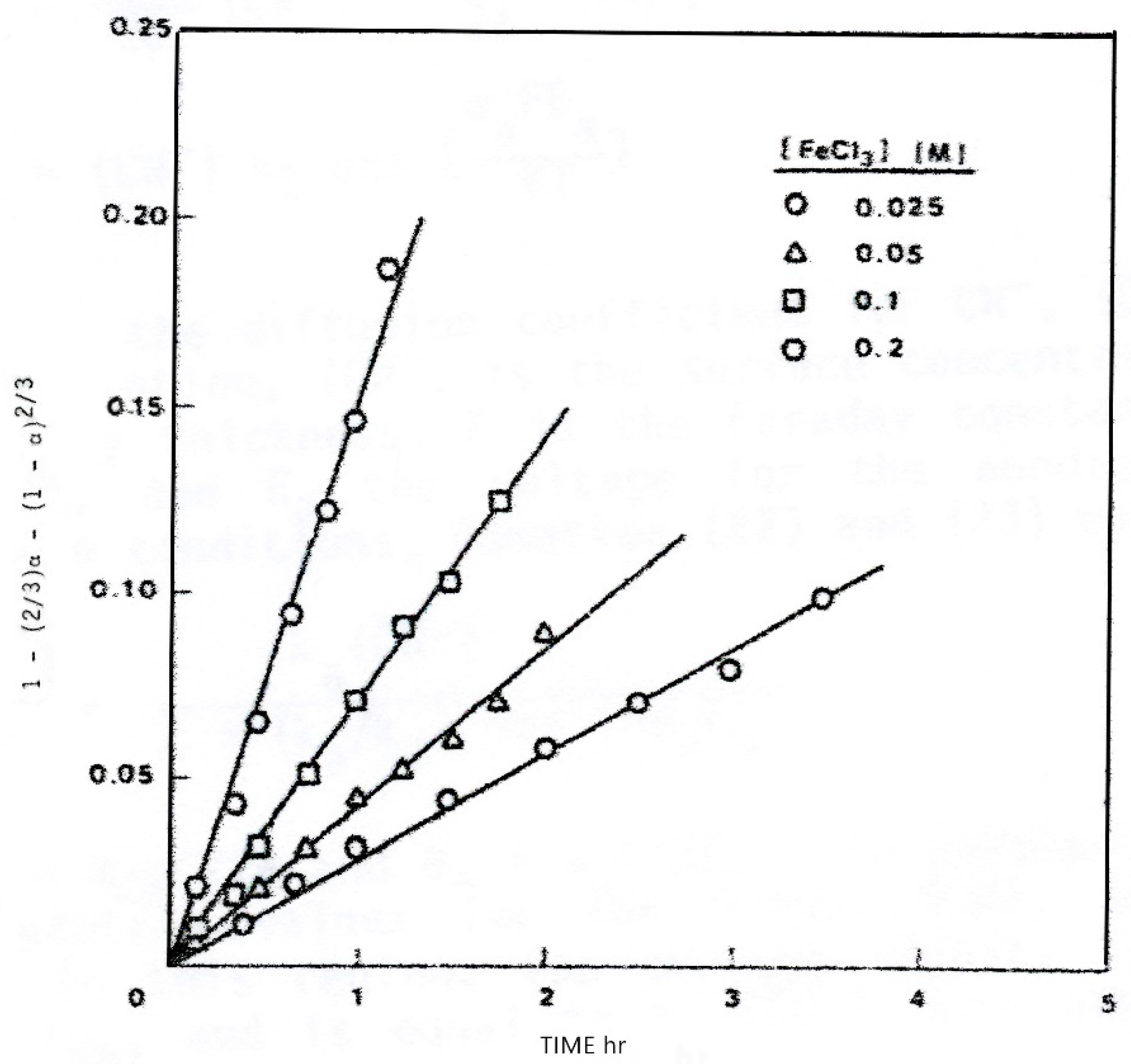
Figure 3.
Kudryk and Kellogg [43] electrochemical data for anodic dissolution of Au and cathodic discharge of oxygen. Dashed curves calculated using mixed-kinetics model.
Figure 3.
Kudryk and Kellogg [43] electrochemical data for anodic dissolution of Au and cathodic discharge of oxygen. Dashed curves calculated using mixed-kinetics model.

Figure 4.
Rate of dissolution of Au at various KCN concentrations for three O2/N2 gas mixtures showing correlation of measured [43] and calculated rates.
Figure 4.
Rate of dissolution of Au at various KCN concentrations for three O2/N2 gas mixtures showing correlation of measured [43] and calculated rates.

Publisher’s Note: MDPI stays neutral with regard to jurisdictional claims in published maps and institutional affiliations. |
© 2022 by the author. Licensee MDPI, Basel, Switzerland. This article is an open access article distributed under the terms and conditions of the Creative Commons Attribution (CC BY) license (https://creativecommons.org/licenses/by/4.0/).
Share and Cite
MDPI and ACS Style
Sequeira, C.A.C. Application of Mixed Potential Theory to Leaching of Mineral Phases. Reactions 2022, 3, 312-328. https://doi.org/10.3390/reactions3020023
AMA Style
Sequeira CAC. Application of Mixed Potential Theory to Leaching of Mineral Phases. Reactions. 2022; 3(2):312-328. https://doi.org/10.3390/reactions3020023
Chicago/Turabian StyleSequeira, César A. C. 2022. "Application of Mixed Potential Theory to Leaching of Mineral Phases" Reactions 3, no. 2: 312-328. https://doi.org/10.3390/reactions3020023