
Modelling Detection Distances to Small Bodies Using Spacecraft Cameras

Interdisciplinary Centre for Reliability, Security, and Trust (SnT), University of Luxembourg, 29 Avenue John F. Kennedy, 1855 Luxembourg, Luxembourg
*
Author to whom correspondence should be addressed.
Modelling 2023, 4(4), 600-610; https://doi.org/10.3390/modelling4040034
Submission received: 25 October 2023
/
Revised: 14 November 2023
/
Accepted: 16 November 2023
/
Published: 17 November 2023
Abstract
:Small bodies in the Solar System are appealing targets for scientific and technological space missions, owing to their diversity in intrinsic and extrinsic properties, besides orbit and other factors. Missions to small bodies pass through the critical onboard object detection phase, where the body’s light becomes visible to the spacecraft camera. The relative line-of-sight to the object is acquired and processed to feed relative guidance and navigation algorithms, therefore steering the spacecraft trajectory towards the target. This work assesses the distance of detection for each small body in the Solar System considering the target radiometric properties, three typical spacecraft camera setups, and the relative observation geometry by virtue of a radiometric model. Several uncertainties and noises are considered in the modelling of the detection process. The detection distances for each known small body are determined for small-, medium-, and large-class spacecraft. This proves useful for early mission design phases, where a waypoint for detection needs to be determined, allowing the shift from an absolute to a relative guidance and navigation phase. The work produces an extensive dataset that is freely accessible and useful for teams working on the design phases of space missions.
1. Introduction
Small bodies such as asteroids and comets are all unique and diverse objects in our Solar System [1]. They are thought to be remnants of the early phases of our Solar System, and therefore might provide insight into the origin of our Solar System and the formation of planets. These objects have also been investigated for the use of space resources through mining activities [2], and most recently defence missions against small body impacts [3] have been demonstrated. Few small bodies have been visited up to now, and more than a million have been catalogued. Each small body is unique in terms of morphology. However, they can still be classified according to the composition classes, which are the types C, S, and M. The type C (chondrite) are the most popular and ancient objects in the Solar System, the type S (stony) are mainly of silicate composition, and the type M (metallic) are mainly constituted by nickel and iron. Several characteristics of small bodies can be inferred by ground-based observations, but detailed and accurate properties can only be acquired by close-proximity measurements [4]. For these reasons, international space agencies have funded several small body missions such as Rosetta [5], Hayabusa 1 [6], Hayabusa 2 [7,8,9], Osiris-Rex [10], Comet Interceptor [11], Lucy [12], Dart [13,14], Hera [15], and others, with the aim of characterising different types of asteroids in the Solar System. More recently, small platform missions such as CubeSats have also been used or proposed for small body missions, such as LiciaCube [16], Juventas [17], Milani [18], NEA-Scout [19,20], M-ARGO [21], LUMIO [22], and others [23,24], also including distributed systems for space exploration [25]. Overall, more and more missions will visit small bodies in the near future.
A critical task for missions to rendezvous with or perform a fly-by of a small body is the target detection by the camera onboard the spacecraft. Small body missions, indeed, traditionally perform spacecraft orbit determination exploiting ground-based radiometric tracking through the ground stations. This provides the means to correct the spacecraft trajectory towards the expected location of the small body. However, this is still an absolute navigation frame, where the relative spacecraft-asteroid geometry is not taken into account. Therefore, to increase the rendezvous or fly-by accuracy with the small body, the target line-of-sight (LoS) needs to be detected onboard, once the target becomes visible. This event marks the transition between the absolute navigation frame to a relative navigation frame with respect to the target. Here, the target line-of-sight is extracted by the onboard camera and used to refine and steer the spacecraft trajectory towards the final approach. Detecting the target from the onboard camera is a radiometric problem where the small body’s luminosity has to be stronger than the noise for detection. The radiometric computation involves several variables coming from the object properties, the camera characteristics, and the spacecraft–target observation geometry given the deep-space orbits. Large-aperture cameras for traditional spacecraft are more powerful than miniaturised cameras for small satellites (e.g., deep-space CubeSats) [26], and the reflected luminosity of small bodies varies according to their size and albedo. Therefore, the target detection problem is a peculiar radiometric assessment, where the detection distance has to be estimated based on the onboard camera properties, the orbit of the spacecraft, and the target properties [27,28,29,30].
This work models the detection of small bodies at a distance by assessing the distance of detection for the full list of known small bodies considering three different camera setups. These are typical of large- to small-class spacecraft, providing a wide spectrum of detection distances for different mission concepts. This contribution is useful for the preliminary mission design phases, where a dedicated waypoint for detection can be exactly located, therefore allowing the acquisition of the object line-of-sight. This work models small body signals and noises by virtue of a radiometric model already accounting for uncertainties involved in the process, producing a large and free-access dataset of detection distances according to different setups.
The paper is structured as follows. Section 2 details the methodology and presents the small body radiometric model, Section 3 performs the detection study evaluation considering the full list of known small bodies and three typical camera setups, and Section 4 provides final remarks and conclusions of this study.
2. Methodology
This section details the modelling and the derivation of the small bodies’ detection distance considering typical spacecraft cameras. The methodology is divided into three steps, as shown in Figure 1. These are (1) the database retrieval, (2) the radiometric modelling, and (3) the detection distance assessment. These steps are detailed in Section 2.1, Section 2.2 and Section 2.3, respectively.
2.1. Database Retrieval
More than a million small bodies have been discovered up to now. The International Astronomical Union’s Minor Planet Center (MPC) is responsible for the designation and orbital computation of the minor planets in the Solar System. This number includes celestial objects such as asteroids, comets, and planetoids, which are generally known as minor planets. The first step for the current study is the retrieval of the small bodies database. The list of orbital elements of the small bodies is retrieved from the Minor Planet Center Orbit Database (MPCORB), which is a collection of the orbital data of minor planets issued by the Minor Planet Center MPC. The inputs from the database are the MPC designation codes for each small body together with the related Keplerian orbital elements on the ecliptic at a reference epoch, designated by the MPC. The absolute magnitude (H) of each small body is retrieved, too, since it will be used for radiometric modelling. The absolute magnitude for a small body is defined as the apparent magnitude of the body as placed at 1 AU from both the Sun and the observer, with an observation at zero phase angle. Then, the visual albedo () of each small body is retrieved from the Asteroid Light Curve Database (LCDB) [31]. Note that the albedo value of known minor bodies spans between 0.05 and 0.40, and the literature value of 0.15 is adopted for unknown bodies. Table 1 summarizes the databases used for this study.
2.2. Radiometric Model
The data collected from the small body databases are the input to the radiometric model building on the Signal-to-Noise ratio (SNR) computation. Then, the SNR of a small body will be used to assess the object detection distance given the geometric and radiometric characteristics of the observations. The SNR is defined as the ratio between the asteroid signal photon counts () and the overall noise involved in the measurement (N) that, following the Poisson statistics, is given by the standard deviation of all the photons coming from both the source and other sources (). Therefore, the SNR is defined as
Note that, when observing a small body in deep space, Equation (1) depends upon the spacecraft-object relative geometry, the camera properties, and the object characteristics. Also, the signal collected from a small body in the visible band depends on the object’s properties, the observation conditions, and the camera’s properties. These considerations are shown in the following.
Figure 2 shows the observation geometry of a small body in the Solar System. The object is placed at a distance to the Sun, and the observer is placed at a distance to the small body. The angle between the Sun–object and object–spacecraft directions is called phase angle and denoted . The signal coming from the small body is actually the portion of the light coming from the Sun and reflected by the small body towards the observer direction. Therefore, the small body signal can be modelled starting from the emissions of the Sun as follows.
Our star emits radiation in all directions according to the Planck’s law:
where is the radiation spectral distribution, the wavelength of emission, h the Planck’s constant, the Boltzmann constant, c the speed of light, and T the equivalent black body temperature of the Sun surface. Therefore, Equation (2) models the radiation emitted by the Sun according to the wavelength. Then, the spectral distribution of the photons emitted by the Sun is obtained diving Equation (2) by the energy of the photon, that is = . Therefore, the spectral distribution of photons emitted from the Sun in all directions () is
Now, the overall amount of photons emitted by the Sun can be obtained by integrating Equation (3) across the wavelengths of interest (between a lower bound and an upper bound ) and multiplying this by the overall dimension of the Sun. The majority of the radiation is in the visible and near-infrared spectrum, and typical navigation cameras onboard satellites are mostly sensitive to these frequency ranges. Therefore, the overall amount of photons emitted by the Sun in all direction in these frequency ranges () is given by
Note that the term models the external surface of the Sun, while the term models the isotropic emission. Now, the radiation coming from the Sun will travel in deep space, losing strength per unit area with the distance (this is commonly known as space loss). Therefore, travelling a distance to the minor body will cause a reduction in the photon counts per unit area. Upon hitting the object, part of the photons will be absorbed and part will be reflected in all directions according to the external surface size and the albedo . The objects with an unknown shape can be modelled as spheres, and, due to the geometry with the Sun, half of the external surface is illuminated by the Sun. Now the observer, placed at a distance and at a phase angle to the small body, will collect the reflected photons with a camera, whose detector area is A, in an integration time t. Also, the camera will introduce losses to the signal due to the quantum efficiency of the detector and the optical lens reduction factor . The quantum efficiency models the ratio of the detected photons over the incoming photons that are hitting the detector, while the optical lens reduction factor models the ratio of the photons that pass through the camera optics over the incoming photons. Eventually, the small body signal acquired by a camera onboard a spacecraft can be modelled as
where and are the wavelength bounds of the spectrum, c is the speed of light, the wavelength, h the Planck constant, the Boltzmann constant, T the black body temperature of the Sun, the Sun radius, D the small body diameter, the small body distance with respect to the Sun, the observer distance with respect to the asteroid, the asteroid phase angle, the optic lens reduction factor, the detector quantum efficiency, A the camera aperture area, and t the exposure time for the signal acquisition. In Equation (5), the terms () model the spherical losses due to distance, the term () models the half-surface reflection of the asteroid assumed to be spherical, and the term models the signal reduction due to the phase angle. Note that few bodies have a known diameter, and therefore they are usually assumed spherical for radiometric simulations. The diameter of an asteroid can be estimated from the absolute magnitude and albedo as [27]
where D is in km. In summary, the signal in Equation (5) consists of the number of photons emitted by the Sun that reach the small body, are reflected in all directions, and are eventually observed by a camera with known parameters and placed at a given observation geometry.
We can now model the noise involved in the detection process. The noise contributions are given from various sources. The signal itself produces a noise, which is known as signal shot noise (). The shot noise, following the Poisson statics, is given by the square root of the source signal itself (). The background of the celestial sky is also producing noise; this is modelled as due to a constant background flux. Therefore, this noise is , where is the background photon flux, commonly equivalent to a flux of magnitude 20 star. Other sources of noise are the dark current shot noise , the read-out noise , the quantisation noise , the photo-response not uniformity noise due to a non-uniformity factor across the detector p in reading the signal, and the fixed pattern noise . All of these parameters can be found on the spacecraft camera datasheets and used in the simulations. Eventually, on top of the modelled noise sources, a noise margin m can be taken into account for robustness against unmodelled noise effects. The values used for the simulations of the SNR for the various cases are given in Section 3.
Eventually, after modelling the minor body signal and the noise sources involved in the detection process, the final SNR is formulated as follows:
where is the number of pixels that delimit the SNR computation. It is worth stressing that small bodies resemble a faint star when imaged from far away; therefore, the SNR modelling here considers delimiting the region of interest (ROI) of the radiometric computation to small windows (e.g., 9 × 9 or 15 × 15 pixels).
2.3. Range of Detection
Small bodies are typically imaged with navigation cameras, and the detection of a small body is achieved when its signal is sufficiently strong with respect to the noise sources. Within an image, the background noise is computed by evaluating the mean intensity of multiple empty regions of interest, and then, the detection of a small body is performed by computing the intensity of the ROI delimiting it and comparing it to the noise sources. The detection limit can be determined when the signal is double the noise (3 dB) or three times the noise (5 dB). In this study, to ensure the robustness of the results, the detection limit is defined at a 5 dB level. Looking at Equations (5) and (7), it is worth stressing that once the small body, the camera parameters, and the integration time have been fixed, the only variables that govern the SNR computations are the geometric ones in terms of distances and angles. In terms of geometry, two extrema points for the minor bodies are the perihelion and the aphelion, respectively. Therefore, this study considers the small bodies to be placed at minimum and maximum distances with respect to the Sun (perihelion and aphelion , respectively) with an observer placed at zero phase angle (). This is to derive the detection distance at these two limiting cases (e.g., when the small body reaches the highest brightness and when it reaches the lowest brightness due to its own orbit). Then, the minor body detection study for varying phase angles can also be addressed starting from these cases. For now, at the zero phase angle, Equation (7) becomes strictly a function of the relative range between the small body and the observer. Therefore, the SNR reads
where
Note that k is a constant value when the small body is at the perihelion () or aphelion (). The goal of the method is now to find the detection range such that . This is achieved by solving the zero-finding problem:
with an iterative Newton method, where is the detection threshold and the iteration step is . The function is continuous and monotonic, and has a single zero cross value, since the negative values are not allowed. Therefore, the final detection distance can be found starting from a guess value and then iterating with the correction at each step.
3. Assessment
This Section deals with the determination of the detection distance to the small bodies given the object properties, the camera characteristics, and the observation geometry. The camera properties are detailed in Section 3.1, the creation of the dataset of detection distances is explained in Section 3.2, and remarks on this study are given in Section 3.3.
3.1. Camera Properties
The distance of detection for the full list of small bodies is evaluated for three different camera sets, similar to the ones used for three categories of spacecraft. These are: (1) a low performance camera, LP; (2) a medium performance camera, MP; and (3) a high performance camera, HP. The different camera characteristics are detailed in Table 2. It is worth mentioning that the exposure time is kept constant among the three setups for a fair comparison of results, while the camera performances increase from the LP to the HP setups and the noise contributions decrease from the LP to the HP setups. Also, it is important to note that the noise margin has been taken into account to consider unmodelled effects in the noise sources.
Note that the LP camera aperture and characteristics resemble the ones typical of deep-space CubeSats [21], the MP characteristics resemble the ones of traditional missions to small bodies (e.g., the Rosetta NavCam [28]), and the HP camera characteristics resemble the ones of the state-of-the-art camera for far distant observation (e.g., the LORRI camera [29]). In this way, the range of detection of each small body can be assessed for different categories of spacecraft cameras, covering a wide spectrum of space mission classes.
3.2. Dataset Creation
The assessment of the detection distance is detailed in the following. The orbital and radiometric properties of each small body in the Minor Planet Center database are retrieved. Then, according to the three camera setups in Table 2 and to the location of each small body (both at aphelion and perihelion), Equation (10) is solved. Therefore, for each small body, six detection distances are produced under the following combinations, each at zero phase angle:
- -
- Case (1): small body at perihelion, HP camera;
- -
- Case (2): small body at aphelion, HP camera;
- -
- Case (3): small body at perihelion, MP camera;
- -
- Case (4): small body at aphelion, MP camera;
- -
- Case (5): small body at perihelion, LP camera;
- -
- Case (6): small body at aphelion, LP camera.
The SNR values (Equation (8)) for six sample objects (Astraea, Virginia, Hygiea, Psyche, Lutetia, and Kallisto) are shown in Figure 3. The SNR values are computed for varying observer distances in cases (1) to (6). The dashed horizontal line delimits the 5 dB threshold, which corresponds to the body detection distance under the case considered. Note that the solution to Equation (10) for each case is shown as a dot in Figure 3a–f.
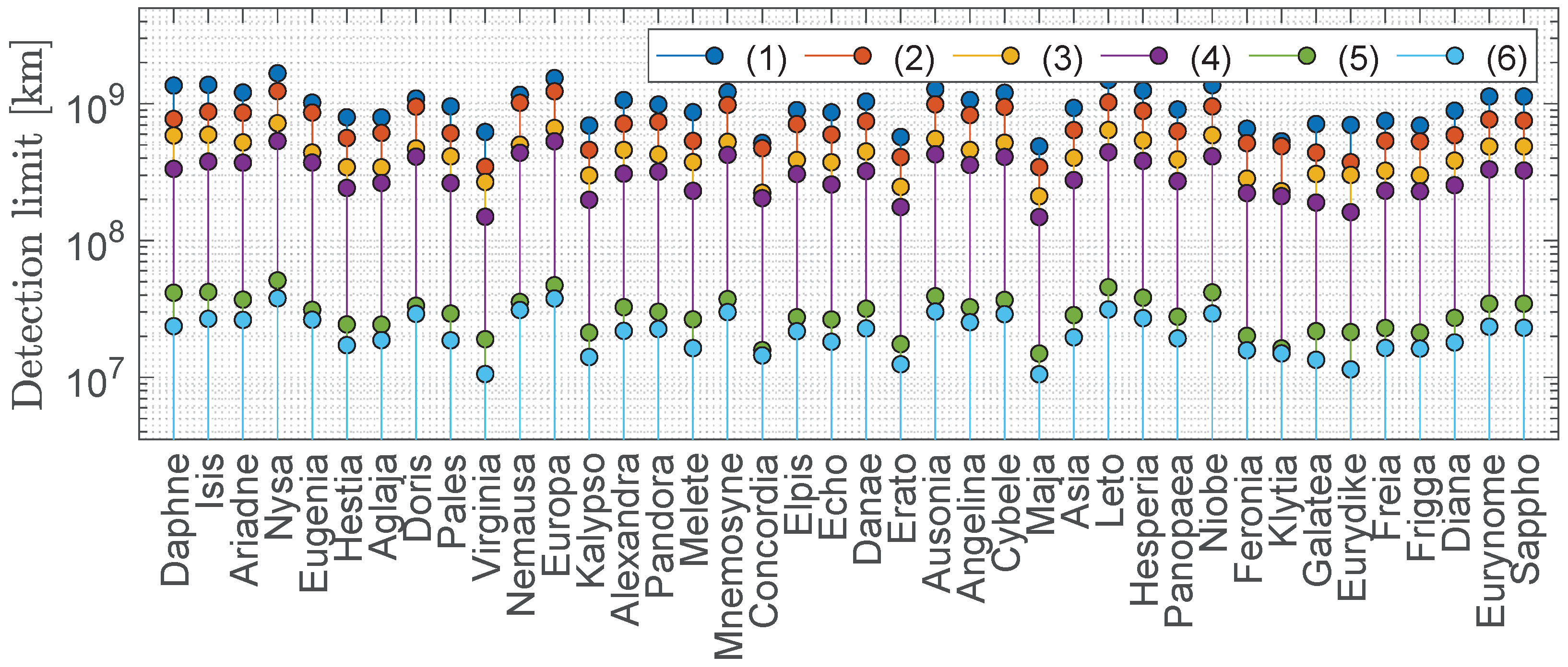
Figure 4 shows the detection limit considering cases 1 to 6 for the first 80 catalogued small bodies. It is immediate to appreciate the detection limit excursion between the small body perihelion and aphelion conditions (e.g, cases 1 and 2, or 3 and 4, or 5 and 6 along the same vertical line). Note also that each of the vertical lines in Figure 4 retraces the horizontal line in Figure 3 for each small body. Therefore, given a small body and a spacecraft camera, the object detection distance is determined at the extreme points of the object orbit (that is, at aphelion and perihelion), considering a zero phase angle observation. Also, Equations (7) and (10) have been solved under varying phase angles to complete the study of detection distances, therefore creating a complete dataset. The dataset of detection distances based on the three camera setups and the full list of small bodies has been created and made freely accessible. The dataset can be found in [32] together with the instructions for reading the data. The dataset proves useful for mission design phases, where a waypoint for detection needs to be placed in order to transition from absolute to relative guidance and navigation phases.
3.3. Remarks
The dataset of detection distances to small bodies has considered the radiometric parameters of small bodies known at the date of publication. We emphasise that these might be updated over time, resulting in updates in the detection distances. Also, the albedo of the vast majority of small bodies is unknown because they have not been visited yet, and the literature value of 0.15 has been adopted for unknown objects. This work has considered observations at phase angles spanning from 0 to 90 degrees, because the detection phase typically happens at these phase angles. At higher phase angles there would be other effects coming from the Sun [33], e.g., the straylight effect. A study for higher phase angles is a direction for future studies. Regarding the camera performances, the higher-order effects in the noise have been lumped into a noise margin parameter, spanning from 10% to 20% of the overall noise. In addition, the detection distance threshold has been set at a 5 dB level, but detection can occur even at a lower threshold. Therefore, the noise contribution to the detection is slightly conservative in this paper.
The published dataset will facilitate future deep-space missions to small bodies. During the preliminary design phases of a space mission, once the target asteroid and spacecraft platform have been defined, the target detection distance can be recovered for different conditions.
4. Conclusions
Out of more than a million, just few minor bodies have been visited by spacecraft missions. Deep-space missions to small bodies in the Solar System are becoming more popular owing to the peculiarity of these target objects. These missions pass through the distant detection phase of the target, where the object’s line-of-sight relative to the spacecraft is tracked in time. This marks the transition from an absolute to a relative guidance and navigation phase, where the spacecraft trajectory is steered with respect to the line-of-sight with the target to achieve a fly-by or rendezvous. This work has modelled and simulated the far-distant detection study for the full list of known small bodies considering the target radiometric properties, three different camera setups typical of different classes of spacecraft missions, and the relative observation geometry by virtue of a radiometric model. The work has produced a large open dataset containing the detection distances for each known small body, which is freely accessible for teams working on design phases of space missions. This is useful to correctly locate a way point for target detection along the deep-space trajectory.
Author Contributions
Conceptualization, V.F.; methodology, V.F.; software, V.F.; validation, V.F.; formal analysis, V.F.; investigation, V.F.; resources, V.F.; data curation, V.F.; writing—original draft preparation, V.F.; writing—review and editing, A.M.H.; visualization, V.F.; supervision, V.F.; project administration, V.F.; funding acquisition, A.M.H. All authors have read and agreed to the published version of the manuscript.
Funding
This research received no external funding.
Data Availability Statement
The data presented in this study are openly available in Zenodo at https://doi.org/10.5281/zenodo.8054615 (accessed on 7 June 2023).
Acknowledgments
This research has made use of data and/or services provided by the International Astronomical Union’s Minor Planet Center.
Conflicts of Interest
The authors declare no conflict of interest.
References
- Yeomans, D. Small bodies of the solar system. Nature 2000, 404, 829–832. [Google Scholar] [CrossRef] [PubMed]
- Hein, A.M.; Matheson, R.; Fries, D. A techno-economic analysis of asteroid mining. Acta Astronaut. 2020, 168, 104–115. [Google Scholar] [CrossRef]
- Rivkin, A.S.; Cheng, A.F. Planetary defense with the Double Asteroid Redirection Test (DART) mission and prospects. Nat. Commun. 2023, 14, 1003. [Google Scholar] [CrossRef] [PubMed]
- Scheeres, D.J.; McMahon, J.W.; French, A.S.; Brack, D.N.; Chesley, S.R.; Farnocchia, D.; Takahashi, Y.; Leonard, J.M.; Geeraert, J.; Page, B.; et al. The dynamic geophysical environment of (101955) Bennu based on OSIRIS-REx measurements. Nat. Astron. 2019, 3, 352–361. [Google Scholar] [CrossRef]
- Glassmeier, K.H.; Boehnhardt, H.; Koschny, D.; Kührt, E.; Richter, I. The Rosetta mission: Flying towards the origin of the solar system. Space Sci. Rev. 2007, 128, 1–21. [Google Scholar] [CrossRef]
- Yoshikawa, M.; Kawaguchi, J.; Fujiwara, A.; Tsuchiyama, A. Hayabusa sample return mission. Asteroids IV 2015, 1, 397–418. [Google Scholar] [CrossRef]
- Watanabe, S.i.; Tsuda, Y.; Yoshikawa, M.; Tanaka, S.; Saiki, T.; Nakazawa, S. Hayabusa2 mission overview. Space Sci. Rev. 2017, 208, 3–16. [Google Scholar] [CrossRef]
- Kawaguchi, J.; Fujiwara, A.; Uesugi, T. Hayabusa—Its technology and science accomplishment summary and Hayabusa-2. Acta Astronaut. 2008, 62, 639–647. [Google Scholar] [CrossRef]
- Tsuda, Y.; Yoshikawa, M.; Abe, M.; Minamino, H.; Nakazawa, S. System design of the Hayabusa 2—Asteroid sample return mission to 1999 JU3. Acta Astronaut. 2013, 91, 356–362. [Google Scholar] [CrossRef]
- Lauretta, D.; Balram-Knutson, S.; Beshore, E.; Boynton, W.; d’Aubigny, C.D.; DellaGiustina, D.; Enos, H.; Golish, D.; Hergenrother, C.; Howell, E.; et al. OSIRIS-REx: Sample return from asteroid (101955) Bennu. Space Sci. Rev. 2017, 212, 925–984. [Google Scholar] [CrossRef]
- Snodgrass, C.; Jones, G.H. The European Space Agency’s Comet Interceptor lies in wait. Nat. Commun. 2019, 10, 5418. [Google Scholar] [CrossRef] [PubMed]
- Levison, H.F.; Olkin, C.B.; Noll, K.S.; Marchi, S.; Bell, J.F., III; Bierhaus, E.; Binzel, R.; Bottke, W.; Britt, D.; Brown, M.; et al. Lucy Mission to the Trojan Asteroids: Science Goals. Planet. Sci. J. 2021, 2, 171. [Google Scholar] [CrossRef]
- Atchison, J.A.; Ozimek, M.T.; Kantsiper, B.L.; Cheng, A.F. Trajectory options for the DART mission. Acta Astronaut. 2016, 123, 330–339. [Google Scholar] [CrossRef]
- Rivkin, A.S.; Chabot, N.L.; Stickle, A.M.; Thomas, C.A.; Richardson, D.C.; Barnouin, O.; Fahnestock, E.G.; Ernst, C.M.; Cheng, A.F.; Chesley, S.; et al. The Double Asteroid Redirection Test (DART): Planetary Defense Investigations and Requirements. Planet. Sci. J. 2021, 2, 173. [Google Scholar] [CrossRef]
- Michel, P.; Küppers, M.; Bagatin, A.C.; Carry, B.; Charnoz, S.; de Leon, J.; Fitzsimmons, A.; Gordo, P.; Green, S.F.; Hérique, A.; et al. The ESA Hera Mission: Detailed Characterization of the DART Impact Outcome and of the Binary Asteroid (65803) Didymos. Planet. Sci. J. 2022, 3, 160. [Google Scholar] [CrossRef]
- Dotto, E.; Della Corte, V.; Amoroso, M.; Bertini, I.; Brucato, J.; Capannolo, A.; Cotugno, B.; Cremonese, G.; Di Tana, V.; Gai, I.; et al. LICIACube-the Light Italian Cubesat for Imaging of Asteroids in support of the NASA DART mission towards asteroid (65803) Didymos. Planet. Space Sci. 2021, 199, 105185. [Google Scholar] [CrossRef]
- Goldberg, H.R.; Karatekin, Ö.; Ritter, B.; Herique, A.; Tortora, P.; Prioroc, C.; Gutierrez, B.G.; Martino, P.; Carnelli, I. The Juventas CubeSat in Support of ESA’s Hera Mission to the Asteroid Didymos. In Proceedings of the Small Satellite Conference, Logan, UT, USA, 3–8 August 2019; pp. 1–7. [Google Scholar]
- Pugliatti, M.; Piccolo, F.; Rizza, A.; Franzese, V.; Topputo, F. The vision-based guidance, navigation, and control system of Hera’s Milani Cubesat. Acta Astronaut. 2023, 210, 14–28. [Google Scholar] [CrossRef]
- Lockett, T.R.; Castillo-Rogez, J.; Johnson, L.; Matus, J.; Lightholder, J.; Marinan, A.; Few, A. Near-Earth Asteroid Scout Flight Mission. IEEE Aerosp. Electron. Syst. Mag. 2020, 35, 20–29. [Google Scholar] [CrossRef]
- Pezent, J.; Sood, R.; Heaton, A. High-fidelity contingency trajectory design and analysis for NASA’s near-earth asteroid (NEA) Scout solar sail Mission. Acta Astronaut. 2019, 159, 385–396. [Google Scholar] [CrossRef]
- Franzese, V.; Topputo, F.; Ankersen, F.; Walker, R. Deep-space optical navigation for M–ARGO mission. J. Astronaut. Sci. 2021, 68, 1034–1055. [Google Scholar] [CrossRef]
- Merisio, G.; Topputo, F. Present-day model of lunar meteoroids and their impact flashes for LUMIO mission. Icarus 2023, 389, 115180. [Google Scholar] [CrossRef]
- Casini, S.; Fodde, I.; Monna, B.; Cervone, A.; Gill, E. Novel 3U Stand-Alone CubeSat Architecture for Autonomous Near Earth Asteroid Fly-By. Aerospace 2021, 8, 9. [Google Scholar] [CrossRef]
- Lombardo, M.; Zannoni, M.; Gai, I.; Gomez Casajus, L.; Gramigna, E.; Manghi, R.L.; Tortora, P.; Di Tana, V.; Cotugno, B.; Simonetti, S.; et al. Design and Analysis of the Cis-Lunar Navigation for the ArgoMoon CubeSat Mission. Aerospace 2022, 9, 659. [Google Scholar] [CrossRef]
- Schilling, K. Perspectives for miniaturized, distributed, networked cooperating systems for space exploration. Robot. Auton. Syst. 2017, 90, 118–124. [Google Scholar] [CrossRef]
- Franzese, V.; Topputo, F. Celestial Bodies Far-Range Detection with Deep-Space CubeSats. Sensors 2023, 23, 4544. [Google Scholar] [CrossRef]
- Seidelmann, P.K. Explanatory Supplement to the Astronomical Almanac; University Science Books: Melville, NY, USA, 1992. [Google Scholar]
- Morley, T.; Budnik, F. Rosetta Navigation for the Fly-by of Asteroid 2867 Šteins. In Proceedings of the 21st International Symposium on Space Flight Dynamics-21st ISSFD, Toulouse, France, 28 September–2 October 2009; pp. 1–15. [Google Scholar]
- Cheng, A.F.; Weaver, H.; Conard, S.; Morgan, M.; Barnouin-Jha, O.; Boldt, J.; Cooper, K.; Darlington, E.; Grey, M.; Hayes, J.; et al. Long-Range Reconnaissance Imager on New Horizons. In New Horizons: Reconnaissance of the Pluto-Charon System and the Kuiper Belt; Springer: New York, NY, USA, 2009; pp. 189–215. [Google Scholar] [CrossRef]
- Rizk, B.; Drouet d’Aubigny, C.; Golish, D.; Fellows, C.; Merrill, C.; Smith, P.; Walker, M.; Hendershot, J.; Hancock, J.; Bailey, S.; et al. OCAMS: The OSIRIS-REx camera suite. Space Sci. Rev. 2018, 214, 26. [Google Scholar] [CrossRef]
- Warner, B.D.; Harris, A.W.; Pravec, P. The asteroid lightcurve database. Icarus 2009, 202, 134–146. [Google Scholar] [CrossRef]
- Franzese, V.; Hein, A.M. Dataset of Detection Distances to Small Bodies Using Spacecraft Cameras; Zenodo: Geneve, Switzerland, 2023. [Google Scholar] [CrossRef]
- McBrayer, K.T.; Chai, P.; Judd, E. Communication Delays, Disruptions, and Blackouts for Crewed Mars Missions. In ASCEND 2022; AIAA: Reston, VA, USA, 2022; p. 4239. [Google Scholar]
Figure 1.
Flowchart of small bodies detection range determination.
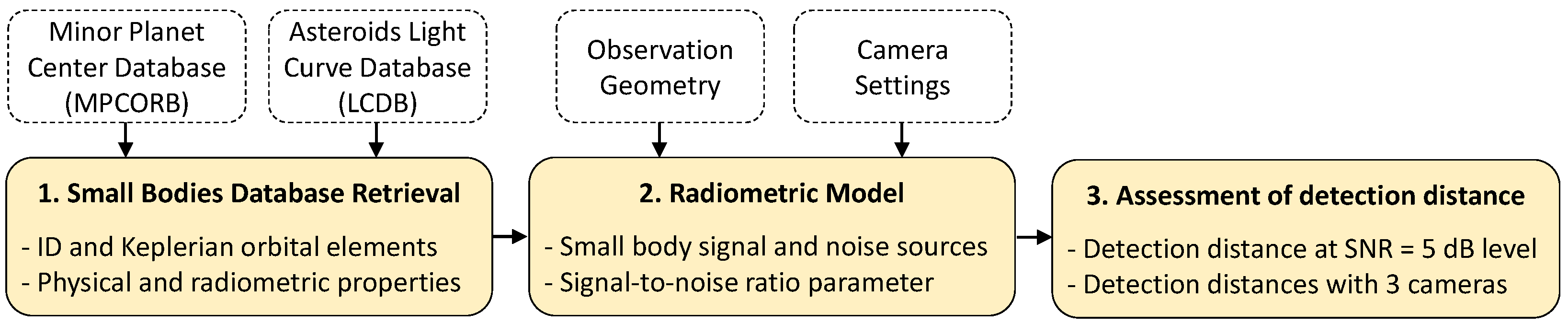
Figure 2.
Observation geometry of a small body, where is the Sun–small body distance, is the small body–spacecraft distance, and is the small body phase angle as seen from the spacecraft.
Figure 2.
Observation geometry of a small body, where is the Sun–small body distance, is the small body–spacecraft distance, and is the small body phase angle as seen from the spacecraft.

Figure 3.
SNR values for six sample bodies: (a) Astraea; (b) Virginia; (c) Hygiea; (d) Psyche; (e) Lutetia; (f) Kallisto; under the following cases and at zero phase angle: (1) small body at perihelion, HP camera; (2) small body at aphelion, HP camera; (3) small body at perihelion, MP camera; (4) small body at aphelion, MP camera; (5) small body at perihelion, LP camera; (6) small body at aphelion, LP camera. The horizontal dashed line corresponds to the 5 dB detection threshold.


Figure 4.
Detection limit for the first 80 small bodies listed in the MPC at zero phase angle: (1) small body at perihelion, HP camera; (2) small body at aphelion, HP camera; (3) small body at perihelion, MP camera; (4) small body at aphelion, MP camera; (5) small body at perihelion, LP camera; (6) small body at aphelion, LP camera.


Table 1.
List of input databases.
| Characteristic | Database |
|---|---|
| Small body orbital elements | MPCORB |
| Small body absolute magnitude | MPCORB |
| Small body albedo | LCDB |
Table 2.
LP, MP, and HP cameras settings.
| Parameter | Parameter | Unit | LP | MP | HP |
|---|---|---|---|---|---|
| Entrance pupil diameter | m | 0.01 | 0.10 | 0.20 | |
| Exposure time | t | s | 1 | 1 | 1 |
| Optical lens factor | [-] | 0.60 | 0.70 | 0.75 | |
| Quantum efficiency | [-] | 0.60 | 0.70 | 0.75 | |
| Pixel window | pix | 15 × 15 | 15 × 15 | 15 × 15 | |
| Read-out noise | e | 200 | 100 | 80 | |
| Dark current noise | e | 200 | 100 | 80 | |
| Quantisation noise | e | 30 | 20 | 10 | |
| Fixed-pattern noise | e | 200 | 100 | 80 | |
| Photo-response factor | p | % | 2.0 | 1.5 | 1.0 |
| Noise margin | m | % | 20 | 15 | 10 |
Disclaimer/Publisher’s Note: The statements, opinions and data contained in all publications are solely those of the individual author(s) and contributor(s) and not of MDPI and/or the editor(s). MDPI and/or the editor(s) disclaim responsibility for any injury to people or property resulting from any ideas, methods, instructions or products referred to in the content. |
© 2023 by the authors. Licensee MDPI, Basel, Switzerland. This article is an open access article distributed under the terms and conditions of the Creative Commons Attribution (CC BY) license (https://creativecommons.org/licenses/by/4.0/).
Share and Cite
MDPI and ACS Style
Franzese, V.; Hein, A.M. Modelling Detection Distances to Small Bodies Using Spacecraft Cameras. Modelling 2023, 4, 600-610. https://doi.org/10.3390/modelling4040034
AMA Style
Franzese V, Hein AM. Modelling Detection Distances to Small Bodies Using Spacecraft Cameras. Modelling. 2023; 4(4):600-610. https://doi.org/10.3390/modelling4040034
Chicago/Turabian StyleFranzese, Vittorio, and Andreas Makoto Hein. 2023. "Modelling Detection Distances to Small Bodies Using Spacecraft Cameras" Modelling 4, no. 4: 600-610. https://doi.org/10.3390/modelling4040034