
Agitation of Viscoplastic Fluid in a Rotating Vessel Using Close Clearance Agitators


Center for Mechanical and Aerospace Science and Technologies (C-MAST), University of Beira Interior, 6201-001 Covilhã, Portugal
Eng 2023, 4(4), 2525-2541; https://doi.org/10.3390/eng4040144
Submission received: 4 September 2023
/
Revised: 1 October 2023
/
Accepted: 6 October 2023
/
Published: 8 October 2023
Abstract
:Technological advancements have continued to progress in all fields, achieving remarkable feats. Additionally, productivity is increasing across the board as a result of strong economic expansion, which has encouraged changes in people’s way of life, such as the increasing use of pharmaceutical products, cosmetics, detergents, and food products. A hydrothermal study is required in these areas to optimize the design of the stirring system. The aim of the current work is to investigate the hydrodynamics and thermodynamics of a mechanical agitation system with a non-Newtonian fluid of the Bingham–Bercovier type in a cylindrical vessel with three blade configurations. Our research is specifically directed towards mechanically agitated systems utilizing close clearance stirrers, particularly focusing on the anchor, gate and two-bladed impellers, within cylindrical tanks that possess flat bottoms without baffles. The results show that the anchor impeller, with its broad blades and low-shear characteristics, is more suited for breaking down yield stress and inducing flow in these fluids, which creates a wide flow pattern that effectively overcomes yield stress. However, the addition of vertical arms to transform it into a gate impeller promotes mixing, heat transfer and thermal efficiency with a small energy cost compared to an anchor impeller against the two-bladed impeller.
1. Introduction
Efficient mixing is essential for attaining the full homogenization of process substances within a vessel, ensuring that all reactive components can interact harmoniously to produce the desired product. Moreover, the level of homogeneity in a system significantly impacts heat transfer. An ideal system can uphold a consistent temperature across the entire tank volume and promptly respond to changes.
One significant category of non-Newtonian fluids is viscoplastic fluids [1], which are often used in chemical engineering in the pharmaceutical, food, paint, polymer and cosmetic sectors. These fluids exhibit unique behavior, flowing only when subjected to shear stress exceeding a critical value [2], which creates dead zones where the fluid is less agitated and affects the mixing efficiency; in addition, more difficulties are encountered due to complex rheology proprieties when dealing with these types of highly viscous fluids, wherein they exhibit a range of possible behaviors, which still remain a challenge.
In the laminar mixing of high viscosity fluids, close clearance impellers are suitable among the several types of impellers that are accessible in industries [3,4]. Several studies have explored the characteristics of these types of impellers. Bertrand et al. [5] carried out a 3D numerical investigation focused on the mixing of non-Newtonian fluids under laminar flow conditions, employing an anchor impeller agitator. Hami et al. [6] revealed that an anchor impeller with a 45° blade inclination consumes significantly more power compared to a classical anchor agitator. Mihailova et al. [7] delved into the performance of merged anchor-helical impellers and highlighted the pivotal role of impeller height in overall mixing system performance. Ameur et al. [8] innovatively combined an anchor impeller with a Scaba 6SRGT turbine for mixing shear-thinning fluids, achieving notable improvements in cavern size, particularly near the impeller axis. Mebarki et al. [9] conducted a numerical exploration of a novel round-shaped anchor impeller design for mixing yield stress fluids. Their results presented several advantages over the standard anchor impeller, including improved flow field patterns and reduced energy consumption costs. Prajapati and Ein-Mozaffari [10] investigated the mixing behavior of viscoplastic fluids using anchor impellers. Their study determined the optimal values for the stirrer clearance-to-vessel diameter and the stirrer width-to-vessel diameter ratios as 0.079 and 0.102, respectively. They also found that the four-bladed anchor impeller outperformed the two-bladed variant in terms of mixing efficiency.
Numerous research efforts have employed a combination of experimental and computational approaches to improve the efficiency [11] of hydrodynamic configurations and address operational constraints. Several researchers have made valuable contributions on the thermal behavior and fluid flow within agitated tanks through a range of studies documented in the literature [12]. Among them, Anne-Archard et al. [13] explored the distributions of shear rates and their correlation to power consumption during the mixing of power-law fluids using helical and anchor impellers. They developed a Metzner–Otto correlation applicable to power-law fluids, including Bingham, Herschel–Bulkley, and Casson fluids. Foukrach et al. [14] investigated the influence of various agitator types on turbulent flows within stirred tanks, both with and without baffles. Their research revealed that the agitator DTBT effectively reduced the vortex size at specific impeller angles. Korib et al. [15] conducted a numerical simulation to investigate the fluid flow and heat transfer around a rotating circular cylinder at low Reynolds numbers. Their study revealed that as the rotational rate increased, the mean Nusselt number decreased. Ameur et al. [16] employed a modified impeller configuration comprising a combination of a curved blade turbine and a standard anchor impeller. They investigated the impact of geometric design, anchor curvature, and shear zone on energy consumption. The same authors proposed a modification to the classical anchor impeller design in [17] by curving the upper vertical arms of the blade structure to prevent blade deformation and enhance impeller performance. Furthermore, they investigated the flow energy efficiency of double helical ribbon, anchor, gate and Maxblend impellers for stirring shear-thinning fluids in cylindrical tanks in [18]. They found that the Maxblend impeller exhibited the best mixing quality and less energy consumption. Kamla et al. [19] conducted a comprehensive comparison of anchor impellers with blades of different shapes, including rectangular, octagonal, and circular designs. Their findings indicated that the octagonal blade shape provided the broadest well-stirred region. However, the circular blade shape demonstrated the lowest power input requirements. Benmoussa et al. [20] explored the hydrodynamic properties of a mixing system with an anchor agitator using a viscoplastic fluid model by Bercovier and Engelman. Their findings highlighted the impact of different rheological parameters on the flow pattern, heat exchange and power consumption. Later, Komoda et al. [21] conducted a numerical investigation on the effect of various geometric parameters of the anchor impeller on fluid mixing characteristics, with a specific focus on achieving uniform fluid spreading. Following this, the authors conducted experimental observations of streaklines in the horizontal cross-section to validate the optimized anchor impeller design. In another study, conducted by Kada et al. [22], a three-dimensional numerical investigation was carried out on a Bingham–Papanastasiou fluid using different geometric designs and inclination angles of anchor blades within a stirred vessel. The findings revealed that the anchor impeller with a 60° inclination exhibited the most efficient acceleration of flow within the stirred system. Coaxial mixers equipped with close clearance impellers have shown significant interest due to their potential for intensification. Bao et al. [23] tested four coaxial mixer configurations, each pairing either a CBY or Pfaudler impeller as the inner component with an outer component of either an anchor or helical ribbon (HR). Pakzad et al. [24] evaluated the performance of anchor coaxial mixers in agitating yield-pseudoplastic fluids in terms of mixing time and specific power consumption. Kazemzadeh and collaborators [25,26] conducted a systematic investigation on the impact of rheological properties on the power consumption and mixing time of coaxial mixers. Recently, Shiue et al. [27] conducted a comparative study of three coaxial mixers featuring different inner elements: a Cowles turbine, a four-pitched blade turbine, and a three-blade propeller impeller, in conjunction with an anchor impeller as the outer element. This investigation encompassed laminar, transition, and turbulent flow conditions. Their findings revealed that the combination of a four-pitched blade turbine and an anchor impeller achieved the shortest mixing time while consuming less power. Table 1 provides a concise summary of recent studies exploring the mixing of non-Newtonian fluids using a variety of close clearance impellers.
Although heat transfer within stirred vessels plays a crucial role in improving the mixture quality and expediting chemical reactions, it is important to highlight the limited research dedicated to exploring the thermal characteristics of viscoplastic fluids in stirred tanks. Thus, this paper’s primary aim is to assess the energy efficiency and thermal performance of different impeller configurations employed in agitating yield stress fluids. The study places particular emphasis on the anchor, gate, and two-bladed impellers.
The remaining sections of this paper are organized as follows: Section 2 provides an overview of the numerical formulation, encompassing the governing equations, fluid behavior, and the mechanical agitation systems. Section 3 thoroughly examines and discusses the simulation results. Section 4 presents the conclusion.
2. Numerical Modeling and Computational Settings
2.1. Mechanical Agitation System
Figure 1 depicts the geometries of the three stirring systems. A cylindrical vessel with a flat bottom and no baffles, having a diameter Dv = 300 mm and a height Hv/Dv = 1, was equipped with an impeller. Three type of impellers were used: anchor (Figure 1a), gate (Figure 1b) and two-bladed (Figure 1c), with a diameter d = 288 mm, which rotated around a shaft of diameter da/Dv = 0.023. The blade of the impeller had a dimension of L/Dv = 0.074 and a thickness of e/Dv = 0.02, and geometrical details are provided in Table 2.
The planar impellers generated a tangential flow, in which the axial velocity was negligible in comparison to the tangential one; furthermore, the slight dependency of the flow field and temperature on the vertical axis only spread in the horizontal plane, as was conducted in many studies [28,29]. In addition, the symmetrical design of the flat-bottomed vessel made the fluid sweep symmetrically over the vessel’s horizontal levels. Therefore, the simulation was conducted in two dimensions.
2.2. Governing Equations
The fluid is non-Newtonian incompressible and the flow was considered laminar. Neglecting the areas near the bottom of the tank and the free surface of the liquid, we assumed that all horizontal planes were identical.
The equations governing the flow are represented by mass conservation, filtered momentum and energy equations.
is the thermal diffusivity, defined by:
where , λ and denote the specific heat, the thermal conductivity and the fluid density, respectively.
2.3. Fluid Comportment
The fluid rheology is described using a regularized version of the Bingham model proposed by Bercovier and Engelman [30], which is characterized by the existence of a minimum value () of yield stress or flow threshold, in which there is no flow below. It is provided by
where is the infinite shear rate viscosity, refers to the fluid’s shear stress, is the yield stress and is a regularization parameter.
and denote the tensor of deformation and the stress tensor, respectively, and are defined by
denotes the second invariant of the strain rate tensor obtained using
Two zones define the flow domain for a yield stress fluid. The first zone is when , and the material acts rigidly, while in the material flows with an apparent viscosity , which is given by
The dimensionless parameters used are
where denote the radial and tangential velocities, is the rotational speed and is the vessel diameter.
The dimensionless numbers are presented below [13]:
- Reynolds number:
- Bingham number:
- Nusselt number:
- Power consumption:
2.4. Solver Settings
The numerical simulation was carried out through ANSYS Fluent 16 software based on the finite-volume method and Navier–Stokes equations; the fluid model was coded and loaded into the solver using a user-defined function (UDF) framework [31,32]. A second order upwind scheme was used to solve the discrete equations with coupling pressure-velocity and the SIMPLE algorithm.
For boundary conditions, a rotating reference frame was selected rather than a fixed reference frame to avoid the periodic flow caused by the rotation of the impeller. In the rotating reference frame (RRF), the stirrer was held stationary, while the vessel rotated with the same angular velocity as the rotating frame in the opposite direction, considering centrifugal and Coriolis accelerations. This technique was used and proved by many authors, namely Hami et al. [5], Mebarki et al. [8], Anne-Archard et al. [12], Marouche et al. [33], and Rahmani et al. [34]. Afterwards, the results were then expressed in a fixed frame in a post-processing stage. The residuals for all variables were set to 10−6 in order to satisfy the convergence criterion.
Figure 2 illustrates the two-dimensional computational domain and boundary conditions. The selected mesh for the computational domain was triangular and was refined near the impeller edge.
The boundary conditions for velocity were defined as follows:
- On the impeller ;
- On the vessel .
Temperature conditions were applied to the vessel wall and insulate on the impeller.
- On the impeller ;
- On the vessel .
3. Results and Discussion
3.1. Grid Independency and Numerical Validation
Three unstructured triangular grid resolutions were employed to determine the optimal mesh for accurate calculations and to obtain correct results. These resolutions, referred to as mesh1, mesh2 and mesh3, had varying numbers of cells—specifically, 26,044, 40,610 and 59,288 cells, respectively.
The effects of these three meshes are depicted in Figure 3. The tangential velocity on the median plane of mesh2 and mesh3 exhibited negligible differences, as can be observed. Therefore, our simulation was conducted using mesh2, which comprised a total of 40,610 cells in the overall computational domain (Figure 2).
At first, it was necessary to validate our numerical model using the available previous data. Therefore, we used the same rheological and geometrical characterization of a stirred system as chosen by Marouche et al. [33] and Rahmani et al. [34], with the working fluid being Bingham. As shown in Figure 4, the computed results exhibited good agreement.
3.2. Effect of Inertia
Assessing the mixing performance in a stirred system relies significantly on the flow pattern, which is influenced by both the rotational speed of the impeller and its design. Figure 5 shows the stream function results comparison obtained for the three impellers as functions of the Reynolds number for = 1 Pa and = 0.01.
In Figure 5a, for the anchor impeller, a recirculation zone exists within the streamlines, characterized by closed loop patterns. This zone is symmetric with respect to the bisector for low Reynolds numbers. As the Reynolds number increases, this zone shifts towards the leading edges of the impeller, showcasing the prevalence of inertial forces over viscosity forces.
In Figure 5b, for the gate impeller, three distinct regions can be identified. One region experiences low shear near the first blade, while another region encounters higher shear near the second blade. The third region represents the remaining fluid, which we will refer to as the solid region.
For the two-bladed impeller (Figure 5c), the area near the blade subject to significant shear becomes prominent in contrast to the rest of the tank, thereby constituting the solid region.
It can be noticed that close to the blades, a deviation in the streamlines is observable. This deviation becomes more pronounced as the Reynolds number increases, indicating heightened shear forces experienced by the fluid in this region. From the external edge of the blade to the tank wall, the streamlines remain roughly parallel to the wall, implying that the flow in this area assumes a tangential nature.
Figure 6 and Figure 7 illustrate the variation in the tangential velocity on the blade and its extension and on the median plane, respectively, for the three impellers as a function of the radial position for Re 13.8 and Re = 416 with . It is evident in Figure 6 that the tangential flow structures were nearly identical across all impellers. The tangential velocity reached its maximum, which is 0.96, at the tip of the impeller blades and gradually decreased to zero along the tank wall. It can be observed that the tangential component of velocity was negative and there was a flow delay between the shaft and the blade for the anchor impeller. Similarly, for the gate impeller, the tangential velocity was negative between the first blade and the second blade, all at a low Reynolds number of 13.8. However, an increase in Re = 416 generated a stronger flow that drew the fluid upstream of the blade, resulting in a positive velocity profile. This behavior contrasts with that of the two-bladed impeller, where the velocity remained positive.
Overall, a distinct non-sheared region existed within the velocity profiles at low Reynolds numbers (Re = 13.8). This region yielded an almost negligible velocity, with noticeable shear confined mainly to the vicinity of the impeller blades. However, with an increase in Reynolds number (Re = 416), this sheared zone progressively expanded across the entire tank, where the influence of inertia prevailed over the effects originating from the fluid’s plasticity. In Figure 7, it is clearly shown that the anchor impeller exhibited the lowest tangential velocity. This is due to the fact that the fluid initiates its rotation in synchrony with the stirrer, rather than through being pumped. On the other hand, the gate impeller showed a higher tangential velocity, although not as significant as the two-bladed impeller, which had the highest tangential velocity among the three impellers.
3.3. Effect of Rheology
Figure 8 presents the influence of rheological parameters, quantified by the Bingham number (Bi) on the velocity contour for the three impellers.
It can be seen that the patterns were nearly identical, indicating the presence of three distinct zones. The first zone exhibited shear at the level of the blades. The second zone was a recirculation region situated near the agitator axis. The third zone represented a rigid area, corresponding to the remaining part of the tank.
As the Bingham number increased to 600, these three zones persisted, although their shapes and sizes underwent significant changes. The first zone decreased in size, the second zone expanded to encompass the agitator axis, and the third zone (rigid area) diminished to the point of disappearance. This can be attributed to the fact that larger Bingham values corresponded to broader immobilized regions and reduced shear zones near each blade. In such flow conditions, viscosity increases across most of the domain, maintaining the flow structure. As the Bingham number decreases, the influence of inertia becomes more pronounced compared to the effects of yield stress. This leads to non-uniform changes in the velocity fields. This shift reflects the simultaneous impact of both factors. Shearing occurs extensively throughout the tank, and the extreme viscosity contrast within the tank diminishes. Consequently, the behavior approaches that of a shear-thinning fluid.
The impact of yield stress () on the velocity vector field and velocity contour distribution for the three impellers was depicted in Figure 9. Three values of yield stress () were investigated, ranging from 0 to 5 Pa, where a zero value corresponded to the Newtonian case. The angular velocity was fixed at 1 rpm. It is noticeable that as the yield stress increased, the tangential velocity on the blade plane significantly diminished and even became negative in proximity to the blades. However, on the median plane, the tangential velocity remained zero, resulting in an expanded sheared zone near the agitator blades. The presence of yield stress can dramatically alter the hydrodynamics by effectively reducing or nullifying the velocity in a significant portion of the vessel, and the fluid exhibited a solid behavior. When comparing the three impellers, it becomes apparent that both the gate impeller and two-bladed impeller exhibited larger swept areas compared to the anchor impeller. This extended coverage enhanced mixing within the vessel, facilitating efficient fluid motion and convective heat transfer. In contrast, the anchor impeller appeared less efficient within the vessel, particularly in regions where the tangential velocity became negative, leading to reduced mixing efficiency in those areas.
3.4. Thermal Performance
The thermal distribution of the three studied impellers is depicted in Figure 10. Along the radial direction, a consistent thermal gradient pattern can be observed for Re = 13.8. In this case, the maximum temperature value was located at the sidewall region. However, a higher inertia value (Re = 276) resulted in a significant change in the thermal gradient behavior and a notable temperature increase across most of the vessel’s area. An observable deviation in the thermal lines explains the alteration in the flow pattern within the stirred tank, which in turn accelerated heat transfer and improved the flow pattern in the stirred system. Furthermore, the lowest temperatures were located within the recirculation zones, where heat conduction was taking place between two adjacent fluids.
Figure 11 illustrates the evolution of the average Nusselt number as a function of time for the three types of impellers studied, at Re = 13.8 and Pr = 7. Comparing the three profiles reveals that the gate impeller exhibited an enhanced heat transfer effect through forced convection due to the rise in the Nusselt number, and as a result the temperature distribution became quite rapid.
3.5. Power Consumption
Figure 12, Figure 13 and Figure 14 illustrate the variation in power number for the three agitators under investigation concerning the Reynolds number, Re (Figure 12), Bingham number, Bi (Figure 13), and yield stress, (Figure 14), respectively.
In Figure 12, we observe that an increase in inertia led to a decrease in energy consumption within the mixing system, thereby reducing the cost of energy consumption in the stirred vessel.
As the Bingham number increased (Figure 13), indicating a higher yield stress, the fluid became more resistant to flow, resulting in increased power requirements for agitation.
As the yield stress increased from 0 to 30 (Figure 14), the zero value corresponded to the Newtonian case, indicating a larger yield stress relative to the viscous forces that modify the behavior of the fluid, which became more resistant to flow and required more energy consumption.
The power consumption comparison among the studied cases showed that the energy consumption was lowest for the anchor impeller, followed by the gate impeller and then the two-bladed impeller.
4. Conclusions
This study conducts a numerical investigation of the thermo-hydrodynamic characteristics of viscoplastic stirring within a cylindrical vessel using three planar stirrers, employing the Bingham–Bercovier model. The primary objective of this investigation is to illustrate and assess how inertia, yield stress, and plasticity impact the thermo-hydrodynamic structure, including flow patterns, power consumption and heat transfer. Additionally, the study examines how geometric design influences the overall parameters of the stirred system.
It is important to consider the rheological properties of the fluid, the desired mixing intensity, and the specific goals of the agitation process when selecting the most suitable impeller type.
For the studied conditions, the anchor impeller, with its broad blades and low-shear characteristics, is more suited for breaking down yield stress and inducing flow in these fluids. The anchor impeller’s design creates a wide flow pattern that effectively overcomes yield stress and offers the benefit of lower energy consumption. However, the addition of vertical arms promotes mixing by increasing the cavern size, heat transfer and thermal efficiency with a small energy cost compared to the anchor impeller against to the two-bladed impeller.
Funding
This research received no external funding.
Institutional Review Board Statement
Not applicable.
Informed Consent Statement
Not applicable.
Data Availability Statement
Not applicable.
Conflicts of Interest
The author declare no conflict of interest.
References
- Jaszczur, M.; Młynarczykowska, A. A general review of the current development of mechanically agitated vessels. Processes 2020, 8, 982. [Google Scholar] [CrossRef]
- Driss, Z.; Salah, A.; Driss, D.; Necib, B.; Kchaou, H.; Abid, M.S. CFD Investigation of the hydrodynamic structure around a modified anchor system. In CFD Techniques and Energy Applications; Springer: Berlin/Heidelberg, Germany, 2018; pp. 129–150. [Google Scholar]
- Mendoza, E.; Banales, A.L.; Cid, E.; Xuereb, C.; Poux, M.; Fletcher, D.F.; Aubin, J. Hydrodynamics in a stirred tank in the transitional flow regime. Chem. Eng. Res. Des. 2018, 132, 865–880. [Google Scholar] [CrossRef]
- Kamla, Y.; Ameur, H.; Karas, A.; Arab, M.I. Performance of new designed anchor impellers in stirred tanks. Chem. Pap. 2020, 74, 779–785. [Google Scholar] [CrossRef]
- Bertrand, F.; Tanguy, P.A.; Brito-De La Fuente, E. A new perspective for the mixing of yield stress fluids with anchor impellers. J. Chem. Eng. Jpn. 1996, 29, 51–58. [Google Scholar] [CrossRef]
- Hami, O.; Draoui, B.; Mebarki, B.; Rahmani, L.; Bouanini, M. Numerical model for laminar flow and heat transfer in an agitated vessel by inclined blades anchor. In Proceedings of the CHT-08 ICHMT International Symposium on Advances in Computational Heat Transfer, Marrakesh, Morocco, 11–16 May 2008; Begel House Inc.: Danbury, CT, USA, 2008. [Google Scholar]
- Mihailova, O.; Mothersdale, T.; Rodgers, T.; Ren, Z.; Watson, S.; Lister, V.; Kowalski, A. Optimization of mixing performance of helical ribbon mixers for high throughput applications using computational fluid dynamics. Chem. Eng. Res. Des. 2018, 132, 942–953. [Google Scholar] [CrossRef]
- Ameur, H.; Kamla, Y.; Sahel, D. Performance of helical ribbon and screw impellers for mixing viscous fluids in cylindrical reactors. ChemEngineering 2018, 2, 26. [Google Scholar] [CrossRef]
- Mebarki, B.; Draoui, B.; Rahmani, L.; Bouanini, M.; Rebhi, M.; Benachour, E.H. Numerical study of mechanical stirring in case of yield stress fluid with circular anchor impeller. Sens. Transducers 2011, 132, 108–121. [Google Scholar]
- Prajapati, P.; Ein-Mozaffari, F. CFD Investigation of the Mixing of Yield-Pseudoplastic Fluids with Anchor Impellers. Chem. Eng. Technol. Ind. Chem.-Plant Equip.-Process Eng.-Biotechnol. 2009, 32, 1211–1218. [Google Scholar] [CrossRef]
- Chhabra, R.P.; Richardson, J.F. Non-Newtonian Flow in the Process Industries: Fundamentals and Engineering Applications; Butterworth—Heinemann: Oxford, UK, 1999. [Google Scholar]
- Jamshidzadeh, M.; Kazemzadeh, A.; Ein-Mozaffari, F.; Lohi, A. Analysis of power consumption for gas dispersion in non-Newtonian fluids with a coaxial mixer: New correlations for Reynolds and power numbers. Chem. Eng. J. 2020, 401, 126002. [Google Scholar] [CrossRef]
- Anne-Archard, D.; Marouche, M.; Boisson, H.-C. Hydrodynamics and Metzner–Otto correlation in stirred vessels for yield stress fluids. Chem. Eng. J. 2006, 125, 15–24. [Google Scholar] [CrossRef]
- Foukrach, M.; Bouzit, M.; Ameur, H.; Kamla, Y. Effect of agitator’s types on the hydrodynamic flow in an agitated tank. Chin. J. Mech. Eng. 2020, 33, 37. [Google Scholar] [CrossRef]
- Korib, K.; Mohamed, R.; Yacine, K. Numerical study on characteristics of flow and thermal fields around rotating cylinder. Metall. Mater. Eng. 2020, 26, 71–86. [Google Scholar] [CrossRef]
- Ameur, H.; Ghenaim, A. Mixing of complex fluids in a cylindrical tank by a modified anchor impeller. ChemistrySelect 2018, 3, 7472–7477. [Google Scholar] [CrossRef]
- Ameur, H.; Kamla, Y. Geometrical modifications of the anchor impeller to enhance the overall performances in stirred tanks. Instal 2020, 6, 42–45. [Google Scholar]
- Ameur, H. Energy efficiency of different impellers in stirred tank reactors. Energy 2015, 93, 1980–1988. [Google Scholar] [CrossRef]
- Kamla, Y.; Ameur, H.; Arab, M.I. Data on the hydrodynamics and power consumption induced by modified anchor impellers in cylindrical tanks. Data Brief 2021, 39, 107669. [Google Scholar] [CrossRef] [PubMed]
- Benmoussa, A.; Rahmani, L.; Draoui, B. Simulation of viscoplastic flows in a rotating vessel using a regularized model. Int. J. Multiphysics 2017, 11, 349–358. [Google Scholar]
- Komoda, Y.; Date, T. Enhancement of laminar mixing by an anchor impeller with rotationally reciprocating motion. AIP Adv. 2022, 12, 015013. [Google Scholar] [CrossRef]
- Kada, B.; Lakhdar, R.; Brahim, M.; Ameur, H. Agitation of Complex Fluids in Cylindrical Vessels by Newly Designed Anchor Impellers. Period. Polytech. Mech. Eng. 2022, 66, 109–119. [Google Scholar] [CrossRef]
- Bao, Y.; Lu, Y.; Liang, Q.; Li, L.; Gao, Z.; Huang, X.; Qin, S. Power demand and mixing performance of coaxial mixers in a stirred tank with CMC solution. Chin. J. Chem. Eng. 2015, 23, 623–632. [Google Scholar] [CrossRef]
- Pakzad, L.; Ein-Mozaffari, F.; Upreti, S.R.; Lohi, A. Evaluation of the mixing of non-Newtonian biopolymer solutions in the reactors equipped with the coaxial mixers through tomography and CFD. Chem. Eng. J. 2013, 215, 279–296. [Google Scholar] [CrossRef]
- Kazemzadeh, A.; Ein-Mozaffari, F.; Lohi, A.; Pakzad, L. Effect of the rheological properties on the mixing of Herschel-Bulkley fluids with coaxial mixers: Applications of tomography, CFD, and response surface methodology. Can. J. Chem. Eng. 2016, 94, 2394–2406. [Google Scholar] [CrossRef]
- Kazemzadeh, A.; Ein-Mozaffari, F.; Lohi, A.; Pakzad, L. Effect of impeller spacing on the flow field of yield-pseudoplastic fluids generated by a coaxial mixing system composed of two central impellers and an anchor. Chem. Eng. Commun. 2017, 204, 453–466. [Google Scholar] [CrossRef]
- Shiue, A.; Zhu, L.; Wang, C.L.; Jeng, J.C.; Leggett, G. Mixing performance of a non-Newtonian fluid in a coaxial agitated impeller reactor. J. Taiwan Inst. Chem. Eng. 2023, 143, 104715. [Google Scholar] [CrossRef]
- Mokhefi, A.; Bouanini, M.; Elmir, M. Numerical Simulation of Laminar Flow and Heat Transfer of a Non-Newtonian Nanofluid in an Agitated Tank. Int. J. Heat Technol. 2021, 39, 251–261. [Google Scholar] [CrossRef]
- Danane, F.; Boudiaf, A.; Boutra, A.; Labsi, N.; Ouyahia, S.E.; Benkahla, Y.K. 3D analysis of the combined effects of thermal buoyancy and viscous dissipation on the mixed convection of Bingham plastic fluid in a rectangular channel. J. Braz. Soc. Mech. Sci. Eng. 2018, 40, 126. [Google Scholar] [CrossRef]
- Bercovier, M.; Engelman, M. A finite element method for incompressible non-Newtonian flows. J. Comput. Phys. 1980, 36, 313–326. [Google Scholar] [CrossRef]
- Benmoussa, A.; Páscoa, J.C. Enhancement of a cycloidal self-pitch vertical axis wind turbine performance through DBD plasma actuators at low tip speed ratio. Int. J. Thermofluids 2023, 17, 100258. [Google Scholar] [CrossRef]
- Benmoussa, A.; Páscoa, J.C. Performance improvement and start-up characteristics of a cyclorotor using multiple plasma actuators. Meccanica 2021, 56, 2707–2730. [Google Scholar] [CrossRef]
- Marouche, M.; Anne-Archard, D.; Boisson, H.C. A numerical model of yield stress fluid dynamics in a mixing vessel. Appl. Rheol. 2002, 12, 182–191. [Google Scholar] [CrossRef]
- Rahmani, L.; Seghier, O.; Benmoussa, A.; Draoui, B. CFD study of the thermal transfer of a non-Newtonian fluid within a tank mechanically stirred by an anchor-shaped impeller. EDP Sci. 2018, 180, 02089. [Google Scholar] [CrossRef]
Figure 1.
Geometry and presentation of the simulated systems: (a) anchor impeller; (b) gate impeller; and (c) two-bladed impeller.
Figure 1.
Geometry and presentation of the simulated systems: (a) anchor impeller; (b) gate impeller; and (c) two-bladed impeller.
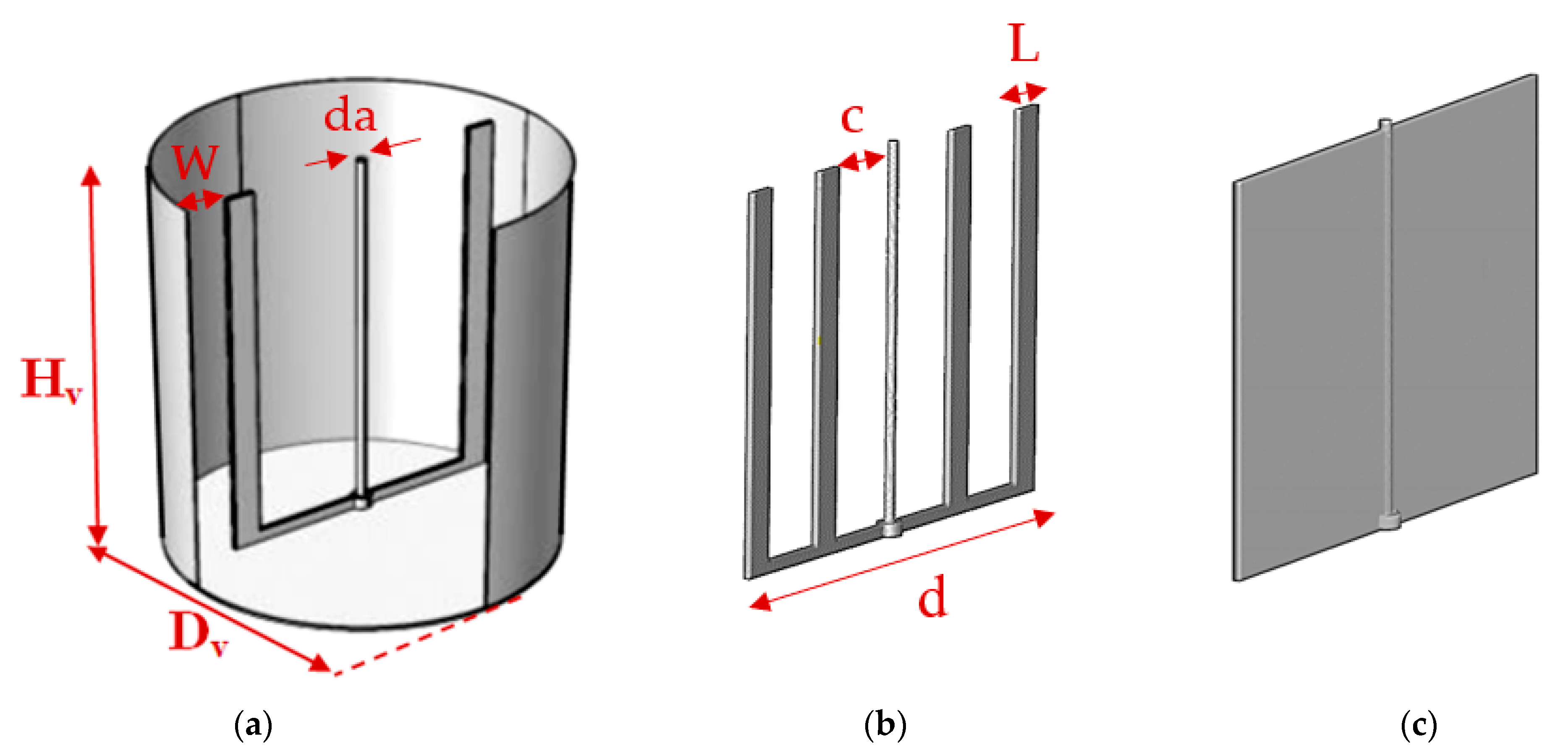
Figure 2.
Computation domain mesh (anchor impeller).

Figure 3.
Tangential velocity on the median plane obtained for the three sets of grids.
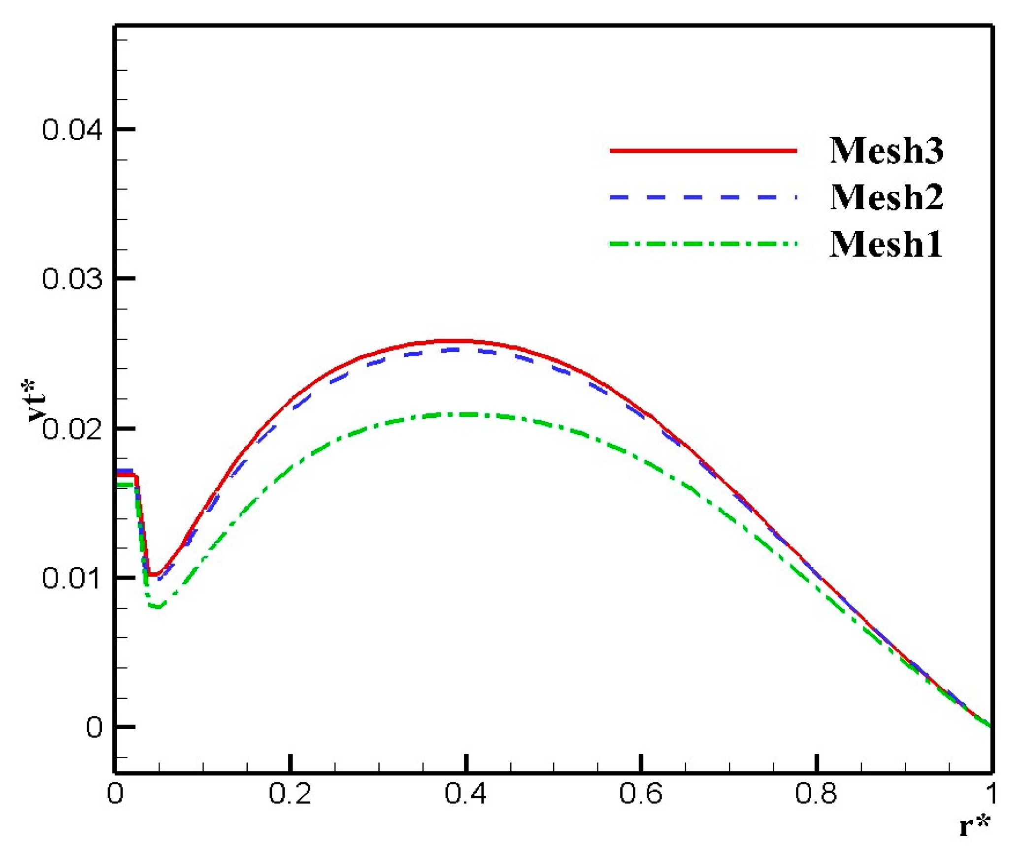
Figure 4.
Comparison of the tangential velocity on the blade plane of the CFD model and numerical results of refs. [33,34].
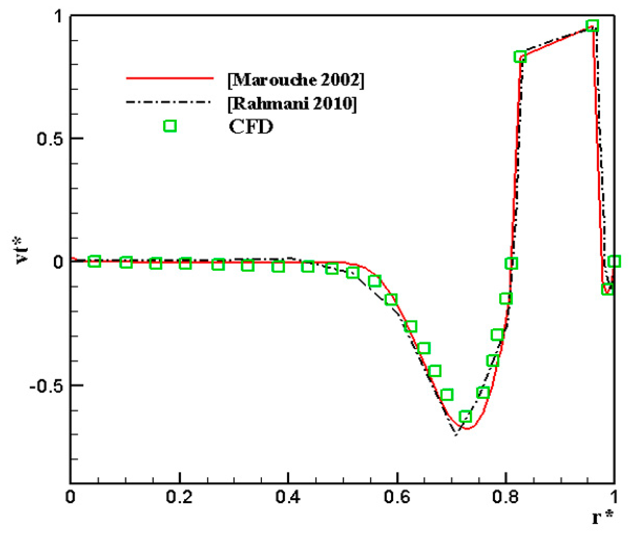
Figure 5.
Stream function comparison for different Reynolds numbers: (a) anchor impeller; (b) gate impeller; (c) two-bladed impeller.
Figure 5.
Stream function comparison for different Reynolds numbers: (a) anchor impeller; (b) gate impeller; (c) two-bladed impeller.
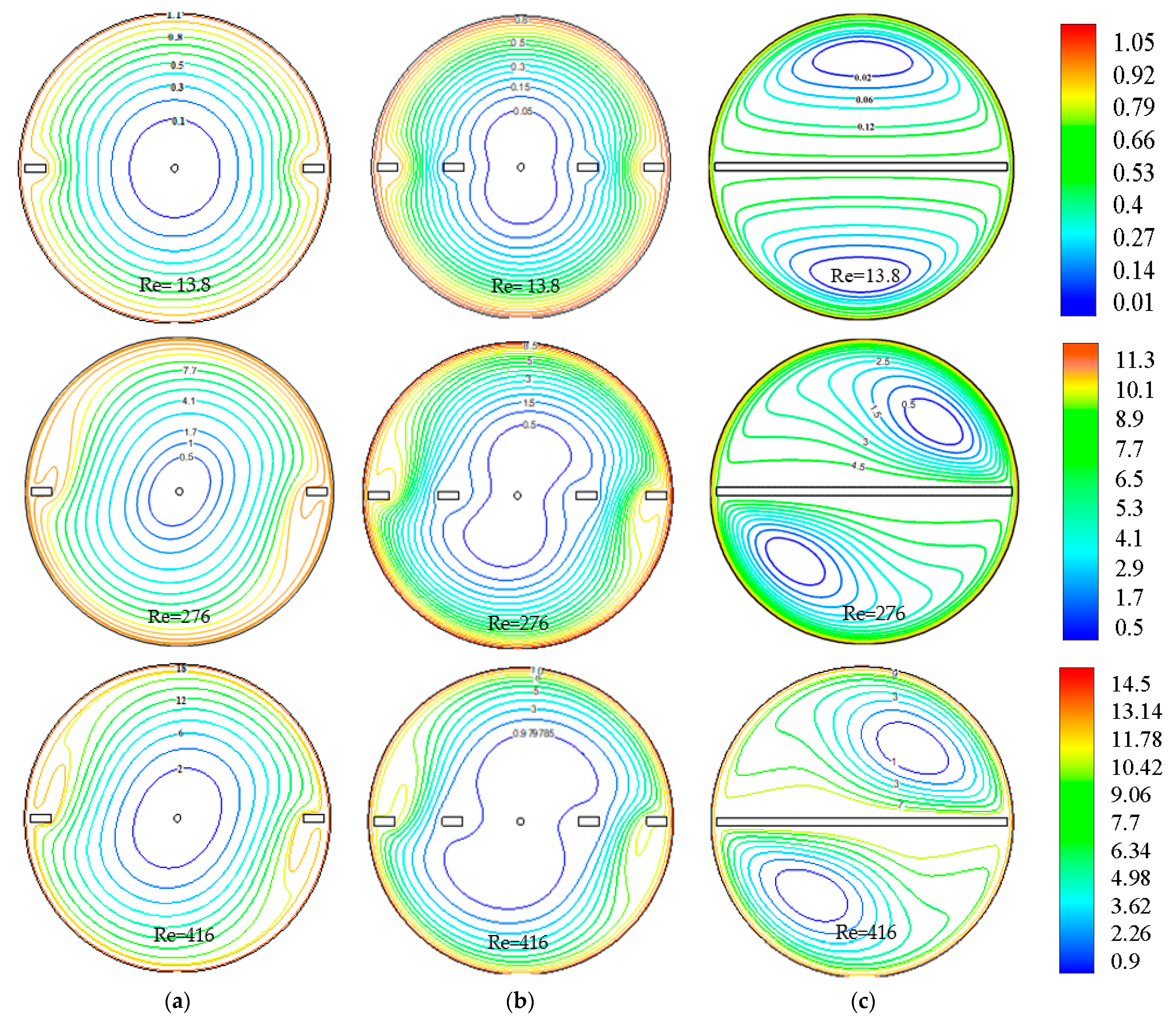
Figure 6.
Tangential velocity profiles on the impeller plane for the three impellers: (a) Re = 13.8; (b) Re = 416.
Figure 6.
Tangential velocity profiles on the impeller plane for the three impellers: (a) Re = 13.8; (b) Re = 416.

Figure 7.
Tangential velocity profiles on the median plane for the three impellers: (a) Re = 13.8; (b) Re = 416.
Figure 7.
Tangential velocity profiles on the median plane for the three impellers: (a) Re = 13.8; (b) Re = 416.
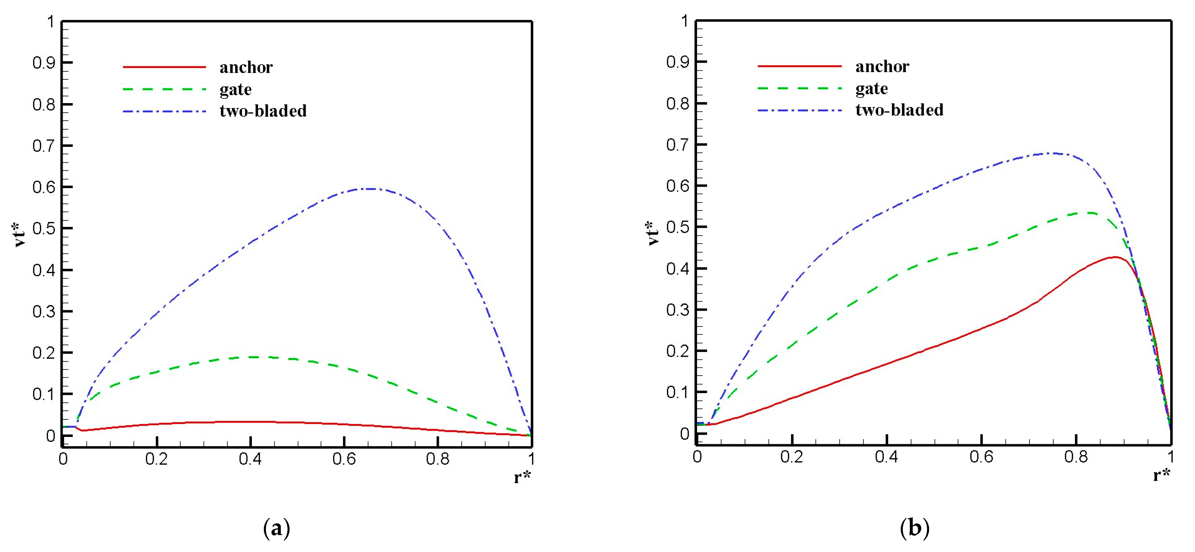
Figure 8.
Velocity contour distribution for different Bingham numbers: (a) anchor impeller; (b) gate impeller; and (c) two-bladed impeller.
Figure 8.
Velocity contour distribution for different Bingham numbers: (a) anchor impeller; (b) gate impeller; and (c) two-bladed impeller.

Figure 9.
Velocity vector field and velocity contour distribution for different yield stress : (a) anchor impeller; (b) gate impeller; and (c) two-bladed impeller.
Figure 9.
Velocity vector field and velocity contour distribution for different yield stress : (a) anchor impeller; (b) gate impeller; and (c) two-bladed impeller.
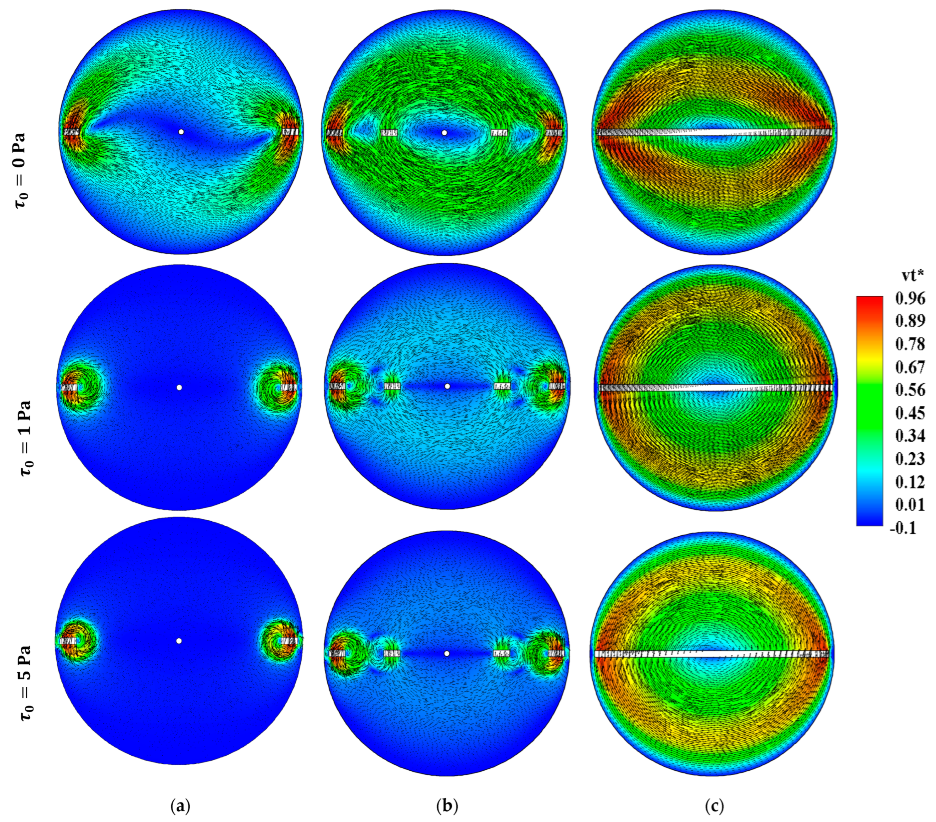
Figure 10.
Temperature field comparison for different Reynolds numbers: (a) anchor impeller; (b) gate impeller; and (c) two-bladed impeller.
Figure 10.
Temperature field comparison for different Reynolds numbers: (a) anchor impeller; (b) gate impeller; and (c) two-bladed impeller.

Figure 11.
Evolution of average Nusselt number as function of time for the three impellers.
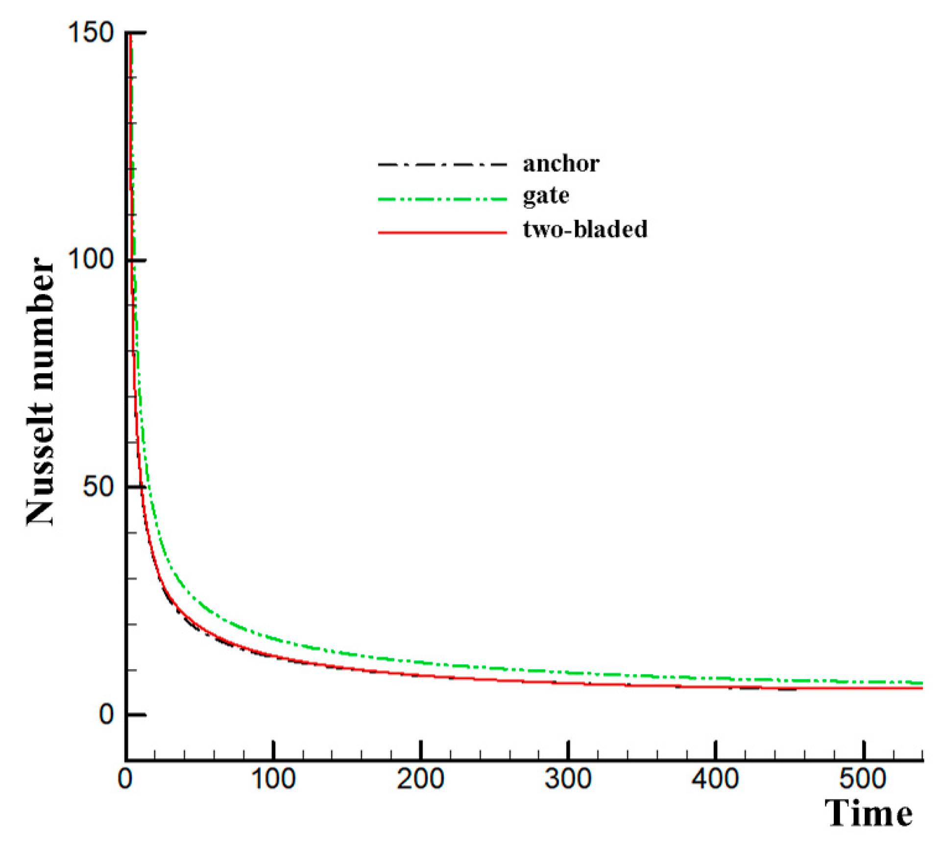
Figure 12.
Power consumption variation as a function of Reynolds number for the three impellers.

Figure 13.
Power consumption variation as a function of Bingham number for the three impellers.
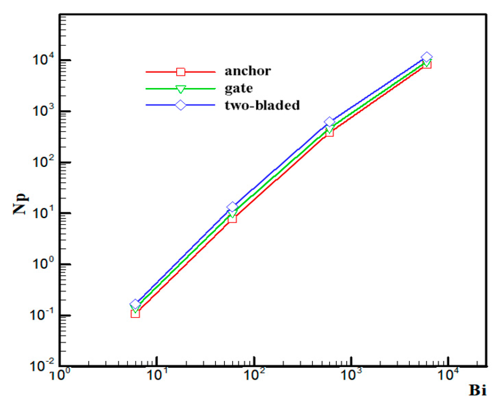
Figure 14.
Power consumption variation as a function of yield stress for the three impellers.


Table 1.
Recent studies on mixing non-Newtonian fluids with close clearance impellers.
| Impeller Type | Fluid Studied | Contribution | Refs. |
|---|---|---|---|
| Anchor-helical impellers | Shear-thinning fluid | Highlighted the pivotal role of impeller height in overall mixing system performance. | [7] |
| Anchor impeller + Scaba 6SRGT | Shear-thinning fluid | Combined an anchor impeller with a Scaba 6SRGT turbine, achieving notable improvements in cavern size, especially near the impeller axis. | [8] |
| Circular anchor impeller | Viscoplastic fluid | Conducted a numerical exploration of a circular-shape anchor impeller design for mixing yield stress fluids, presenting advantages such as improved flow field patterns and reduced energy consumption costs. | [9] |
| Anchor impeller | Viscoplastic fluid | Determined optimal values for stirrer clearance and width-to-vessel diameter ratios. Found that the four-bladed anchor impeller outperformed the two-bladed variant in terms of mixing efficiency. | [10] |
| Modified anchor impeller configuration | Shear-thinning fluid | Employed a modified impeller configuration and studied the impact of geometric design, anchor curvature, and shear zone on energy consumption. | [16,17] |
| Double helical ribbon, anchor, gate, Maxblend impellers | Shear-thinning fluid | Investigated the flow energy efficiency. Maxblend impeller demonstrated superior mixing quality and lower energy consumption in cylindrical tanks. | [18] |
| Anchor impellers with different blade shapes | Viscoplastic fluid | Compared different anchor blade shapes. The octagonal blade shape provided the broadest well-stirred region. | [19] |
| Anchor agitators | Viscoplastic fluid | Explored rheological parameters effects on flow and power consumption. | [20] |
| Anchor and paddle impellers | Mixing characteristic using tracer particles | Investigated geometric parameters’ impact on the anchor and plate impellers on fluid mixing characteristics, with a focus on achieving uniform fluid spreading. | [21] |
| Anchor impeller with different horizontal blades | Viscoplastic fluid | Investigated different geometric designs and inclination angles of anchor blades. Found that the anchor impeller with a 60° inclination exhibited the most efficient acceleration of flow. | [22] |
| Coaxial mixers: anchor with A200 impeller, ARI impeller and Rushton turbine | Shear-thinning fluid | Highlighted the significance of the interaction between the central impeller type and speed in determining coaxial power consumption. | [23] |
| Coaxial mixers: CBY or Pfaudler impeller combined with anchor or helical ribbon | Shear-thinning fluid | Showed that the Pfaudler helical ribbon configuration stood out as the optimal choice, yielding the shortest mixing time with same power consumption. | [24] |
| Scaba-anchor coaxial mixer | Shear-thinning fluid | Revealed that mixing efficiency was higher in the co-rotating mode compared to the counter-rotating mode. | [25,26] |
| Coaxial mixers: anchor with Cowles turbine, four-pitched blade turbine or three-blade propeller impellers | Viscoelastic fluid | Showed that the four-pitched blade turbine combined with an anchor impeller achieved the shortest mixing time with less power consumption. | [27] |
Table 2.
Dimensions of the simulated system.
| Dv | d | da/Dv | e/Dv | L/Dv | W/Dv | c/Dv |
|---|---|---|---|---|---|---|
| 300 mm | 288 mm | 0.023 | 0.027 | 0.067 | 0.02 | 0.167 |
Disclaimer/Publisher’s Note: The statements, opinions and data contained in all publications are solely those of the individual author(s) and contributor(s) and not of MDPI and/or the editor(s). MDPI and/or the editor(s) disclaim responsibility for any injury to people or property resulting from any ideas, methods, instructions or products referred to in the content. |
© 2023 by the author. Licensee MDPI, Basel, Switzerland. This article is an open access article distributed under the terms and conditions of the Creative Commons Attribution (CC BY) license (https://creativecommons.org/licenses/by/4.0/).
Share and Cite
MDPI and ACS Style
Benmoussa, A. Agitation of Viscoplastic Fluid in a Rotating Vessel Using Close Clearance Agitators. Eng 2023, 4, 2525-2541. https://doi.org/10.3390/eng4040144
AMA Style
Benmoussa A. Agitation of Viscoplastic Fluid in a Rotating Vessel Using Close Clearance Agitators. Eng. 2023; 4(4):2525-2541. https://doi.org/10.3390/eng4040144
Chicago/Turabian StyleBenmoussa, Amine. 2023. "Agitation of Viscoplastic Fluid in a Rotating Vessel Using Close Clearance Agitators" Eng 4, no. 4: 2525-2541. https://doi.org/10.3390/eng4040144