
Influence of a Shaft Shoulder on the Torsional Load-Bearing Behaviour of Trochoidal Profile Contours as Positive Shaft–Hub Connections
Department of Mechanical and Automotive Engineering, Institute for Machin Development, Westsächsische Hochschule Zwickau, D-08056 Zwickau, Germany
*
Author to whom correspondence should be addressed.
Eng 2024, 5(2), 834-850; https://doi.org/10.3390/eng5020045
Submission received: 29 March 2024
/
Revised: 26 April 2024
/
Accepted: 30 April 2024
/
Published: 11 May 2024
Abstract
:Shafts with a stepped shoulder are particularly well known in the field of drive technology. In combination with a form-fit shaft–hub connection, the shaft shoulder fixes the hub on the shaft as well as being responsible for the absorption of the axial forces. With profiled shafts, there is a notch overlay in the shaft shoulder, involving the shaft shoulder and profile. If the hub is also connected with the profiled shaft, the hub edge acts as an additional notch in the shaft shoulder area. The multiple resulting notches have not previously been part of research activities in the field of innovative trochoidal profile connections. Compared to conventional positive-locking connections, such as the keyway connection or the involute splined shaft profile, the favourable features of trochoidal profiles have only been based on connections with stepless shafts without a shoulder in previous studies. Accordingly, this article addresses numerical and experimental investigations of trochoidal profile connections with offset shafts for pure torsional loading. Focusing on a hybrid trochoid with four eccentricities and six drivers, a well-founded numerical and experimental investigation was carried out with numerous fatigue tests. In addition, the influence of a shaft shoulder was also demonstrated on simple epitrochoidal and hypotrochoidal profiles.
1. Introduction
The so-called M-profiles are innovative hybrid trochoids, which were developed at the Westschächsische Hochschule Zwickau, Germany [1] and have been investigated in several research projects (e.g., [2]). In comparison with commercially available connections such as splined shaft connections (standardised according to DIN 5480 [3]) and keyway connections (standardised according to DIN 6885 [4]), M-profile connections show a higher load-bearing capacity. Such connections have also found industrial interest and applications [2] in the recent years. In the field of simple hypotrochoids with only one eccentricity, which are standardised as so-called H-profiles according to DIN 3689 [5], great advantages have been observed regarding the dynamic load-bearing behaviour of these connections under rotational bending with static torsion [6].
In practical applications, shaft shoulders are provided due to the design of the shaft. These cause an additional notch, which influences the strength of the shaft or the connection. In [7], Neuber presents equations for determining the stress concentration factor for primarily round and singular shaft cross-sections for several classical cases. These equations were deduced on the basis of the mathematical formulation of the theory of elasticity using complex functions and conformal mappings, and are of very high scientific quality. In contrast, Peterson [8] presents practical diagrams and empirical equations for determining the stress concentration factor in stepped shafts for numerous practical cases. To determine the notch coefficient, Peterson made a very generalised suggestion that the notch coefficient and the stress concentration number should be set equally, which would only be roughly suitable for brittle materials. Neither of these two standard works deals with non-circular profiles such as P3G-profiles [9]. The effects of fretting corrosion in the joints of dynamically stressed shaft–hub connections and the determination of a corresponding notch efficiency were also not dealt with in the classic works mentioned above. This topic was first investigated by Reinholz [10], Göttlicher [11] and Großmann [12] on standardised P3G-profiles. In his work [13], Daryusi investigated the influences of tool run-out in shafts hobbed in accordance with DIN 5480 [3], which is not actually a shaft shoulder.
The shoulder effects can be superimposed with the effects of fretting corrosion in the connection, which can be varied depending on the distance between the hub edge and the shaft shoulder as well as the profile geometry [14].
In the present work, numerical and experimental investigations of trochoidal shaft–hub connections were carried out and the influences of the shaft shoulder on the stresses and on the fatigue limit were studied.
2. Profile Geometry
The geometric descriptions of different types of trochoids were presented in detail in [15], which is why they will not be discussed in detail here. Figure 1 shows the high geometric variability in hybrid trochoids when changing the profile parameters, namely the main eccentricity (top row) and number of corners n (bottom row). Increasing both of these profile parameters results in an increasing degree of positive locking when the profile is used as a form-fit shaft-and-hub connection.
The so-called M-profiles, as representatives of hybrid trochoids, can be described in general according to Equations (1) and (2) for the Cartesian x- and y-coordinates:
Here, r: nominal radius; … and … single eccentricities as functions of the main eccentricity ; … : functions of the parameter angle t and the number of corners n.
Due to any number of individual eccentricities to , which, in turn, represent functions of the main eccentricity and the number of corners n, hybrid trochoids have, as already mentioned, a high geometric adaptability compared to trochoids with only one profile eccentricity.
The M6-profile contour shown in Figure 2 represents a hybrid trochoid with four single eccentricities and n = 6 corners and is the focus of this article. The results for this profile type largely originate from an M6-profile with a higher main eccentricity from [14].
This M6-profile was optimised for an application in relation to a keyway connection [15]. The results of our numerical investigations on the influence of the shaft shoulder on the stress state in the connection under a static torsional load are presented below. The dynamic load-bearing behaviour is also discussed in a direct comparison of connections with a stepless shaft (without a shoulder) and a stepped shaft on the basis of component tests using Hück’s stair-step method [16].
3. Numerical Investigations of Static Torsional Load
In order to determine the influence of the shaft shoulder on the mechanical stress load, connections with stepless and stepped M6-profile shafts were simulated and the obtained results were compared. The term stepless shaft is used here to refer to a shaft without a shaft shoulder. The basis for this comparison was the M6-profile shown in Figure 2. For the simulation, a static torsional load was used.
3.1. Finite Element (FE) Model Structure
In order to reduce the computational effort, only one symmetry unit of the connection was modelled for the Finite element analysis, FEA (here, one-sixth of the complete connection). Figure 3 shows the basic model structure.
It is known from numerous numerical studies, e.g., [1,2], that the maximum stress occurs in the contact between the shaft and the hub in the area of the hub edge in the case of pure torsion load. With this in mind, the mesh density was increased in this area, as shown in Figure 3. The FE model was mainly meshed with fully integrated hexahedral elements. The core of the shaft and small areas on the outer diameter of the hub, which are not relevant for our evaluation, have pentahedron elements (“wedge” elements [17]). The shaft was clamped across all nodes on the end face (the blue face in Figure 3). However, the nodal displacements in the z-coordinate direction were left free due to the curvature of the profile cross section under torsional stress. For a stable calculation, all nodal displacements on the shaft axis in the three coordinate directions were blocked. The static torsional moment was introduced into the connection by means of a reference node, which was connected to all nodes on the outer diameter of the hub via rigid body elements (see Figure 3). Due to the thick-walled nature of the hub, there was no influence of the boundary condition on the outer diameter on the stress state in the joint. A coefficient of friction of µ = 0.12 was simulated in the contact. The fit between the shaft and the hub has an influence on the mechanical stress in the contact area, as shown by the authors of [2]. However, this influencing parameter is not part of this article, which is why an idealised zero clearance between the shaft and hub was simulated in the FEA. Consequently, a node-on-node modelling of the shaft and hub was applied in the contact area.
On the basis of the typical damage patterns observed on trochoidal profile joints, as shown, for example, on an M6-profile on the basis of dynamic component tests in [2], the following stress variables were selected for our numerical investigations:
- -
- Von Mises stress σv,mises;
- -
- Maximum principal stress σ1;
- -
- Contact normal stress σnn.
3.2. Load Condition in the Connection with Stepless Profile Shaft
In the first step, the M6-profile connection with a stepless shaft was simulated. This formed the reference for the following comparative tests. A static torsional moment of = 600 Nm and linear–elastic material behaviour was selected. As can be seen in Figure 4, based on the numerical distribution of the equivalent stress , there was a localised increase in stress in the joint between the shaft and the hub in the hub edge area. This was caused by the stiffness leap due to the hub, which overlayed the flank intervention between the shaft and hub at this point.
Figure 5 shows the curves of the relevant stress variables in the circumferential direction via a symmetry unit for the shaft. Due to the symmetrical stress distribution in pure torsion, this representation is sufficient. The arc length l of a symmetry unit and the curvilinear coordinate s were introduced for visualisation purposes. Our evaluation was conducted on the axial position of the hub edge.
The normal contact stress shows the range in which there is flank contact between the shaft and hub. Values of > 0 N/mm2 correspond to a contact. Outside this range, the connection opens up. Shortly before the flank engages, a maximum of the maximum principal stress is formed on the side of the flank subjected to tensile stress. Comparative stress is also shown. Only the shaft was analysed numerically, as it generally fails in combination with a sufficiently thick-walled hub, as observed in this study. The curves depicted in Figure 5 served as references for the following procedure.
3.3. Superimposed Influence of the Hub Edge and the Shaft Shoulder
On a real component, the modelled stepless profiled shaft transitions into the cylindrical part via a bonded run-out, as shown in Figure 6 (left). The shape of the run-out depends on the underlying manufacturing process for the trochoidal profile. In the case of a bonded run-out, however, no defined axial alignment of the hub on the profiled shaft is possible. In technical applications, the shaft shoulder therefore becomes established as a contact shoulder for a pushed-on hub, as can be seen for the M6-profile in Figure 6 on the right. In combination with a spacer sleeve, this enables defined axial positioning of the hub on the shaft. It also enables axial forces to be absorbed via the shaft shoulder. The profile-following rounding radius in the shaft shoulder here is = 1 mm. This results in a double notch from the M6-profile contour and shaft shoulder, which is part of the investigations below. A profile-following (see, e.g., DIN 509 [18]) undercut may also be conceivable at this point.
As the hub is shifted up to the shaft shoulder, this double notch is superimposed by the hub edge as a further notch. In order to determine the local stress superimposition in the shaft shoulder without the influence of the hub under a static torsional load, the distance a of the hub edge from the shaft shoulder was defined according to Figure 7. At a = 0 mm, the hub comes into contact with the shoulder.
Figure 8 shows the distribution of the critical-failure maximum principal stress with a torsional load and a distance of a = 4 mm between the hub edge and the shaft shoulder. It can be seen here that overstressing occurs in the area of the driver foot of the M6-profile in the fillet radius . Furthermore, there is a local stress maximum at the hub edge analogous to the result described in Section 3.2. The spatial separation of the two notch locations is clearly visible here.
In Figure 9 (left), the axial course of the maximum principal stress in the z-direction (see also Figure 7 on the right) is shown by the maximum of = 207.7 N/mm2 in the fillet radius of the shaft shoulder right into the joint. The two extreme points in the fillet radius and in the area of the hub edge at z = 4 mm are clearly recognisable. Here, the shaft shoulder represents a more critical notch point.
The right side of Figure 9 shows the dependence of the global stress maximum on the entire shaft as a function of the variable distance a. A convergence can be realised here. The most critical stress state occurs at a distance of a = 1 mm. The fillet radius of the shaft shoulder begins at this point. Due to the wire cutting of the profile contour, the hub examined in this experiment does not have a chamfer on the hub edge, which is why the hub could only be pushed onto the shaft up to a distance of a = 1 mm. This fact was taken into account in the FE simulation. The further the hub edge is pushed in the direction of the shaft shoulder, resulting in an increasing overlap of the notch points, the higher the mechanical stress load becomes.
Figure 10 also provides an insight into the curves of the relevant stress variables in the circumferential direction over a symmetry unit at the hub edge (left) and in the fillet radius of the shaft shoulder (right) at a distance of a = 4 mm. A significantly higher level of critical-failure maximum principal stress in the shaft shoulder is clearly recognisable. Compared to the smooth shaft in Figure 5 (right), there is even a slight reduction in the maximum principal stress at the hub edge. It is assumed that the shaft shoulder represents a kind of relief notch for the stress at the hub edge. However, this does not play a role in the failure of the M6-profiled shaft, as the more critical point is the shaft shoulder.
Based on the numerical results shown, the distance a between the hub edge and the shaft shoulder has a major influence on the maximum stress. However, as technical applications require the hub edge to be in contact with the shaft shoulder, this distance can be achieved by means of a sufficiently large chamfer on the hub edge. However, a chamfer represents a large geometric difference to the sharp-edged modelled hub edge, which must be investigated in further projects. In addition, the resulting stress increase in the fillet radius heavily depends on the profile eccentricity and the number of corners n. It can be assumed that a reduction in the eccentricity , for example, leads to a reduction in the load on the shaft shoulder and, therefore, more favourable behaviour. In the area of the connection, however, this reduction in eccentricity leads to a poorer degree of positive locking and, therefore, to a greater slip between the shaft and hub. This results in higher fretting corrosion under dynamic loads. However, the component tests of the M6-profile presented below show that the connection fails primarily due to a fretting-initiated crack. This would shift the point of failure from the shaft shoulder into the joint. This conflict of objectives must therefore be analysed in more detail in further investigations.
4. Experimental Investigations
In addition to our extensive FE simulations, dynamic component tests were carried out on the M6-profile shown in Figure 2. Besides the influencing parameter shaft shoulder, other parameters such as the shaft material, the fit between the shaft and hub, and the manufacturing technology used to produce the profiled shafts were analysed as part of these tests. A comparison of the connection variants was carried out on the basis of fatigue strengths and the resulting notch coefficients were determined in accordance with DIN 743-Part 1 [19]. The results are presented below and provide a good insight into the dynamic torsional load-bearing behaviour of the M6-profile as a function of the mentioned influencing parameters.
4.1. Test Bench and Test Parameters
The dynamic component tests were carried out on the electromechanical unbalanced-mass test rig shown in Figure 11. The dynamic torsional moment is generated by means of two rotating unbalanced masses offset by 180° on the left and right of the oscillating arm, which produce oppositely directed centrifugal forces. The load amplitude is a function of the speed and size of the unbalanced masses used, which are driven directly by an electric motor via a toothed belt. The required variable speeds and thus, as already mentioned, different load amplitudes are realised by means of a frequency converter. This test stand enables a maximum load amplitude of = ±2500 Nm. A defined centre load and thus tension can be generated by means of a pretensioning device installed on the oscillating arm, which statically twists the connection being tested. Furthermore, the connection being tested is connected to the main shaft via a metal bellows coupling. The torsional moment is finally transferred to the foundation via the hub, which is firmly bolted to the bearing pedestal. The torsional moment is measured via a torque-measuring shaft, which is located between the hub and the bearing pedestal, and the angle of rotation is measured using a rotation angle sensor at the end of the main shaft. The speed of the electric motor is determined using a speed sensor. The test stand is switched off after the specimen has been cracked when a previously defined limit angle of twist is reached, which is detected according to the angle of the rotation sensor.
A stress ratio of R = 0.2 was selected for the component tests, which corresponds to a pulsating torsional load. The obtained results are thus comparable to those of prior research, such as [6]. The test frequencies of the tests documented below corresponded to the set load horizon and were, therefore, variable. Furthermore, the shaft and hub were joined dry and tested without oil lubrication. However, technically relevant lubrication represents a further influencing parameter, which was left out in the present case.
4.2. Influence of a Shaft Shoulder on the Dynamic Transmission Capacity
The dynamic strength limit was determined on the basis of stair-step tests according to Hück [16]. The method will not be discussed in detail here, as it is well documented in [16]. The limit load cycle number was set to NG = 10 million load cycles. This value has become established in the field of form-fit connections, which fail due to frictional fatigue [6]. In the following procedure, the torsional notch effect number could be determined from the achieved endurance limit by recursively applying the calculation procedure in DIN 743-Part 1 [19].
Analogous to Section 3, the focus of these investigations is on the shaft shoulder. Connections with stepless M6-profiled shafts and stepped shafts were compared, as shown in Figure 12. A uniform joint length of = 46 mm and a sufficiently thick-walled hub with a hub outer diameter of = 70 mm were selected for the specimen geometry.
As can be seen in Figure 12, a fixed distance of a = 4 mm between the hub edge and the shaft shoulder was set for the stepped shaft. The background to this specification is the notch superposition already discussed in Section 3.3. Our numerical investigations at a sufficient distance “a” showed that the greatest chip mechanical stress is present in the fillet radius with a stepped shaft (see also Figure 10). However, as considerable fretting corrosion is to be expected in the dynamic process, particularly due to the tests carried out without oil lubrication, the exact failure location, i.e., whether the failure location is the shaft shoulder or joint area, should be determined in this way. If the hub had been pushed up to the shaft shoulder, it would not have been possible to clearly determine the cause of failure, i.e., whether failure occurred due to mechanical stresses or fretting corrosion. Table 1 shows the variants of the M6-profiled shaft–hub connections for the component tests, indicating the material and manufacturing processes used for the shafts and the fitting between the shaft and hub. They are labelled from A to D.
Figure 13 shows the comprehensive results of the stair-step tests. The achieved torsional dynamic strength limits are shown on the left and the calculated torsional notch coefficients βτ are shown on the right. All of the hubs in described in this figure were made of normalised C45R+N.
First of all, the major influence of the underlying manufacturing technology of the M6-profiled shafts is noticeable in the connections with stepless shafts. The hobbed shafts exhibit a 29% increase in their endurance limit compared to the shafts manufactured using the oscillating non-circular turning process. This is reflected in the lower notch coefficient βτ of the hobbed shafts, seen on the right in Figure 13. The hubs were all uniformly wire-cut.
The connection with the stepped and oscillating non-circular turned shaft resulted in an increase of 16% with = 85 N/mm2. This comparison confirms the numerical results discussed in Section 3.3, whereby the shaft shoulder represents a relief notch from a stress mechanics point of view. Compared to the FEA results, however, there is an even greater gap here. The tribological stress in the joint provides an explanation for this. Due to the shaft shoulder, the torsional rigidity of the M6-profiled shaft is greater than that of the stepless shaft. This increased torsional rigidity leads, in less relative movement, to the joint between the shaft and hub, which is why the tribological stress is reduced at this point and also has a strength-enhancing effect.
4.3. Interference between the Shaft and Hub
It is known from numerical investigations in [2,6] that a slight interference U between the shaft and hub can have a positive effect on the stress state of the joint. In order to confirm this finding purely experimentally, a connection variant with a slightly oversized U of ξ = U/da = 0.5‰ related to the circular tip diameter da (see Figure 2) was also investigated. Here, too, the FE simulation was confirmed with a slight increase in the endurance limit by 6%, as shown in Figure 13 on the left. In line with this result, the notch coefficient βτ decreases for the oversized variant.
Varying the shaft material from low-strength C45R+N to a hardened and tempered 42CrMoS4+QT material resulted in a 7% reduction in the impact strength, which was not expected (see also Figure 13). However, tests on simple hypotrochoids in [18] provided a comparable result. The high-strength material is significantly more sensitive to friction loading, which is why the increased strength cannot be utilised under dynamic stress during contact.
Figure 14 shows examples of the load-bearing patterns of three M6-profiled shafts subjected to endurance testing. The stepless shaft in Figure 14 on the left shows the typical crack initiation within the friction-corrosive damaged zone in the area of the hub edge. The crack initially develops in an axial direction. As the dynamic load progresses, a mechanical stress-induced crack growth typical of torsion sets in at an angle of 45° to the shaft axis, as can be seen in the example in the middle. The failure of the stepless shafts therefore occurs in the contact area around the hub edge. The stepped shaft in Figure 14 on the right shows a failure in the fillet radius of the shaft shoulder, which is thus a purely mechanical stress failure. The distance of a = 4 mm between the hub edge and the shoulder is clearly visible on the basis of the friction-corrosive damaged zone.
The failure modes thus confirm the numerical results discussed in Section 3.2 and Section 3.3 very well. With a stepped shaft, the fillet radius is subjected to significantly higher stresses than the joint area, provided that a sufficient distance a is present.
5. Epitrochoidal and Hypotrochoidal Connections with the Stepped Shaft
In addition to the M6-profile, which is a representative of a hybrid trochoid, simple epitrochoidal and hypotrochoidal connections were also investigated. The term “simple” in this context means that only one profile eccentricity is present. The following section presents the purely experimental results for these profiles. The results shown were generated as an extension of the investigations of the project in [2].
5.1. Geometry of Specimen
The hypotrochoid with n = 3 corners shown in Figure 15 on the left was taken from the standard DIN 3689-Part 1 [5]. The generation of this profile geometry is not discussed in detail here, as it is well documented in the aforementioned standard [5]. The mechanical properties of such profiles are discussed in detail for torsional loading in [20]. A uniform circular tip diameter of = 40 mm was selected to ensure comparability between the two simple trochoids. The simple epitrochoid in Figure 15 on the right also has n = 3 corners and was fitted into the same installation space. Its special feature is its flat profile flanks, which have an infinitely large radius of curvature in the driver base. A detailed description of this profile type, including the parameter equations for the Cartesian x- and y-coordinates, can be found in [21].
When comparing the two profile cross sections, the larger root diameter and, thus, the lower corner height of the E3-profile is particularly evident. In combination with the more strongly shaped corners, this results in a larger cross-sectional area A. However, the high geometric variability in the trochoids with a constant installation space becomes apparent. Table 2 summarizes an overview of the selected profile parameters for both profile types. The results of the endurance tests are presented in the following section. The designation of the profiles is in accordance with the standard E3- (epitrochoid) or H3-daxdi.
5.2. Dynamic Strength under Swelling Torsion
The dynamic tests were carried out in analogy to the M6-profile tests using the stair-step case method for the E3- and H3-profile connections, each with a stepless profiled shaft. The test parameters here correspond to those described in Section 4.1 and Section 4.2. Hubs made of normalised C45R+N steel were paired with shafts made of high-strength 42CrMoS4+QT steel. Furthermore, these profile variants were provided with a slight interference fit due to the geometrically lower degree of form fitting. The oversized U in relation to the circular tip diameter was ξ = U/ = 0.25 ‰. These were thick-walled hubs with a joint length of = 40 mm.
Figure 16 shows the achieved fatigue strength and notch coefficient βτ for each profile type for the load case of pulsating torsion.
Compared to the E3-profile, the H3-profile has an about 3.5% higher fatigue strength of = 90 N/mm2 and, thus, a slightly lower notch effect compared to the E3-profile, as can be seen on the right in Figure 16 in the comparison of the notch coefficients βτ. However, as mentioned, these results relate to the profile being connected with a stepless shaft.
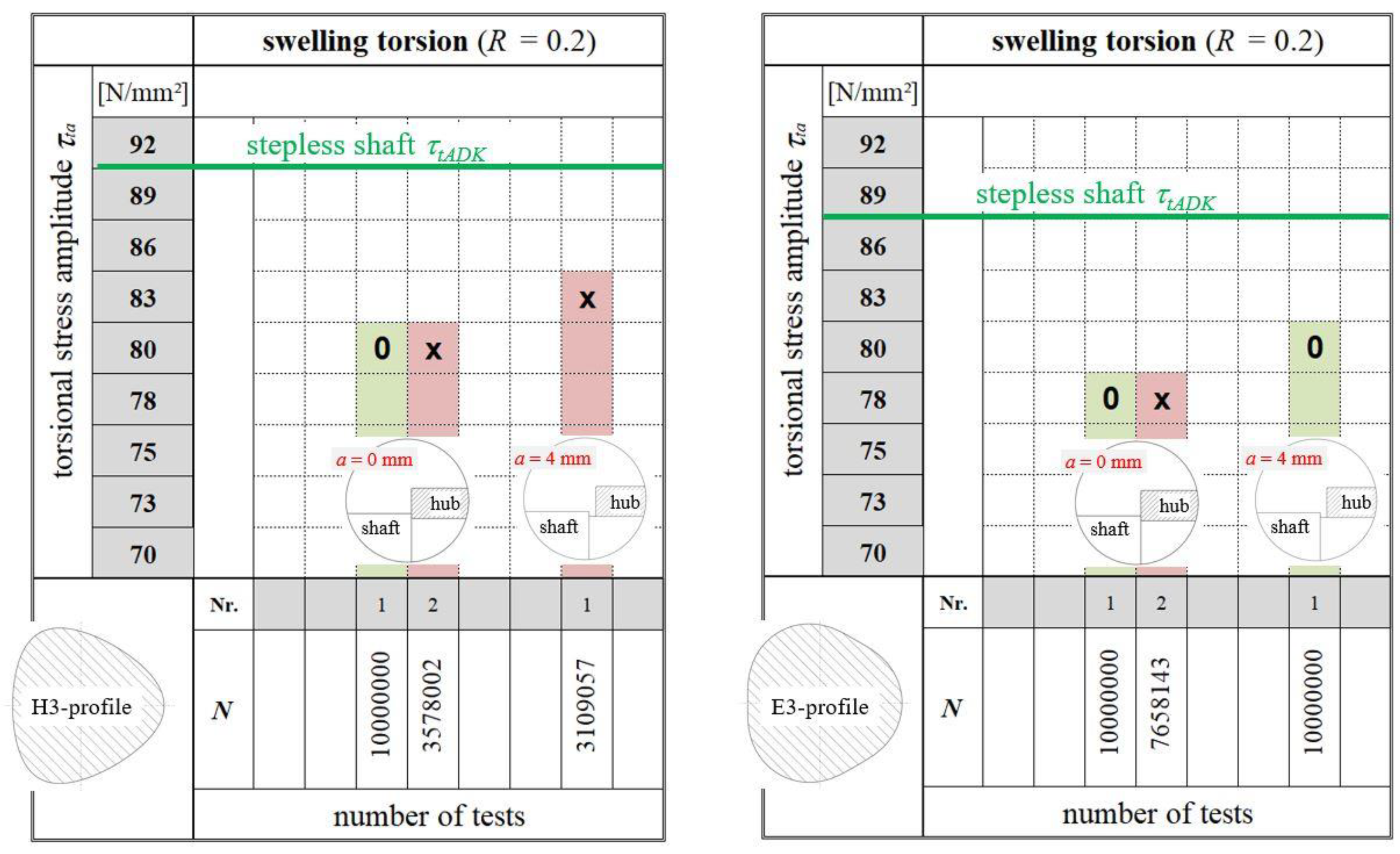
For the connections with a stepped shaft, however, only three connections were available in the project, which is why it was not possible to run a sequence of steps here and, thus, validly determine the fatigue strength . Based on Figure 17, the procedure for determining the influence of a shaft shoulder on these profile variants can be explained using three stitch tests.
In Figure 17, the achieved fatigue strength of the stair-step case test with the stepless shaft (Figure 16) for the H3-profile on the left and E3-profile on the right is marked with a green reference line. In addition, three stitch tests of the stepped shafts were conducted. In each case, two tests were carried out with the hub pushed up to the shaft shoulder, corresponding to a distance of a = 0 mm, and one test was performed with a distance of the hub edge to the shoulder of a = 4 mm (analogous to the M6-profile).
For the H3-profile, the load horizon with a torsional stress amplitude of = 80 N/mm2 resulted in one survivor (0), which reached the number of load cycles N = 10 million, and one fracture (x). This means that this load horizon is no longer in the fatigue strength range, which results in a significant reduction in the fatigue strength of = 90 N/mm2 of the stepless shaft. The fracture of the test with a distance a = 4 mm at N = 3.1 million load cycles does not initially suggest any strength-increasing influence of the distance a either. However, the number of samples studied is not sufficient for a reliable statement in this context.
The E3-profile on the right in Figure 17 shows a similar behaviour when the hub edge is in contact with the shaft shoulder. However, the test for the distance a = 4 mm resulted in a survivor, which indicates an increase in strength.
The experimental results from Figure 17 show a significant reduction in strength for both profile types when the hub edge is in contact with the shaft shoulder and thus confirm the numerically determined exponential increase in the maximum principal stress with the decreasing distance a in Figure 9 (right). The resulting multiple notches represent the most critical condition. However, the two stitch tests do not replace the complete stair-step case test with a valid fatigue strength , which should be determined in further research activities. However, they do indicate a general trend behaviour in this context. A comparison of the number of load cycles N achieved in the test with the stepped shafts generally shows improved notch behaviour with the E3-profile. On average, the number of load cycles N of the three tests is greater here compared to the H3-profile.
6. Conclusions and Outlook
This article addresses the influence of a shaft shoulder on the fatigue strength of trochoidal shaft-and-hub connections. The results discussed in previous publications on trochoidal profile connections with stepless shafts were evaluated primarily as an idealised reference. The numerical and experimental results discussed here show a large dependence of the static and dynamic torsional transmission capacity on the hub’s positioning on the stepped shaft. The further the hub is pushed in the direction of the shaft shoulder, the more notch overlapping occurs and, thus, the more the stress increases, which leads to a significant reduction in the fatigue strength under a swelling torsional load. It was found that there is a characteristic distance between the hub contact areaand the shaft shoulder, which results in an inversion, i.e., an increase in the dynamic transmission capacity. However, this characteristic distance is highly dependent on the trochoidal profile geometry, as shown by the results obtained with the M6-profile compared to those achieved with the simple epitrochoidal and hypotrochoidal profiles. It was also proven that the diameter ratio of the shaft shoulder is of great importance. This issue must be investigated more closely in further research efforts in the field of trochoidal connections.
In addition to the shaft shoulder, the shaft material was also varied for the M6-profile. Contrary to expectations, this resulted in a higher notch coefficient βτ for the higher-strength shaft material. As a result, it was found that due to the frictional corrosive damage in dynamic operation, the potential of the higher-strength material cannot be utilised due to its greater sensitivity to frictional corrosion.
Furthermore, a considerable increase in dynamic transmission capability was shown when using a slight interference between the shaft and hub and when using a hobbing process to manufacture the profiled shafts.
Compared to the hypotrochoidal profile, we found that the E3-profile has a slightly higher torsional notch coefficient βτ and, therefore, exhibits a slightly worse dynamic torsional load-bearing behaviour. In terms of the effects that a shaft shoulder induces on the overall strength, however, the H3-profile has a slight disadvantage due to its geometry.
Author Contributions
Conceptualization, M.Z. and H.S. methodology, M.Z.; software, M.Z. and H.S.; validation, M.Z., H.S. and M.S.; formal analysis, M.Z.; investigation, H.S.; resources, M.Z.; data curation, M.Z.; writing—original draft preparation, M.Z.; writing—review and editing, M.Z.; visualization, M.Z. and M.S.; supervision, M.Z.; project administration, M.Z. funding acquisition, M.Z. All authors have read and agreed to the published version of the manuscript.
Funding
This research was funded by German Research Foundation (Deutsche Forschungsgemeinschaft DFG), grant number: DFG ZI 1161/3. The authors extend their thanks to the DFG for funding this research project as well as SEW-Eurodrive GmbH & Co KG DTC Ost for their good co-operation.
Institutional Review Board Statement
Not applicable.
Informed Consent Statement
Not applicable.
Data Availability Statement
The original contributions presented in the study are included in the article, further inquiries can be directed to the corresponding author.
Acknowledgments
Professor Franz Gustav Kollmann is a German pioneer in the field of non-circular profile shaft-hub connections. He turns 90 in August, and the Authors would like to dedicate this article to him to mark the occasion. The authors would like to thank the Research and Transfer Centre Zwickau (FTZ) for supporting the testing of H- and E-profiles
Conflicts of Interest
The authors declare no conflict of interest.
Abbreviations
| Distance of the hub edge to the shaft shoulder; | |
| A | Surface area; |
| Tip diameter; | |
| Outer diameter of the hub; | |
| Root diameter; | |
| Eccentricity; | |
| Main eccentricity; | |
| Single eccentricity; | |
| FE | Finite element |
| FEA | Finite element analysis |
| l | Arc length; |
| Joining length; | |
| Torsional moment; | |
| n | Number of corners; |
| N | Number of load cycles; |
| Limit number of load cycles; | |
| Diameter ratio; | |
| Nominal radius; | |
| Fillet radius; | |
| R | Stress ratio (min/max); |
| s | Running coordinate; |
| t | Parameter angle; |
| Displacement in the spatial direction; | |
| U | Interference fit; |
| x | Cartesian coordinate; |
| y | Cartesian coordinate; |
| Notch coefficient; | |
| µ | Coefficient of friction; |
| Contact normal stress; | |
| Von Mises stress; | |
| Maximum principal stress; | |
| Torsional stress amplitude; | |
| Fatigue strength. |
References
- Ziaei, M. Optimale Welle-Nabe-Verbindung mit Mehrfachzyklischen Profilen, 5; VDI-Fachtagung “Welle-Nabe-Verbindungen”: Nürtingen, Germany, 2012. [Google Scholar]
- Ziaei, M.; Selzer, M. Entwicklung Kontinuierlicher Unrunder Innen- und Außenkonturen für Formschlüssige Welle-Nabe-Verbindungen und Ermittlung Analytischer Lösungsansätze; Forschungsvorhaben DFG-ZI1161-1/2, Abschlussbericht; Westsächsische Hochschule Zwickau: Zwickau, Germany, 2015. [Google Scholar]
- DIN 5480:2006-03. Involute Splines Based on Reference Diameters—Part 1: Generalities. Beuth-Verlag: Berlin, Germany, 2006.
- DIN 6885-1:1968-08. Drive Type Fastenings without Taper Action; Parallel Keys, Keyways, Deep Pattern. Beuth-Verlag: Berlin, Germany, 1968.
- DIN 3689-1:2021-11. Shaft to Collar Connection—Hypotrochoidal H-Profiles—Part 1: Geometry and Dimensions. Beuth-Verlag: Berlin, Germany, 2021.
- Vetter, S.; Leidich, E.; Ziaei, M.; Herrmann, M.; Hasse, A. Durability of hypotrochoidal shaft-hub connections under rotating bending with static torsion. Procedia Struct. Integr. 2019, 17, 90–97. [Google Scholar] [CrossRef]
- Neuber, H. Kerbspannungslehre: Theorie der Spannungskonzentration Genaue Berechnung der Festigkeit; Springer: Berlin/Heidelberg, Germany, 2013. [Google Scholar]
- Peterson, R.E. Stress Concentration Factors, 2nd ed.; Wiley-Interscience: New York, NY, USA, 1997. [Google Scholar]
- DIN 32711-1:2009-03. Shaft to Collar Connection—Polygon Profil P3G—Part 1: Generalities and Geometry. Beuth-Verlag: Berlin, Germany, 2009.
- Reinholz, R. Tragfähigkeit von P3G-Welle-Nabe-Verbindungen bei Dauerschwingbeanspruchung. Ph.D. Thesis, Technische Universität, Berlin, Germany, 1994. [Google Scholar]
- Göttlicher, C. Entwicklung einer Verbesserten Festigkeitsberechnung für P3G-Polygon-Welle-Nabe-Verbindungen bei Torsion und Kombinierter Biege und Torsionsbeanspruchung. Ph.D. Thesis, Technische Hochschule Darmstadt, Darmstadt, Germany, 1994. [Google Scholar]
- Großmann, C. Fretting Fatigue of Shape-Optimised Polygon-Shaft-Hub Connections. Ph.D. Thesis, Technische Universität, Berlin, Germany, 2007. [Google Scholar]
- Daryusi, A. Beitrag zur Ermittlung der Kerbwirkung an Zahnwellen mit freiem und gebundenem Auslauf. Ph.D. Thesis, Technische Universität, Dresden, Germany, 2009. [Google Scholar]
- Sommer, S.; Ziaei, M.; Kunert, J. Einflüsse des Wellenabsatzes auf das Tragverhalten der Welle-Nabe-Verbindung mit M04-Profil unter reiner Torsion. In VDI-Fachtagung “Welle-Nabe-Verbindungen” Dimensionierung—Fertigung—Anwendung und Trends; VDI Verlag: Düsseldorf, Germany, 2022; ISBN 978-3-18-092408-3. [Google Scholar]
- Ziaei, M. Bending Stresses and Deformations in Prismatic Profiled Shafts With Noncircular Contours Based on Higher Hybrid Trochoids. Appl. Mech. 2022, 3, 1063–1079. [Google Scholar] [CrossRef]
- Hück, M. Ein verbessertes Verfahren für die Auswertung von Treppenstufenversuchen. Mater. Werkst. 1983, 14, 406–417. [Google Scholar] [CrossRef]
- Marc 2022 Manual; MSC Software Corporation: Newport Beach, CA, USA, 2022; Volume B, (Element Library).
- DIN 509:2022-12. Technical Product Documentation—Relief Grooves—Types Dimensions and Tolerances. Beuth-Verlag: Berlin, Germany, 2022.
- DIN 743-1:2012-12. Calculation of Load Capacity of Shafts and Axles—Part 1: General. Beuth-Verlag: Berlin, Germany, 2012.
- Ziaei, M. Torsionsspannungen in prismatischen, unrunden Profilwellen mit trochoidischen Konturen. Forsch. Im Ingenieurwesen 2021, 85, 1–11. [Google Scholar] [CrossRef]
- Ziaei, M. Gegenüberstellung von K- und H-Profil-Welle-Nabe-Verbindungen, Übertragungsverhalten der epi- und hypotrochoidischen Profile für die Lastfälle Torsion und Biegung, VDI-Fachtagung “Welle-Nabe-Verbindungen” Dimensionierung—Fertigung—Anwendung und Trends; VDI Verlag: Düsseldorf, Germany, 2022; ISBN 978-3-18-092408-3. [Google Scholar]
Figure 1.
Geometric variability of a hybrid trochoid. The form-fit degree is increased by varying the main eccentricity (top row) and the number of corners n (bottom row).
Figure 1.
Geometric variability of a hybrid trochoid. The form-fit degree is increased by varying the main eccentricity (top row) and the number of corners n (bottom row).
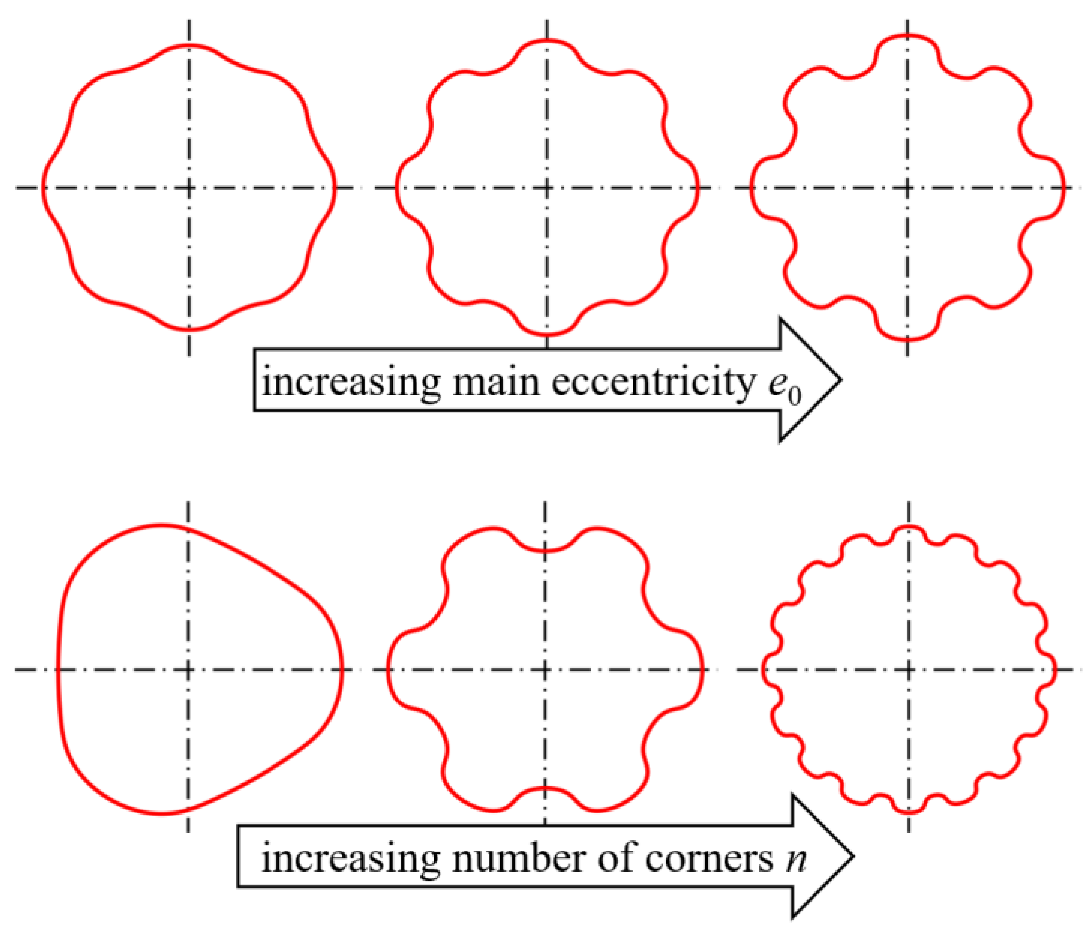
Figure 2.
Geometry of the M6-profile used for our numerical and experimental investigations [14].
Figure 2.
Geometry of the M6-profile used for our numerical and experimental investigations [14].
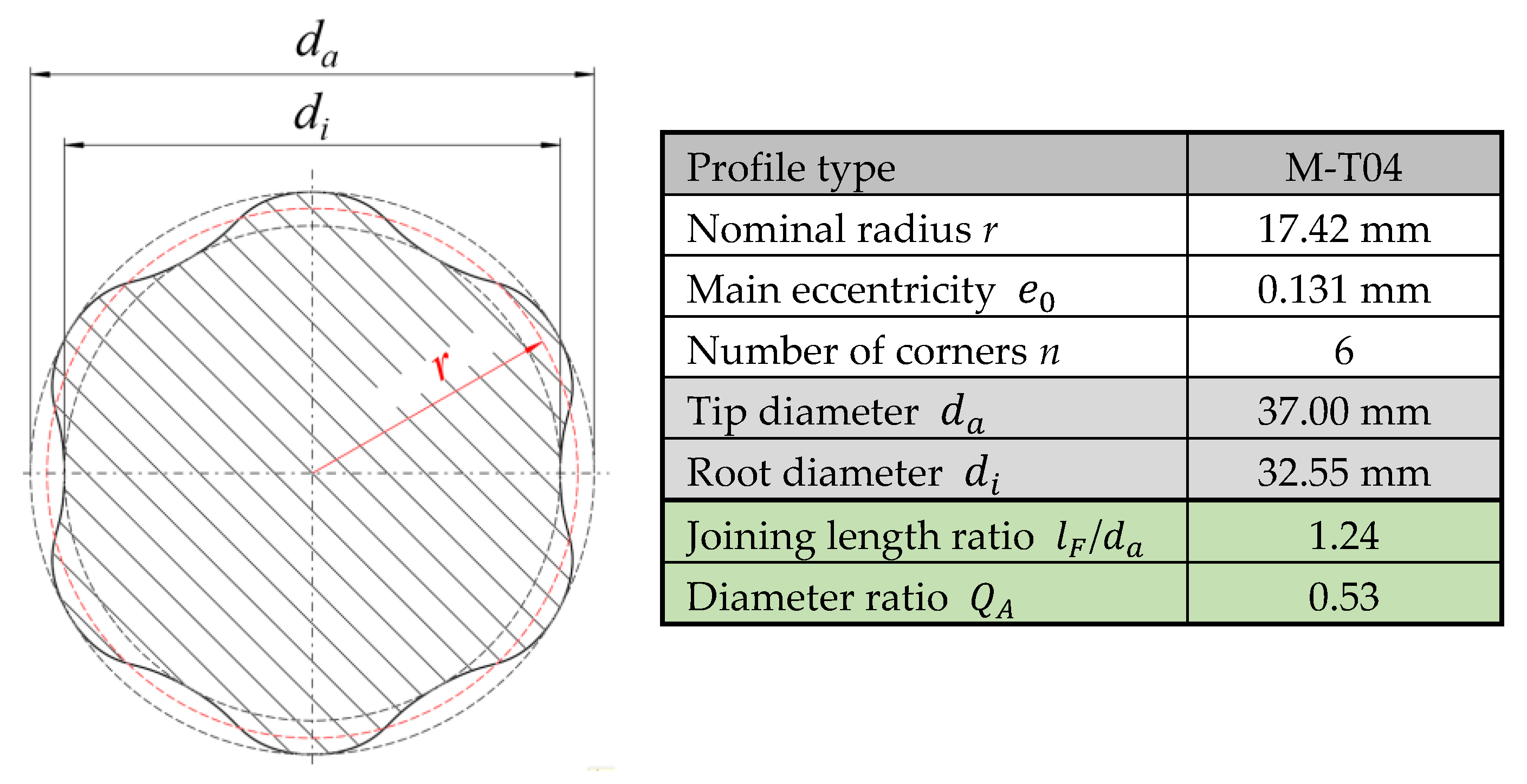
Figure 3.
Illustration of the FE model structure with the boundary conditions, simplified for a sector for the load case of pure torsion.
Figure 3.
Illustration of the FE model structure with the boundary conditions, simplified for a sector for the load case of pure torsion.
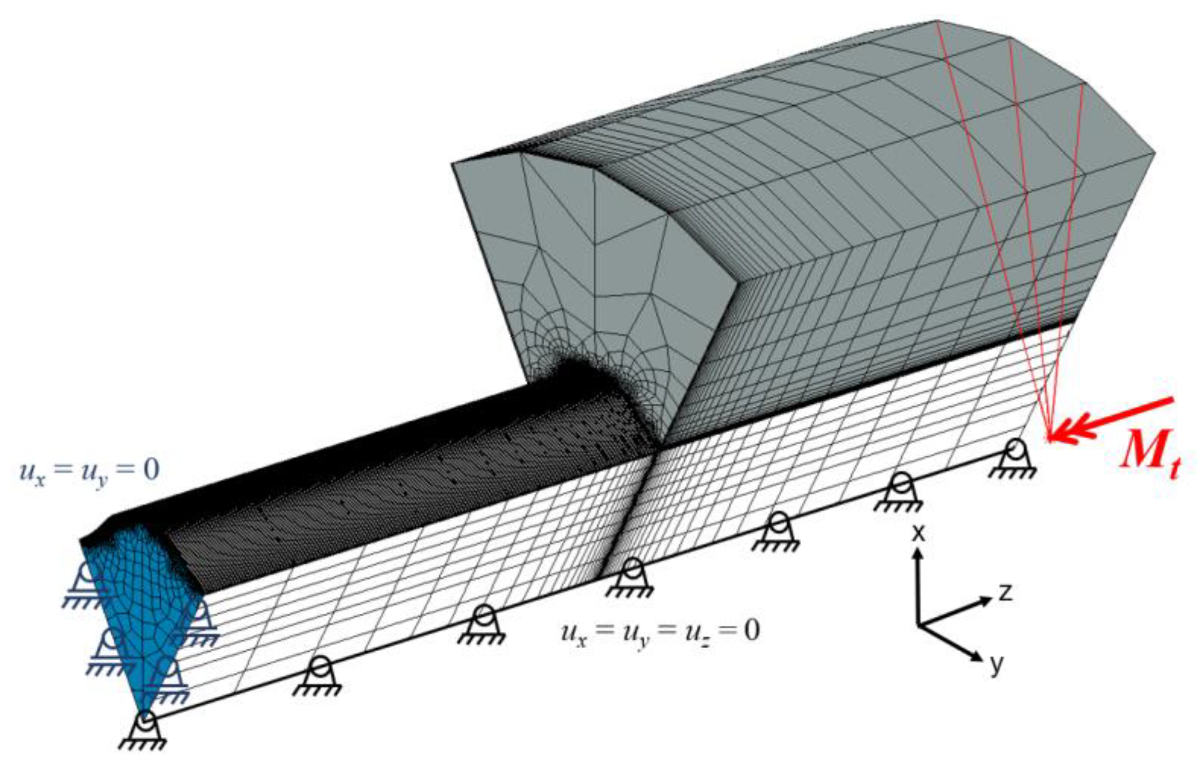
Figure 4.
Local stress increase in the joint between the shaft and hub in the area of the hub edge using the example of the equivalent stress according to Mises , Mt = 600 Nm.
Figure 4.
Local stress increase in the joint between the shaft and hub in the area of the hub edge using the example of the equivalent stress according to Mises , Mt = 600 Nm.
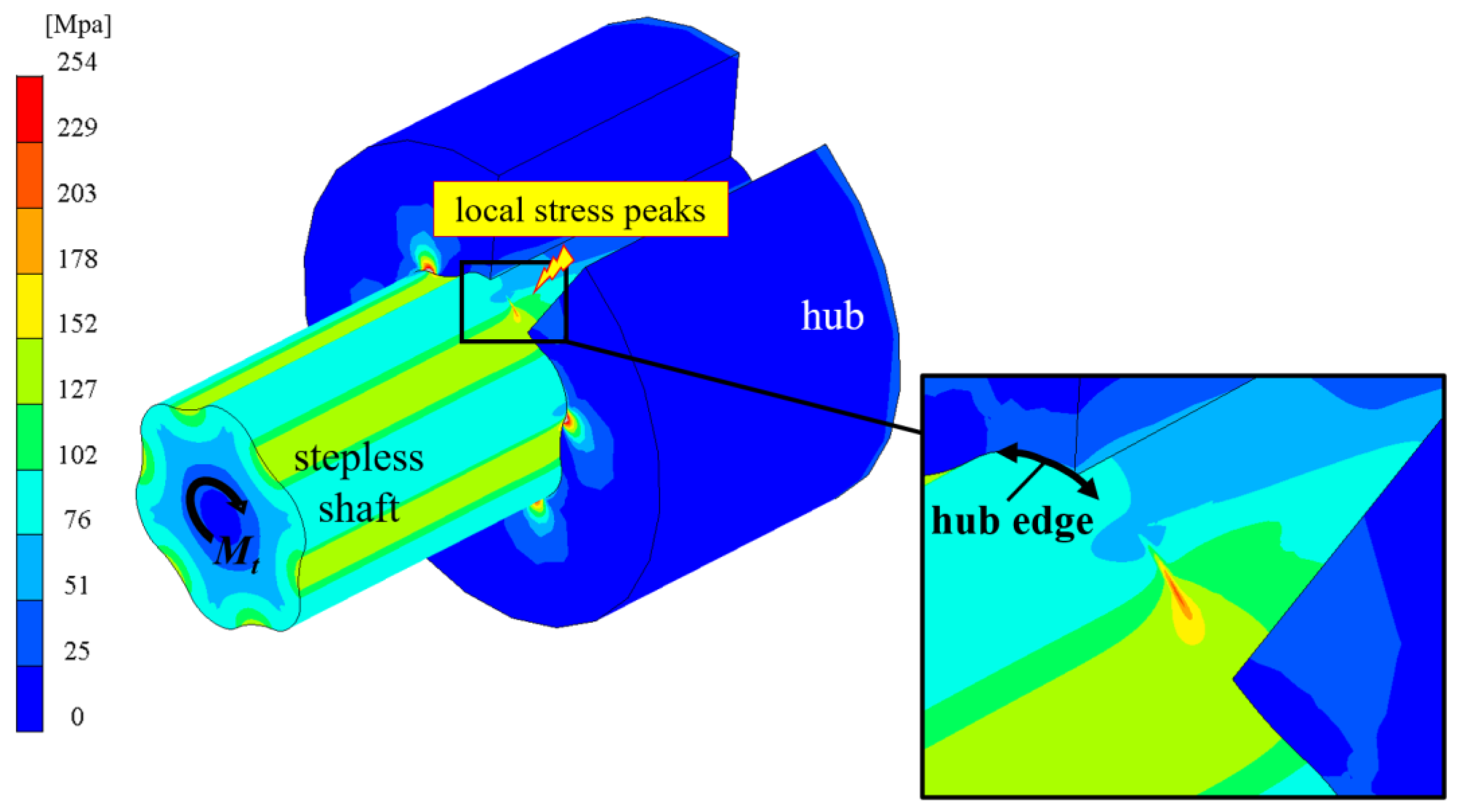
Figure 5.
Curve of the evaluation path between two driver heads of the shaft (left) and representation of the normal contact stress , the maximum principal stress , and the equivalent stress according to Mises (right), for = 600 Nm, with linear–elastic material behaviour and idealised zero clearance.

Figure 6.
Stepless shaft with bonded outlet without a shoulder (left) and profile-following fillet radius of = 1 mm in the shaft shoulder (right).
Figure 6.
Stepless shaft with bonded outlet without a shoulder (left) and profile-following fillet radius of = 1 mm in the shaft shoulder (right).
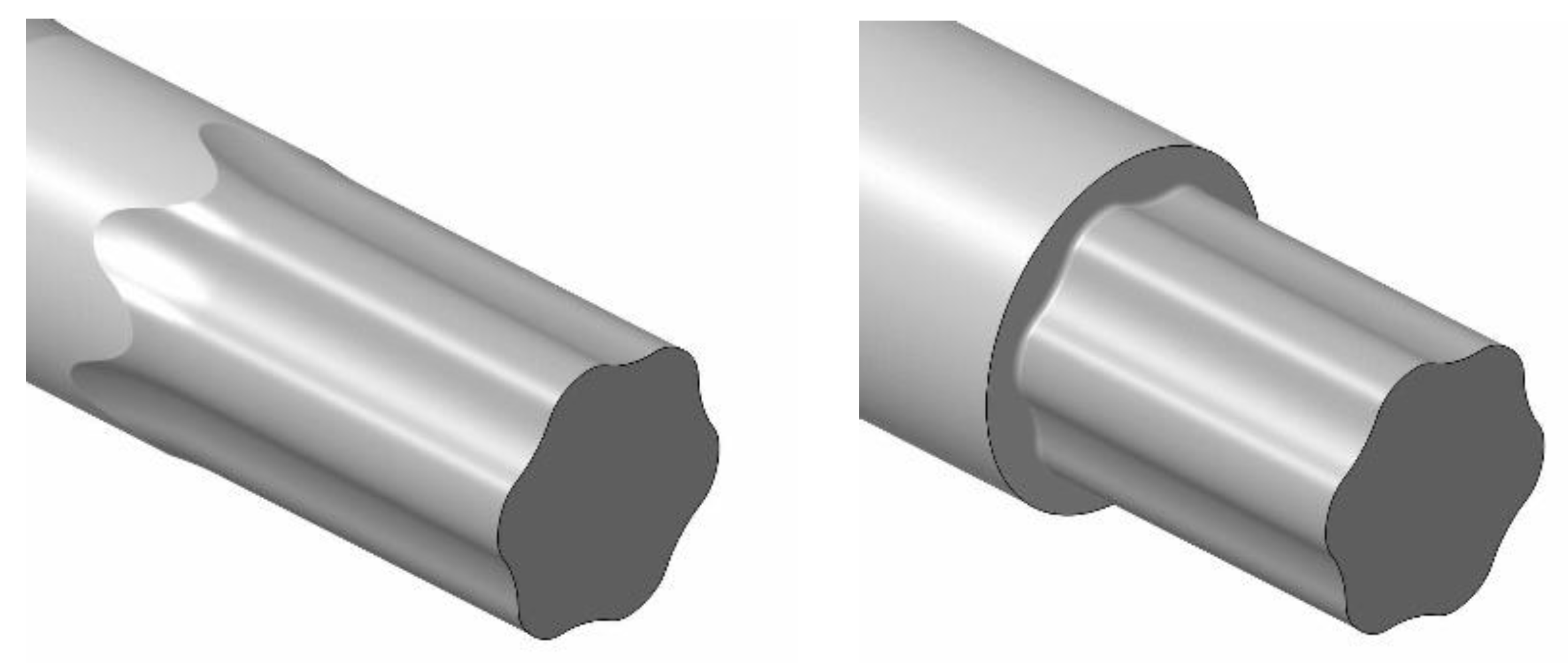
Figure 7.
Hub with a stepless M6-profile shaft indicating the distance a of the hub edge from the shaft shoulder and the fillet radius .
Figure 7.
Hub with a stepless M6-profile shaft indicating the distance a of the hub edge from the shaft shoulder and the fillet radius .
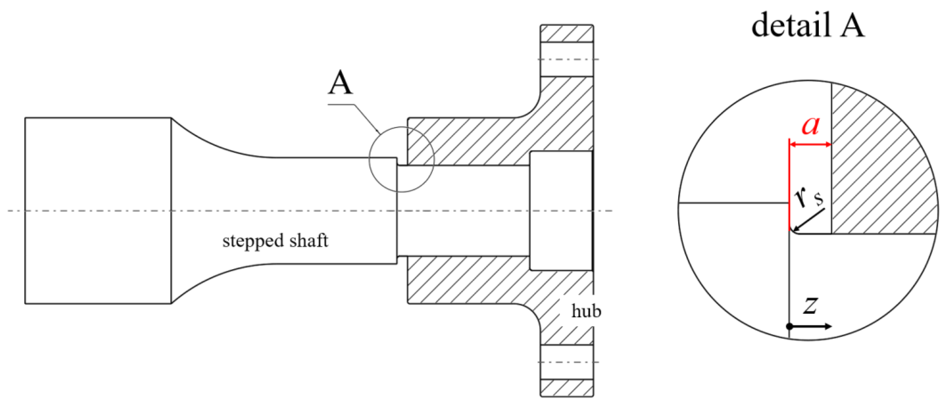
Figure 8.
Distribution of the maximum principal stress for a stepped M6-profiled shaft with a significant increase in stress in the fillet radius of the shaft shoulder and in the area of the hub edge; distance a = 4 mm.
Figure 8.
Distribution of the maximum principal stress for a stepped M6-profiled shaft with a significant increase in stress in the fillet radius of the shaft shoulder and in the area of the hub edge; distance a = 4 mm.
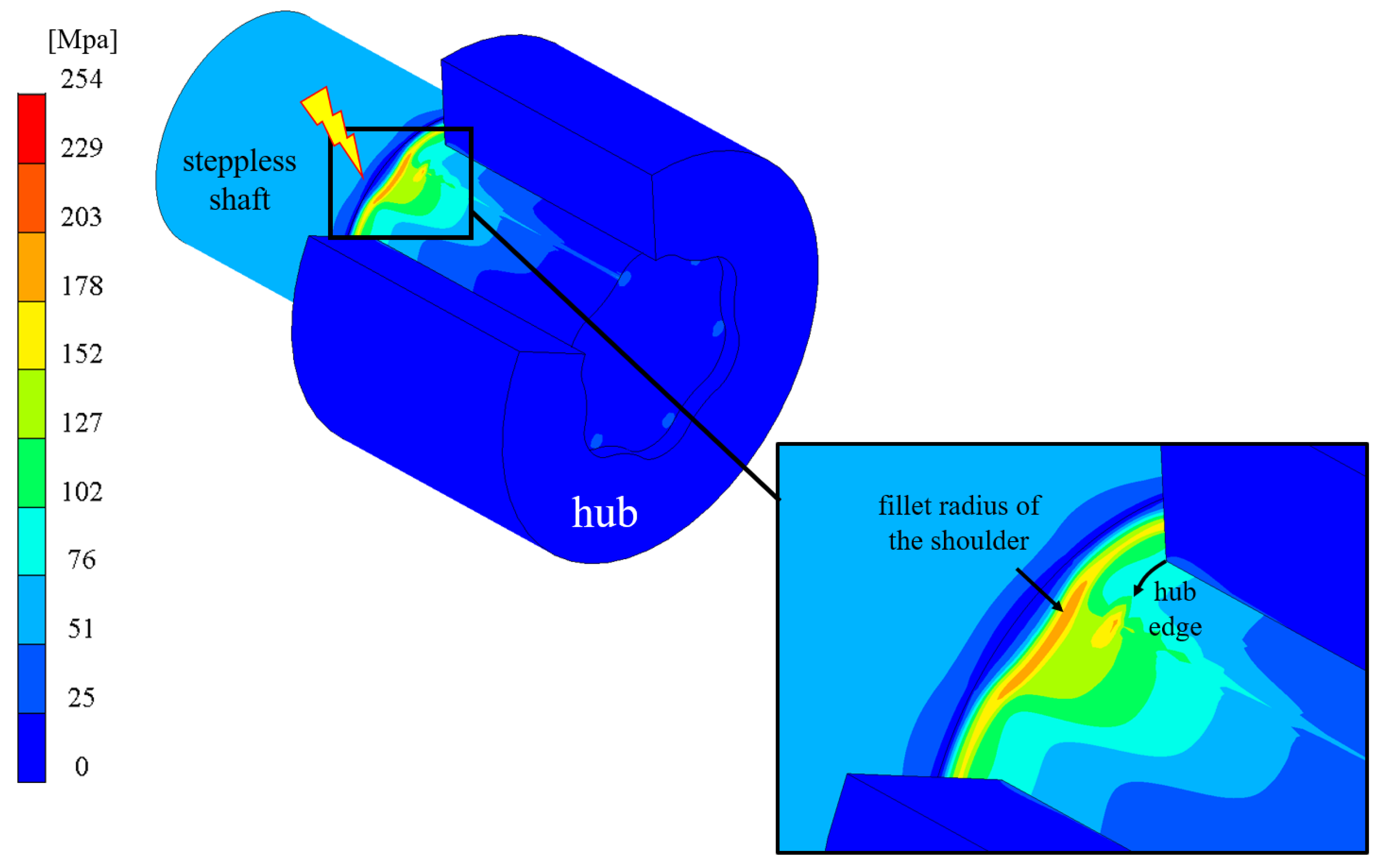
Figure 9.
Axial curve of the maximum principal stress due to the maximum stress in the rounding radius of the shaft shoulder (left) and maximum stress as a function of variable distances a of the hub edge from the shaft shoulder (right); = 600 Nm, linear–elastic material behaviour, idealised zero clearance.
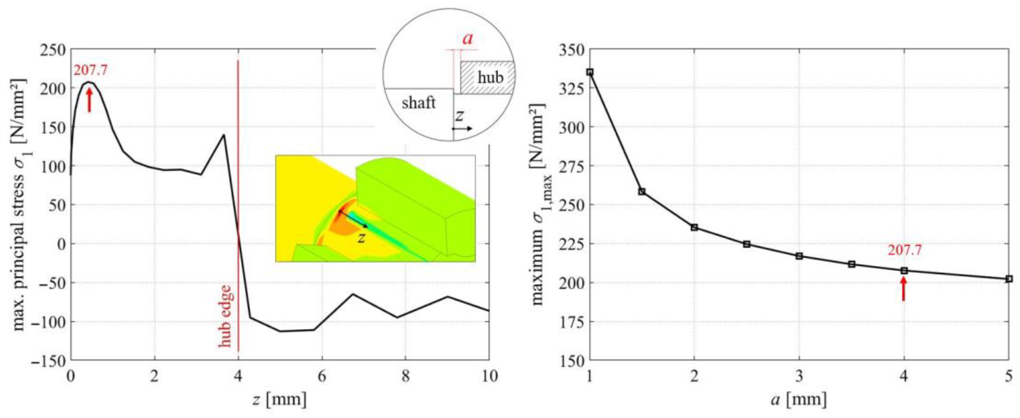
Figure 10.
Comparison of the stress curves between two driver heads directly at the hub edge (left) and in the fillet radius of the shaft shoulder (right); = 600 Nm, linear–elastic material behaviour, idealised zero clearance, distance a = 4 mm.
Figure 10.
Comparison of the stress curves between two driver heads directly at the hub edge (left) and in the fillet radius of the shaft shoulder (right); = 600 Nm, linear–elastic material behaviour, idealised zero clearance, distance a = 4 mm.
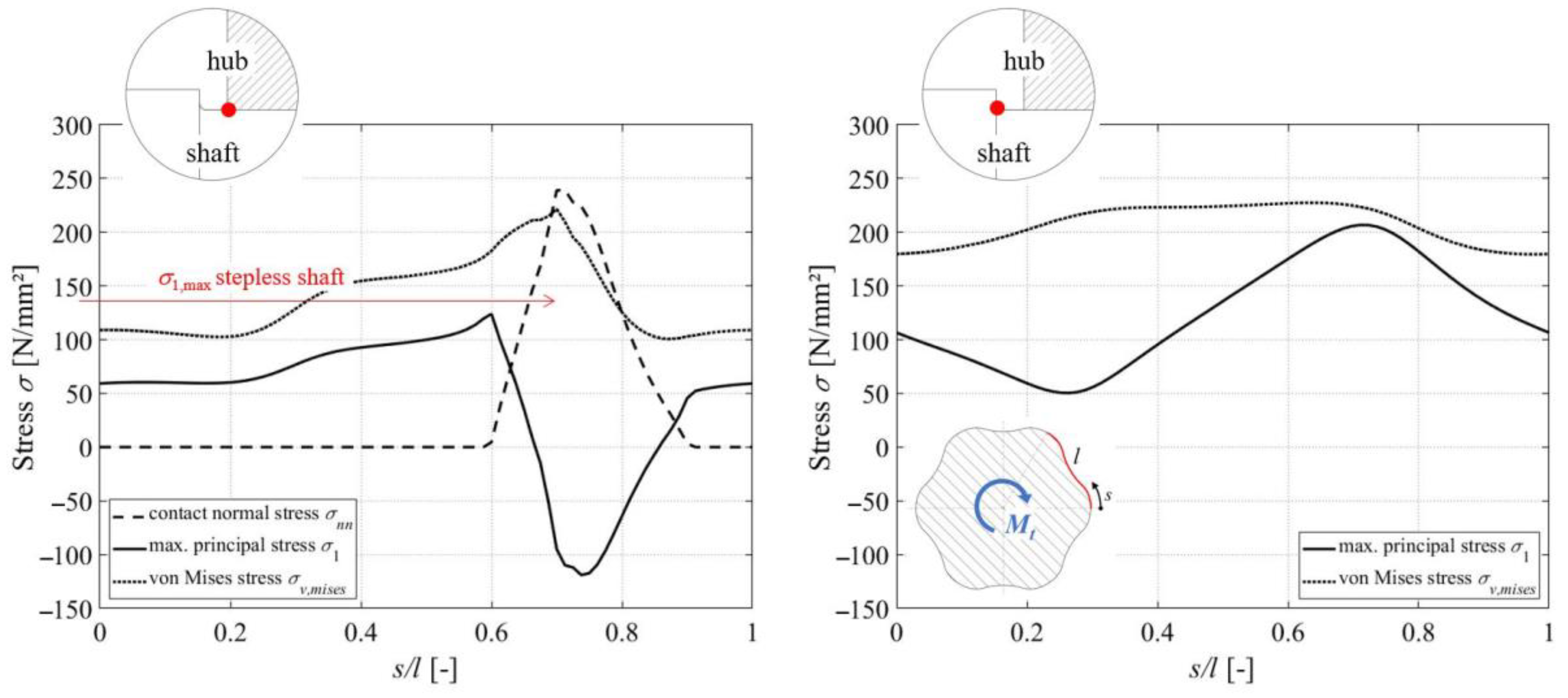
Figure 11.
Electromechanical unbalanced-mass test rig for generating alternating and pulsating torsional loads.
Figure 11.
Electromechanical unbalanced-mass test rig for generating alternating and pulsating torsional loads.
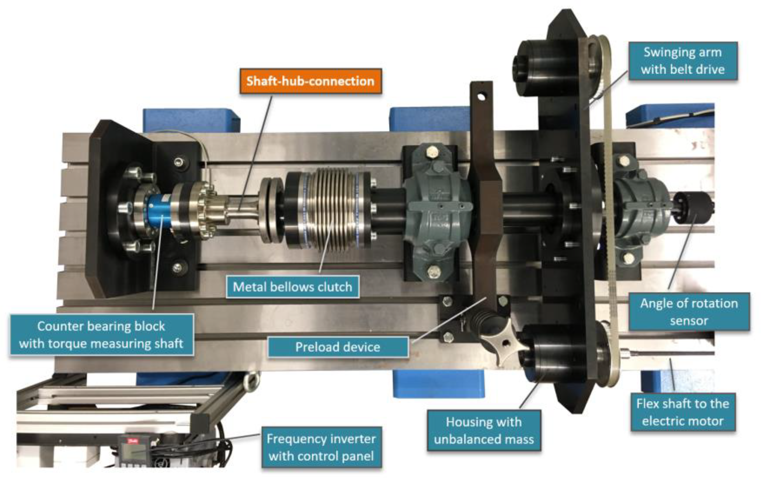
Figure 12.
Specification of the hub geometry and position in conjunction with a stepless (left) and stepped (right) M6-profiled shaft for the dynamic component tests.
Figure 12.
Specification of the hub geometry and position in conjunction with a stepless (left) and stepped (right) M6-profiled shaft for the dynamic component tests.

Figure 13.
Fatigue strength (left) and notch coefficient βτ (right) of the stepless M6-profiled shaft in direct comparison with the stepped shaft and depiction of the influences of the manufacturing technology, fitting, and material.
Figure 13.
Fatigue strength (left) and notch coefficient βτ (right) of the stepless M6-profiled shaft in direct comparison with the stepped shaft and depiction of the influences of the manufacturing technology, fitting, and material.
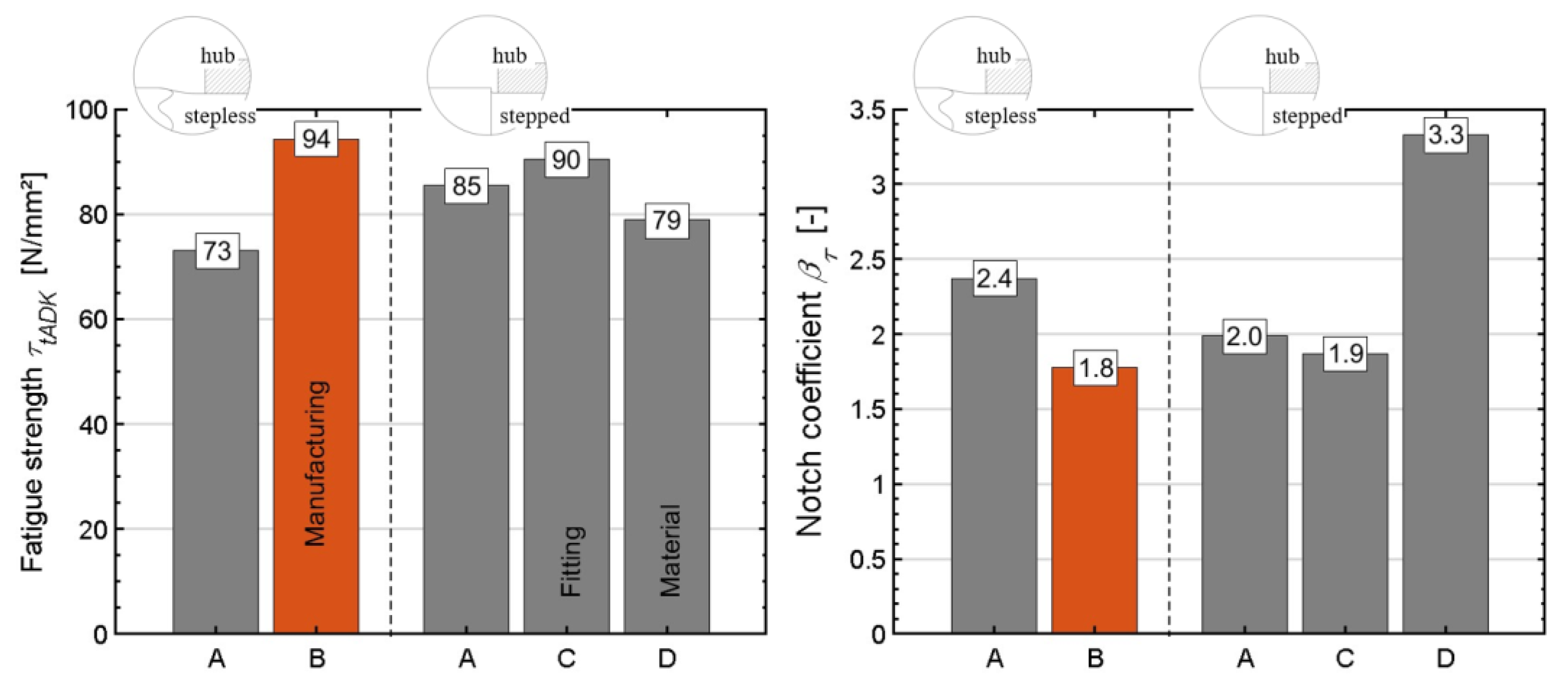
Figure 14.
Initial crack in the area of the friction-corrosive damaged zone (left) and further growth of the friction fatigue fracture (centre) of the stepless M6-profile shaft under a torsional swelling load; purely mechanical stress crack initiation in the fillet of the shaft shoulder when the hub is positioned at a distance of a = 4 mm from the shaft shoulder (right).
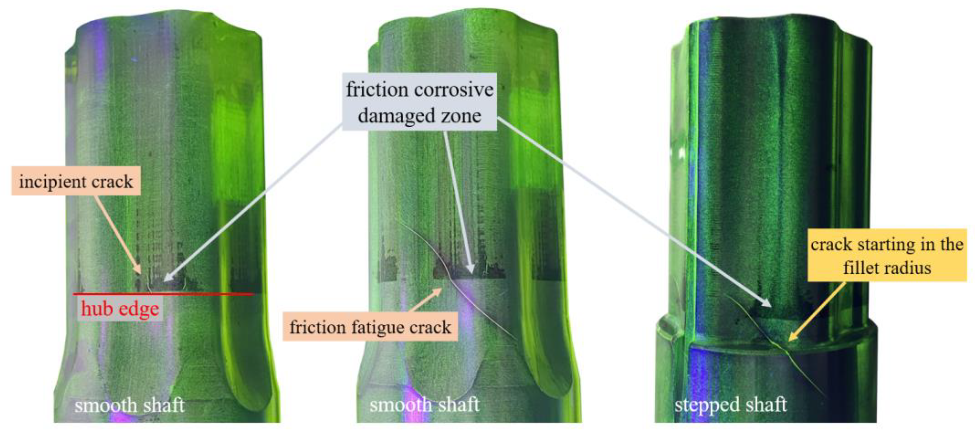
Figure 15.
Hypotrochoidal profile contour standardised according to DIN 3689-1 (left) and epitrochoidal profile (right), both with n = 3 corners and identical tip diameters of = 40 mm.
Figure 15.
Hypotrochoidal profile contour standardised according to DIN 3689-1 (left) and epitrochoidal profile (right), both with n = 3 corners and identical tip diameters of = 40 mm.
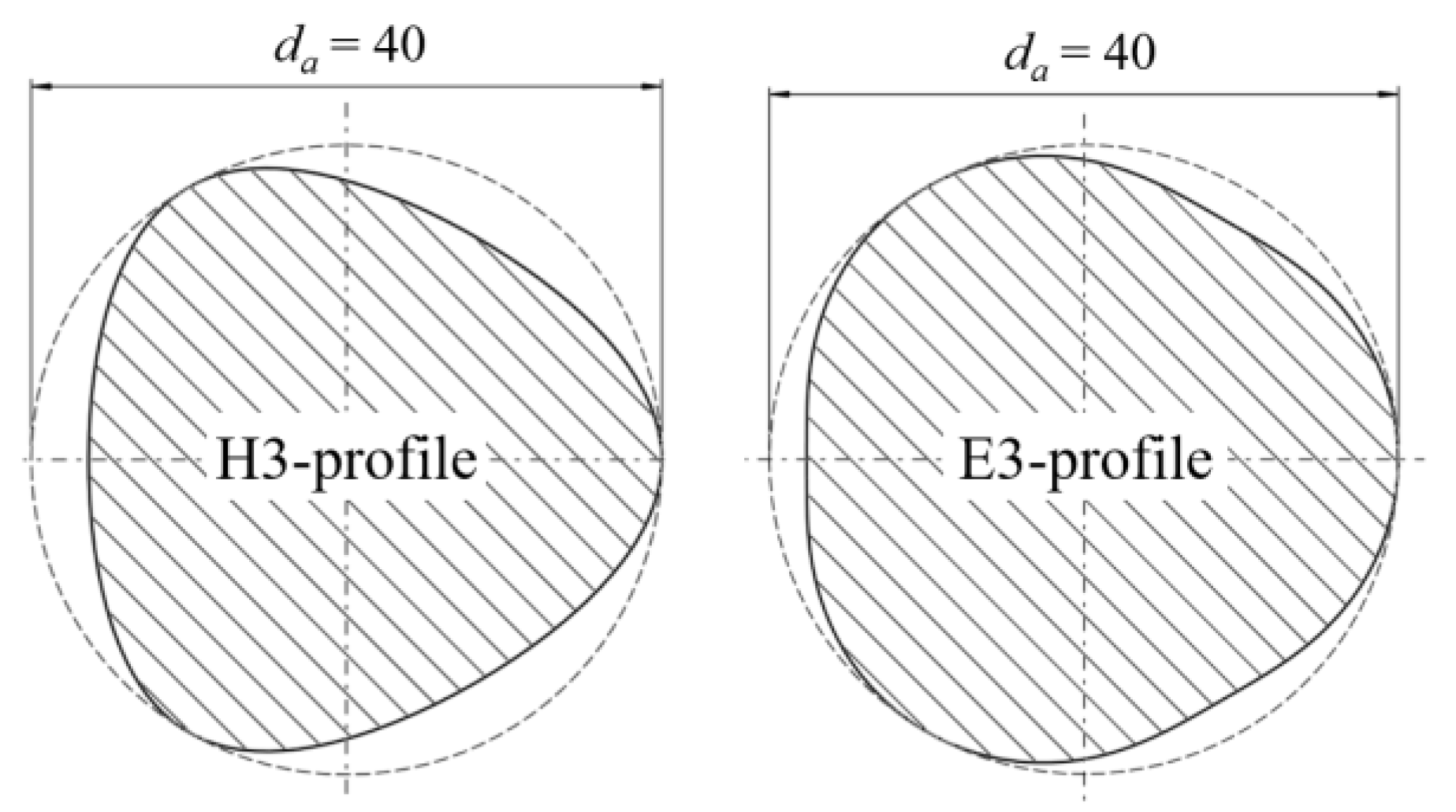
Figure 16.
Fatigue strength (left) and notch coefficient βτ (right) of the H3- and E3- profiles, determined on the basis of a connection with a stepless shaft.
Figure 16.
Fatigue strength (left) and notch coefficient βτ (right) of the H3- and E3- profiles, determined on the basis of a connection with a stepless shaft.
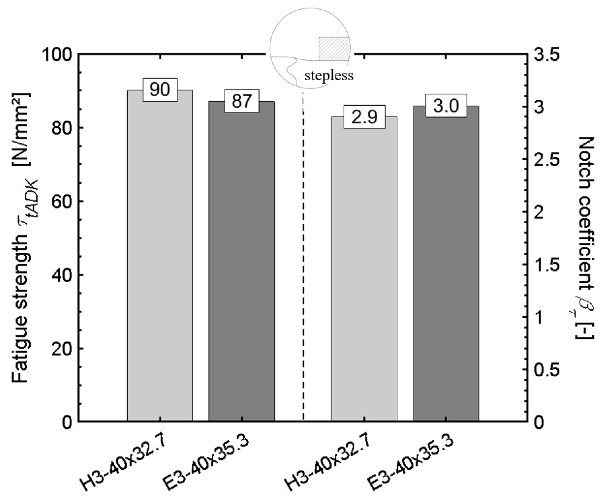
Figure 17.
Influence of the shaft shoulder on the achieved number of load cycles N for a given torsional stress amplitude for the H3-profile (left) and E3-profile (right); breaks are marked with “x” and run-outs are marked with “0”.
Figure 17.
Influence of the shaft shoulder on the achieved number of load cycles N for a given torsional stress amplitude for the H3-profile (left) and E3-profile (right); breaks are marked with “x” and run-outs are marked with “0”.

Table 1.
Variants of the M6-profiled shaft–hub connections for the component tests.
| Labelling | Material of the Shaft | Manufacturing Process Used to Create the Shaft | Fitting |
|---|---|---|---|
| A | C45R+N | Oscillating non-circular turning | Clearance fit |
| B | C45R+N | Hobbing | Clearance fit |
| C | C45R+N | Oscillating non-circular turning | Interference fit |
| D | 42CrMoS4+QT | Oscillating non-circular turning | Clearance fit |
Table 2.
Profile parameters of the E3- and H3-profiles.
| Profile Type | H-Profile | E-Profile |
|---|---|---|
| Nominal profile radius r | 18.181 mm | 18.824 mm |
| Eccentricity e | 1.818 mm | 1.177 mm |
| Number of corners n | 3 | 3 |
| Tip diameter da | 40.00 mm | 40.00 mm |
| Root diameter di | 32.73 mm | 35.29 mm |
Disclaimer/Publisher’s Note: The statements, opinions and data contained in all publications are solely those of the individual author(s) and contributor(s) and not of MDPI and/or the editor(s). MDPI and/or the editor(s) disclaim responsibility for any injury to people or property resulting from any ideas, methods, instructions or products referred to in the content. |
© 2024 by the authors. Licensee MDPI, Basel, Switzerland. This article is an open access article distributed under the terms and conditions of the Creative Commons Attribution (CC BY) license (https://creativecommons.org/licenses/by/4.0/).
Share and Cite
MDPI and ACS Style
Ziaei, M.; Selzer, M.; Sommer, H. Influence of a Shaft Shoulder on the Torsional Load-Bearing Behaviour of Trochoidal Profile Contours as Positive Shaft–Hub Connections. Eng 2024, 5, 834-850. https://doi.org/10.3390/eng5020045
AMA Style
Ziaei M, Selzer M, Sommer H. Influence of a Shaft Shoulder on the Torsional Load-Bearing Behaviour of Trochoidal Profile Contours as Positive Shaft–Hub Connections. Eng. 2024; 5(2):834-850. https://doi.org/10.3390/eng5020045
Chicago/Turabian StyleZiaei, Masoud, Marcus Selzer, and Heiko Sommer. 2024. "Influence of a Shaft Shoulder on the Torsional Load-Bearing Behaviour of Trochoidal Profile Contours as Positive Shaft–Hub Connections" Eng 5, no. 2: 834-850. https://doi.org/10.3390/eng5020045