
Cylindrical Sandwich Shells for Civil Engineering Applications †


1
Department of Mechanical Engineering, CEMMPRE, ARISE, University of Coimbra, 3030-788 Coimbra, Portugal
2
Unidade Departamental de Engenharias, Escola Superior de Tecnologia de Abrantes, Instituto Politécnico de Tomar, Rua 17 de Agosto de 1808 S/N, 2200-370 Abrantes, Portugal
3
Grupo de Elasticidad y Resistencia de Materiales, Escuela Técnica Superior de Ingeniería, Universidad de Sevilla, Camino Descubrimientos, 41092 Sevilla, Spain
4
Escuela Politécnica Superior, Universidad de Sevilla, C/ Virgen de África, 7, 41011 Sevilla, Spain
*
Author to whom correspondence should be addressed.
†
Presented at the 1st International Online Conference on Buildings, 24–26 October 2023; Available online: https://iocbd2023.sciforum.net/ .
Eng. Proc. 2023, 53(1), 14; https://doi.org/10.3390/IOCBD2023-15196
Published: 24 October 2023
(This article belongs to the Proceedings of The 1st International Online Conference on Buildings)
Abstract
:The literature is not abundant with mechanical characterizations of cylindrical shells for civil engineering applications, especially in terms of impact response. In this context, this study intends to evaluate the impact response of cylindrical sandwich shells produced by various types of fibers. Analysis was performed on three alternative configurations: carbon fibers only, carbon fibers and glass, and carbon fibers and basalt. All configurations were tested for static and impact strength. It was concluded that the constituents of the cylindrical sandwich shells are determinants of both static and impact strength. In terms of compressive properties, the lowest displacement (4.4 mm) and highest compressive strength (873 N) and stiffness (354 N/mm) are attributed to configuration 6C. However, the incorporation of basalt fibers decreased these properties to the lowest values, and reductions of 22% and 44% were found for the compressive strength and stiffness, respectively, while the displacement increased by around 66%. On the other hand, in terms of impact, significant benefits were achieved with the introduction of glass fibers. Compared with configurations 6C and 2C+2B+2C, for instance, the elastic recuperation was 25% and 64.6% higher, respectively.
1. Introduction
Every day, it is noticeable that traditional materials are being replaced by composite materials, including in the civil engineering sector, because of their high specific stiffness and strength, adjustable properties, excellent static and dynamic properties, and good corrosion resistance.
In this particular sector (civil engineering applications), they are used both as structural reinforcement and in non-structural applications such as geotextiles. However, because most of the published studies focus essentially on the advantages obtained with these materials, the literature is still lacking regarding their characterization for structural purposes. An example of this is their response to impact, a loading mode to which they are very sensitive. Low-velocity impacts, for example, are frequent in service or during maintenance procedures, are challenging to detect, and have a significant effect on residual mechanical performance [1].
In terms of structural integrity, the literature reports some studies in terms of damage mechanisms [2,3,4], residual compression after impact [5], multi-impacts [6], and environmental effects [7], but these mainly focus on composite plates. However, while far less common, investigations on cylindrical shells are extremely important given the current theories regarding complex structures.
Therefore, considering the need for this knowledge, this study aims to analyze the impact response of cylindrical sandwich shells for civil engineering applications. For this purpose, cylindrical shells with the same number of layers but involving different types of fibers are considered.
2. Experimental Procedure
By using a hand lay-up process, cylindrical sandwich shells were manufactured using six layers of bi-directionally woven fabrics and an SR1500 epoxy resin with SD2503 hardener (both provided by Sicomin, Chateauneuf les Martigues, France). Stacking sequences of 6C; 2C+2G+2C and 2C+2B+2C were analyzed. The numbers quantify the layers and the letters the type of fibers used (C = carbon fibers (taffeta with 160 g/cm2), G = glass fibers (taffeta with 205 g/cm2), and B = basalt fibers (basalt grid with 11.5 g/cm2)). This system was then subjected to a pressure of 0.5 mbar for 9 h and placed within a vacuum bag for 24 h to remove any air bubbles and guarantee a constant fiber volume fraction and uniform laminate thickness. After that, post-curing took place for 16 h at 60 °C using an oven. The production procedure and the sample geometry are displayed in Figure 1.
The drop-weight-testing machine IMATEK-IM10, which is described in [8], was used for low-velocity impact tests. A 10 mm impactor with a mass of 2.826 kg was used to strike the center of the specimens with free support at the curved edges and bi-supported edges at the other sides. The samples were tested with an energy of 5 J, which caused apparent damage but no perforation. The ASTM D7136 standard [9] was followed in performing these impact tests.
The same support and loading nose were used for bending tests on Shimadzu AG-100 universal testing equipment. Five samples were used for each configuration at room temperature and with a displacement rate of 3 mm/min.
3. Results and Discussion
Initially, static bending tests were performed on cylindrical sandwich shells for a better understanding of their impact response. In this context, Figure 2 shows typical force–displacement curves, where a linear region is perceptible in all curves. It is also noticeable that the maximum static strength and stiffness are obtained in the configuration involving only carbon fibers (6C), while the lowest strength and stiffness are associated with the sandwiches, whose values are very similar.
Table 1 presents the average compressive properties, where the stiffness is determined by the slope of the force–displacement curves in the linear region and the displacement values for the maximum compressive force. It is possible to observe that the highest compression force occurs for the cylindrical shells produced only with carbon fibers (873 N), while for sandwiches, the values obtained are about 17.3% lower. In fact, there is a difference of around 5.8% between the average values obtained for the sandwiches, but considering the dispersion, this difference is insignificant, and the maximum compressive force can be considered very similar. The same is observed for stiffness, where the highest value is 354 N/mm, and the decrease for the sandwiches is around 42.7%. The opposite is observed for the displacement, where the highest values occur for the sandwiches and are 63.3% higher. The fibers’ inherent mechanical characteristics and related damage mechanisms explain what is observed [10]. In fact, the glass fiber composites fail on the tension side, while the carbon fiber composites primarily fail on the compression side [11].
In terms of impact response, Figure 3 shows typical force–time curves obtained from the impact tests, which present a similar profile to those described in the literature [10,12]. The observed oscillations are caused by the vibrations of the specimen and depend on both the stiffness and mass of the specimen and impactor [13,14]. Furthermore, it is noteworthy that all configurations are characterized by a force increase up to a maximum value, followed by a drop after the force peak. This is more evident for the sandwiches, while for the cylindrical shells containing only carbon (6C), after some decrease, the force remains practically constant for some period of time, and only then does it decrease significantly. This curve, different from the others, reveals that, although the impact does not cause perforation, it is responsible for introducing more significant damage than in the sandwiches. In fact, brittle failures are characteristic of carbon fibers, which are fragile when compressed or exposed to impact loads [11].
Regarding the force–displacement and energy–time curves, Figure 4 shows the respective responses of the different materials. In the first case, the force–displacement curves are very similar to the force–time curves, which are characterized by an increase in force up to a maximum value and a subsequent decrease, with the two distinct behaviors reported above. Therefore, these curves confirm that cylindrical shells involving only carbon fibers (6C) suffer more severe damage than sandwiches. The impactor strikes the specimens and rebounds, indicating that the impact energy is insufficient to enable full penetration, as may be inferred from all energy–time curves. In this instance, the start of the plateau denotes the loss of contact between the striker and the specimen and corresponds to the energy absorbed by the specimen [4]. Therefore, for an impact energy of 5 J, it is noted that the sandwich involving carbon and glass fibers (2C+2G+2C) is the one that absorbs less energy, while the other sandwich (2C+2B+2C) is the one that absorbs more energy.
Table 2 lists the average values and corresponding standard deviations for peak force, maximum displacement, and elastic recuperation in order to quantify all the evidence presented previously.
It is evident from Table 2 that the maximum force for configurations 6C (0.924 kN) and 2C+2G+2C (0.916 kN) is identical. In this case, the difference is less than 1%, but it increases considerably to around 16% compared with the basalt and carbon sandwich (2C+2B+2C). This can be explained by the different stiffness values reported in Table 1. The opposite behavior is observed for the maximum displacement, where configuration 6C presents the smallest value, and configuration 2C+2B+2C has the largest displacement with a difference of around 34.6%. The literature supports these findings, which show that stiffer structures produce greater impact forces, smaller deflections/displacements, and shorter contact times [12]. Finally, in terms of elastic recuperation, the lowest value is obtained for configuration 2C+2B+2C (with 1.3 J), followed by configuration 6C (31.5% higher) and 2C+2G+2C (64.6% higher). Consequently, greater damage is expected when the elastic recuperation decreases. Although the largest damage area is on the upper surface of the cylindrical shells, the damage starts at the top ply and spreads to the bottom layers [10].
4. Conclusions
The main goal of this study was to analyze the impact response of cylindrical sandwich shells for civil engineering applications involving different types of fibers. The conclusion that the shell’s components affect both the static and impact performance was possible to obtain. In terms of static properties, for example, the highest strength and stiffness were obtained for cylindrical shells produced only with carbon fibers (6C), while the displacement was the lowest. However, the opposite properties (lower strength and stiffness while the displacement is larger) were obtained when basalt fibers were included in the sandwich (2C+2B+2C). Regarding the impact strength, the benefits achieved with the introduction of glass fibers to the detriment of basalt fibers are significant. In this case, the glass fibers were responsible for the highest restored energy and the basalt fibers for the lowest elastic response of the specimens.
Author Contributions
Conceptualization, P.N.B.R. and C.A.C.P.C.; methodology, P.N.B.R. and C.A.C.P.C.; formal analysis, P.N.B.R., C.A.C.P.C. and L.M.F.; investigation, P.N.B.R., C.A.C.P.C. and L.M.F.; resources, P.N.B.R. and C.A.C.P.C.; writing—original draft preparation, P.N.B.R., L.M.F. and C.A.C.P.C.; writing—review and editing, P.N.B.R., L.M.F. and C.A.C.P.C. All authors have read and agreed to the published version of the manuscript.
Funding
This research was sponsored by national funds through FCT-Fundação para a Ciência e a Tecnologia under projects UIDB/00285/2020 and LA/P/0112/2020.
Institutional Review Board Statement
Not applicable.
Informed Consent Statement
Not applicable.
Data Availability Statement
The data presented in this study are available upon request from the corresponding authors.
Conflicts of Interest
The authors declare no conflict of interest.
References
- de Moura, M.F.S.F.; Marques, A.T. Prediction of low velocity impact damage in carbon-epoxy laminates. Compos. Part A Appl. Sci. Manuf. 2002, 33, 361–368. [Google Scholar] [CrossRef]
- Richardson, M.O.W.; Wisheart, M.J. Review of low-velocity impact properties of composite materials. Compos. Part A Appl. Sci. Manuf. 1996, 27, 1123–1131. [Google Scholar] [CrossRef]
- Río, T.G.; Zaera, R.; Barbero, E.; Navarro, C. Damage in CFRPs due to low velocity impact at low temperature. Compos. Part B-Eng. 2005, 36, 41–50. [Google Scholar] [CrossRef]
- Aktas, M.; Atas, C.; Icten, B.M.; Karakuzu, R. An experimental investigation of the impact response of composite laminates. Compos. Struct. 2009, 87, 307–313. [Google Scholar] [CrossRef]
- Kulkarni, M.D.; Goel, R.; Naik, N.K. Effect of back pressure on impact and compression after-impact characteristics of composites. Compos. Struct. 2011, 93, 944–951. [Google Scholar] [CrossRef]
- Reis, P.N.B.; Sousa, P.; Ferreira, L.M.; Coelho, C.A.C.P. Multi-impact response of semicylindrical composite laminated shells with different thicknesses. Compos. Struct. 2023, 310, 116771. [Google Scholar] [CrossRef]
- Mortas, N.; Er, O.; Reis, P.N.B.; Ferreira, J.A.M. Effect of corrosive solutions on composites laminates subjected to low velocity impact loading. Compos. Struct. 2014, 108, 205–211. [Google Scholar] [CrossRef]
- Amaro, A.M.; Reis, P.N.B.; Magalhães, A.G.; de Moura, M.F.S.F. The Influence of the boundary conditions on low-velocity impact composite damage. Strain 2011, 47, e220–e226. [Google Scholar] [CrossRef]
- ASTM-D7136; Standard Test Method for Measuring the Damage Resistance of a Fiber Reinforced Polymer Matrix Composite to a Drop-Weight Impact Event. ASTM International: West Conshocken, PA, USA, 2007.
- Coelho, C.A.C.P.; Navalho, F.V.P.; Reis, P.N.B. Impact response of laminate cylindrical shells. Frat. Integrità Strutt. 2019, 48, 411–418. [Google Scholar] [CrossRef]
- Giancaspro, J.W.; Papakonstantinou, C.G.; Balaguru, P.N. Flexural response of inorganic hybrid composites with E-glass and carbon fibers. J. Eng. Mater. Technol. 2010, 132, 021005-1–021005-8. [Google Scholar] [CrossRef]
- Reis, P.N.B.; Coelho, C.A.C.P.; Navalho, F.V.P. Impact Response of Composite Sandwich Cylindrical Shells. Appl. Sci. 2021, 11, 10958. [Google Scholar] [CrossRef]
- Schoeppner, G.A.; Abrate, S. Delamination threshold loads for low velocity impact on composite laminates. Compos. Part A Appl. Sci. Manuf. 2000, 31, 903–915. [Google Scholar] [CrossRef]
- Belingardi, G.; Vadori, R. Low velocity impact of laminate Glass-Fiber-Epoxy matrix composite materials plates. Int. J. Impact Eng. 2002, 27, 213–229. [Google Scholar] [CrossRef]
Figure 1.
(a) Process of manufacturing. (b) Specimens’ geometry and dimensions in mm.
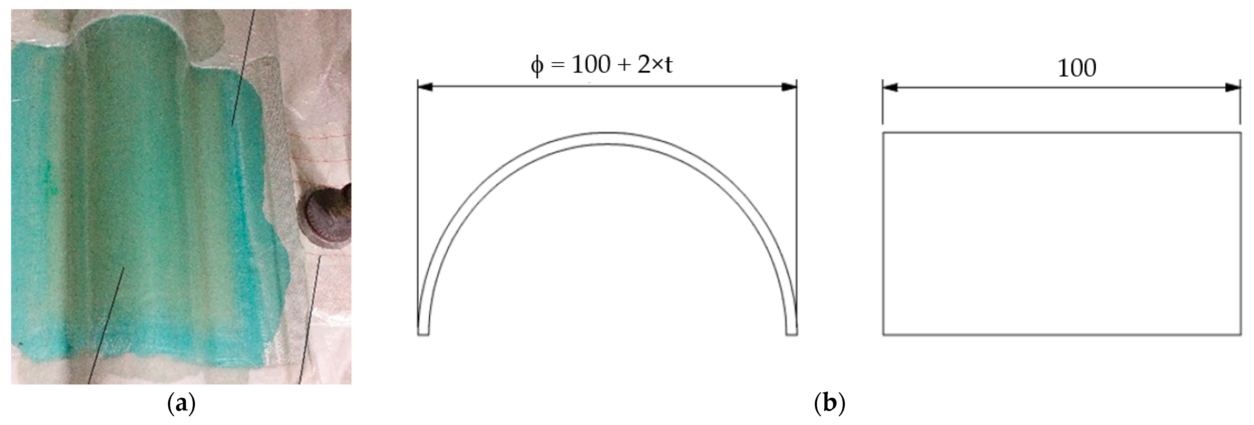
Figure 2.
Force–time curves for the repeated low-velocity impacts.

Figure 3.
Typical force–time curves obtained from low-velocity impacts.
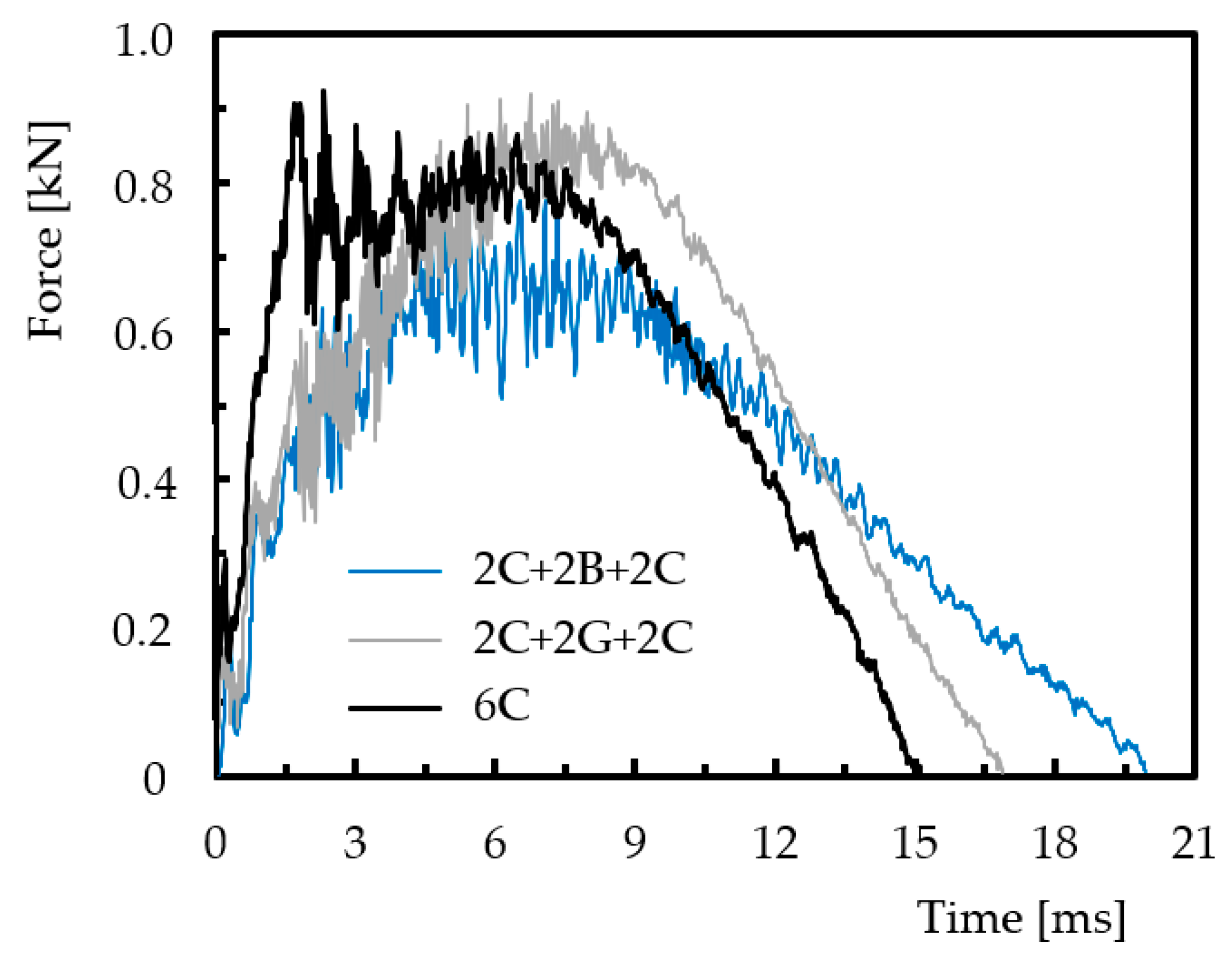
Figure 4.
(a) Typical force–displacement curves obtained from low-velocity impacts; (b) typical energy–time curves obtained from low-velocity impacts.
Figure 4.
(a) Typical force–displacement curves obtained from low-velocity impacts; (b) typical energy–time curves obtained from low-velocity impacts.


Table 1.
Compressive static properties.
| Cylindrical Shells | Maximum Force (N) | Displacement at Max. Force (mm) | Stiffness (N/mm) | |||
|---|---|---|---|---|---|---|
| Average | Std. | Average | Std. | Average | Std. | |
| 6C | 873 | 121 | 4.4 | 1.0 | 354 | 41 |
| 2C+2G+2C | 722 | 184 | 7.1 | 1.9 | 203 | 54 |
| 2C+2B+2C | 680 | 201 | 7.3 | 1.4 | 198 | 39 |
Table 2.
Impact properties.
| Cylindrical Shells | Peak Force (kN) | Max Displacement (mm) | Elastic Recuperation (J) | |||
|---|---|---|---|---|---|---|
| Average | Std. | Average | Std. | Average | Std. | |
| 6C | 0.924 | 0.12 | 7.8 | 1.9 | 1.71 | 0.91 |
| 2C+2G+2C | 0.916 | 0.21 | 9.5 | 3.1 | 2.14 | 0.98 |
| 2C+2B+2C | 0.774 | 0.26 | 10.5 | 0.8 | 1.30 | 0.72 |
Disclaimer/Publisher’s Note: The statements, opinions and data contained in all publications are solely those of the individual author(s) and contributor(s) and not of MDPI and/or the editor(s). MDPI and/or the editor(s) disclaim responsibility for any injury to people or property resulting from any ideas, methods, instructions or products referred to in the content. |
© 2023 by the authors. Licensee MDPI, Basel, Switzerland. This article is an open access article distributed under the terms and conditions of the Creative Commons Attribution (CC BY) license (https://creativecommons.org/licenses/by/4.0/).
Share and Cite
MDPI and ACS Style
Reis, P.N.B.; Coelho, C.A.C.P.; Ferreira, L.M. Cylindrical Sandwich Shells for Civil Engineering Applications. Eng. Proc. 2023, 53, 14. https://doi.org/10.3390/IOCBD2023-15196
AMA Style
Reis PNB, Coelho CACP, Ferreira LM. Cylindrical Sandwich Shells for Civil Engineering Applications. Engineering Proceedings. 2023; 53(1):14. https://doi.org/10.3390/IOCBD2023-15196
Chicago/Turabian StyleReis, Paulo N. B., Carlos A. C. P. Coelho, and Luis M. Ferreira. 2023. "Cylindrical Sandwich Shells for Civil Engineering Applications" Engineering Proceedings 53, no. 1: 14. https://doi.org/10.3390/IOCBD2023-15196