Proceeding Paper

Quantifying Clinician-Controlled Preload in Dental Implants: Analysis of Manual Tightening Torque and Complication Rates †

1
Department of Engineering, University of Messina, Contrada di Dio, 98166 Messina, Italy
2
Department of Biomedical and Dental Sciences and Morphological and Functional Imaging, University of Messina, Via Consolare Valeria 1, 98100 Messina, Italy
3
Department of Prosthodontics, Dr. D.Y. Patil Dental College and Hospital, Dr. D.Y. Patil Vidyapeeth, Pimpri, Pune 411018, Maharashtra, India
4
Multidisciplinary Department of Medical-Surgical and Dental Specialties, Second University of Naples, 80100 Naples, Italy
*
Author to whom correspondence should be addressed.
Presented at the 4th International Electronic Conference on Applied Sciences, 27 October–10 November 2023; Available online: https://asec2023.sciforum.net/.
Eng. Proc. 2023, 56(1), 252; https://doi.org/10.3390/ASEC2023-15955
Published: 9 November 2023
(This article belongs to the Proceedings of The 4th International Electronic Conference on Applied Sciences)

Abstract

:
The calculation of manual tightening torque applied by clinicians plays a critical role in achieving optimal preload for dental implants. However, there is a research gap when it comes to understanding the specific calculus involved in this process. This study aims to address this gap by analyzing the bending and torsional moments during manual tightening torque application by physicians of various specialties and genders. Additionally, the rates of early complications associated with clinician-calculated preload will be evaluated. The findings of this study will contribute to enhancing the understanding of clinician-controlled preload and guide future practices for successful dental implant outcomes.

1. Introduction

Since the inception of dentistry, a primary goal has been the restoration of chewing function and tooth replacement. The confluence of bioengineering and dental applications has witnessed substantial advancements in recent years, particularly in sensor technologies and computational methodologies. Many studies have contributed to this burgeoning body of knowledge, addressing key aspects such as force sensing, haptic feedback, automation, and the clinical implementation of these technologies. One seminal work, titled “A Comparison of Force Sensing for Applications in Prosthetic Haptic Feedback”, undertakes a comprehensive analysis of various sensor designs, with a particular focus on load cells for prosthetic applications [1]. The investigation presents crucial insights into force requirements through its experiments on laboratory-standard load cell sensor technologies, thereby facilitating a deeper understanding of manual tightening torque calculations in dental implants. Within the context of low-cost sensor systems employing Arduino, the study “3D Printed Low-Cost Force-Torque Sensors” proposes an innovative approach by incorporating off-the-shelf optical sensors into 3D-printed components [2]. The paper elaborates on Arduino firmware and ROS (Robotic Operating System)-based drivers, presenting a feasible trajectory for developing cost-effective torque sensors tailored for dental applications. Another notable study, “Arduino-based Automated Dosage Prescriptor using Load Cell”, explores the utility of an Arduino board interfaced with an HX711 ADC and a load cell for automating anesthesia dosage administration [3]. Although primarily targeted at anesthesiology, this study establishes a precedent for leveraging Arduino boards and load cells in medical contexts for precise measurements, a concept potentially extendable to preload calculations in dental implants. Expanding the array of cost-efficient, Arduino-based measurement tools, the paper “Open-Source Digitally Replicable Lab-Grade Scales” delves into the development of an easily replicable, open-source, lab-grade digital scale using an Arduino Nano and 3D-printed components [4]. Although initially intended for laboratory settings, the meticulous detail, precision and accuracy revealed in this study open up promising avenues for exact mass and force measurements, which are highly relevant for preload calculations in dental implants. A comprehensive review entitled “Prototyping with Arduino” [5] scrutinizes the challenges and opportunities inherent to Arduino-based projects. The review highlights the platform’s flexibility and suitability for individuals with limited programming skills. Given the burgeoning interest in medical applications of Arduino for prototyping, this review furnishes invaluable context and guidelines for developing Arduino-centric systems for dental implant torque measurement. As scientific advancements have unfolded, the development of dental implants has revolutionized this field by accelerating the process of osseointegration and significantly enhancing the quality of life for patients. Initially, the focus was on achieving robust osseointegration to ensure implants possessed both mechanical strength and long-term stability within the bone. Titanium, renowned for its mechanical properties and compatibility with human bone, has played a pivotal role in orthodontic prostheses and is extensively documented in the literature. However, in recent years, attention has shifted towards soft tissue integration, introducing greater complexity in both design techniques and material selection. This includes the use of composites [6,7] and 3D biomedical metal materials produced through Additive Manufacturing techniques [8]. Dental implantology has emerged as a widely adopted approach, offering comprehensive treatment options for both fully and partially edentulous patients [9,10]. While the long-term clinical success of dental implants is well established, it is intrinsically linked to adherence to proper surgical and prosthetic protocols. Despite generally high success rates, complications in implant-supported prostheses are not uncommon. These complications encompass a range of issues, including intraoperative challenges, bone loss, peri-implantitis, esthetic and phonetic concerns, and prosthetic biomechanical complications. Among these prosthetic complications, abutment screw loosening stands out as a prevalent and critical problem. The wrench, or torque wrench, is used to apply specific torque values to tighten the abutment screw, ensuring the stability and longevity of the dental implant. Several factors contribute to this issue, including insufficient preload, improper implant positioning, occlusal profile mismatch, variations in hex dimensions, poor adaptation of implant components, screw design flaws, excessive occlusal forces, and inadequate anti-rotation features [11,12,13,14]. The recommended torque values for abutment screw tightening largely fall within the range of 20 to 35 N/cm to mitigate screw loosening, with most implant manufacturers endorsing this range [15]. It is imperative to adhere to these specific recommendations, as diverging from the advised torque values may result in either insufficient clamping force or excessive torque, potentially leading to screw bending [15]. Studies also suggest that the definitive torque values could be influenced by various factors, including the screw head design, abutment screw material, and the use of lubricants, with a broader range of 10 to 35 N/cm being noted [16]. Additionally, a specific instance of a 25 N/cm torque value has been documented in practice while investigating reverse torque values of abutment screws [17]. While these investigations collectively represent significant strides in sensor technologies and Arduino-based systems, a distinct research gap remains in the calculations involved in the manual tightening torque application for dental implants. However, these antecedent studies lay a foundational framework upon which current research can build, particularly concerning the integration of Arduino boards and load cells for precise and cost-effective measurement systems. The aim of the forthcoming study is to develop a protocol for quantifying the torque applied to a dental implant. This will be achieved by employing a 3D-printed instrumented torque wrench specifically designed to measure the torque applied to the abutment screw of the dental implant.

2. Materials and Methods

A specific protocol has been established for calculating the preload applied to the dental implant, which is based on developing a device capable of measuring the force applied to the prosthesis. This device must be designed to be usable by both right-handed and left-handed individuals, thus ensuring that the measurement is independent of the subject undergoing the test. The device primarily consists of electronic and mechanical components. The mechanical part comprises the wrench, which is fabricated using additive manufacturing through the FDM process [11,15,16,17,18], while the electronic component consists of an HX711 load cell connected to an Arduino REV3 (Arduino srl, Monza, Italy).

2.1. Technical Implementation, Software, and Comprehensive Mathematical Framework

Developing and implementing our measurement system is the optimal solution for our specific dental implant preload optimization needs. The system’s architecture integrates selected hardware, specialized software algorithms, and a robust mathematical framework. This combination is specifically tailored to provide the highest levels of precision and reliability in torque measurement for our application.

2.1.1. Hardware Configuration

At the system’s core, we employ a strain gauge load cell meticulously calibrated and integrated into a Wheatstone bridge circuit. This intricate network of four resistors is specifically engineered to mitigate the influence of extraneous factors, such as temperature fluctuations and wire resistance, ensuring its role as a fundamental building block for achieving precise and high-resolution measurements. The strain gauge itself is meticulously crafted with a resistive wire, and its alteration in resistance, denoted as Δ R , is quantified using the following equation:
Δ R = R ( 1 + 2 ε + k ε ^ 2 )
Here, ε denotes strain and k is a non-linearity constant that becomes negligible under small deformations. The Wheatstone bridge’s analog signals are amplified by an HX711 Analog-to-Digital Converter (ADC, SparkFun Electronics, Niwot, CO, USA), which is outfitted with a Programmable Gain Amplifier (PGA). The ADC performs dual functions: digitizing the analog signals and pre-amplifying them, thus enhancing the signal-to-noise ratio and making the system resilient to electromagnetic interference. The HX711 is interfaced with an Arduino REV3 microcontroller board, equipped with an ATmega328P microprocessor (Atmel acquired by MICROCHIP INCORPORATED TECHNOLOGY, Chandler, AZ, USA) operating at a 16 MHz clock frequency and featuring a 32 KB Flash memory. This high-speed, two-wire synchronous serial communication protocol ensures data integrity and scalability, leaving ample GPIO pins on the Arduino board for future augmentations.

2.1.2. Software Infrastructure

The software framework operates on the Arduino IDE 1.8, with a specialized library dedicated to the HX711 ADC for seamless data acquisition. Written in C++, the source code contains essential functions for the system. For example, begin() initiates the load cell with predefined pins, while functions like read_average() and get_units() allow for meticulous data retrieval and calibration.

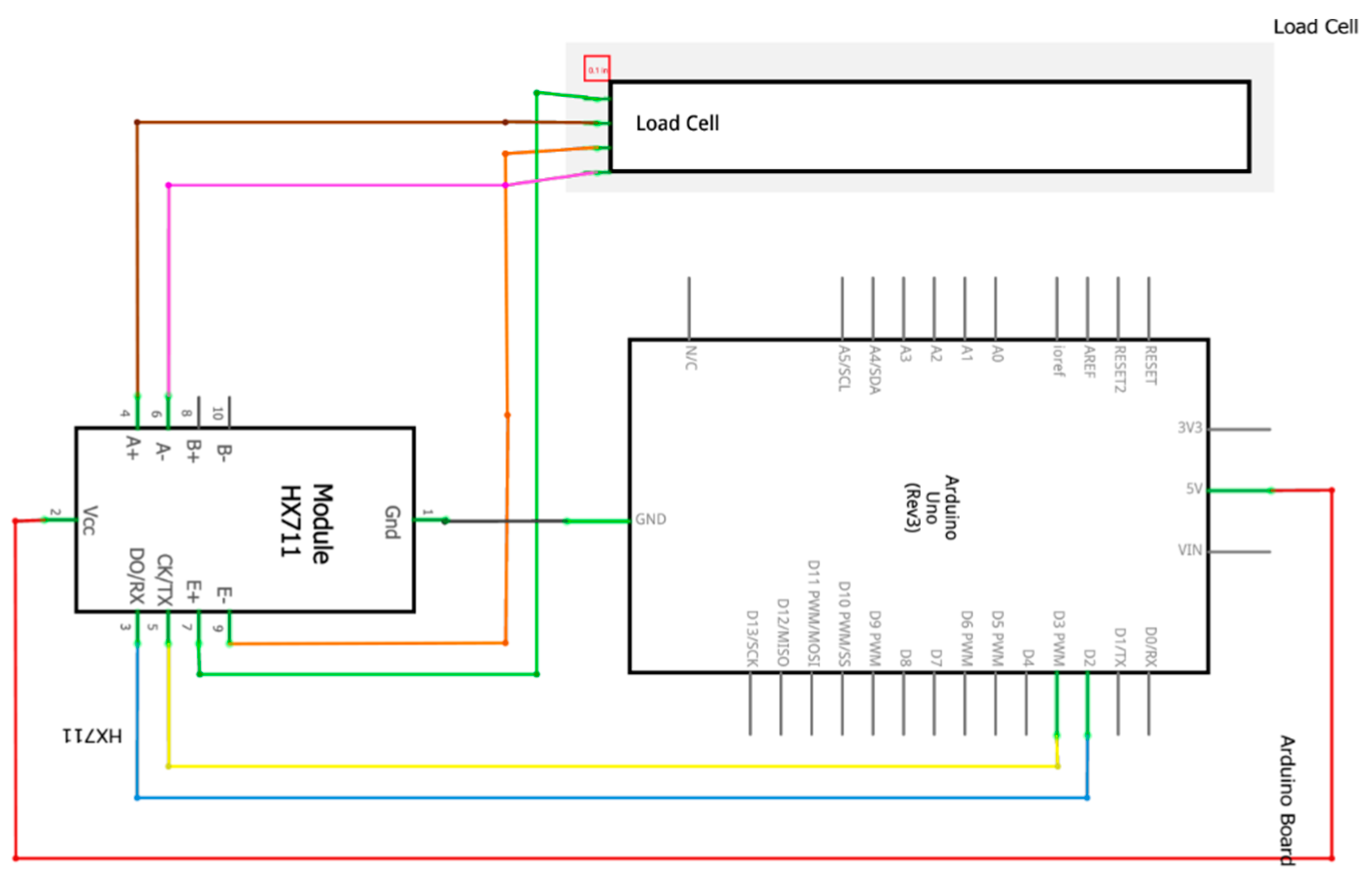
2.1.3. Wiring and Signal Pathways

The wiring schema has been meticulously designed for optimal signal integrity as follows:
  • E+ (Green) of the load cell connects to E+ of the HX711 and also to the Arduino GND.
  • E− (Orange) connects to E− of the HX711.
  • A− (Brown) connects to A− of the HX711.
  • A+ (Purple) connects to A+ of the HX711.
  • HX711 VCC is connected to Arduino 5V.
The TX and RX pins are connected to pins D2 and D3 on the Arduino board, respectively(Figure 1).
The system integrates a well-defined hardware architecture, specialized software algorithms, and a robust mathematical approach. This multidisciplinary integration has undergone meticulous calibration and testing to ensure that torque measurements meet the requisite levels of accuracy for our applications in the field of dental implants. Through the calibration process, coupled with algorithms that underpin the system’s logic, we can achieve measurements that closely align with industry standards and the specific requirements of our project. Additionally, the collected data are subjected to further statistical analyses to validate the system’s precision and provide a comprehensive understanding of the complexities associated with preload optimization in dental implantology.

2.1.4. Calibration

During the calibration phase, rigorous protocols and least squares optimization algorithms are employed to precisely determine the calibration factor Fwith minimal error tolerance. This is calculated using the equation:
F = L P
Here, L and P represent the sum of the sensor reading samples and the sum of the known weights (in this case, multiple readings of 500 g), respectively. The calibration factor is then stored in the system’s non-volatile memory to ensure consistent accuracy for future measurements.

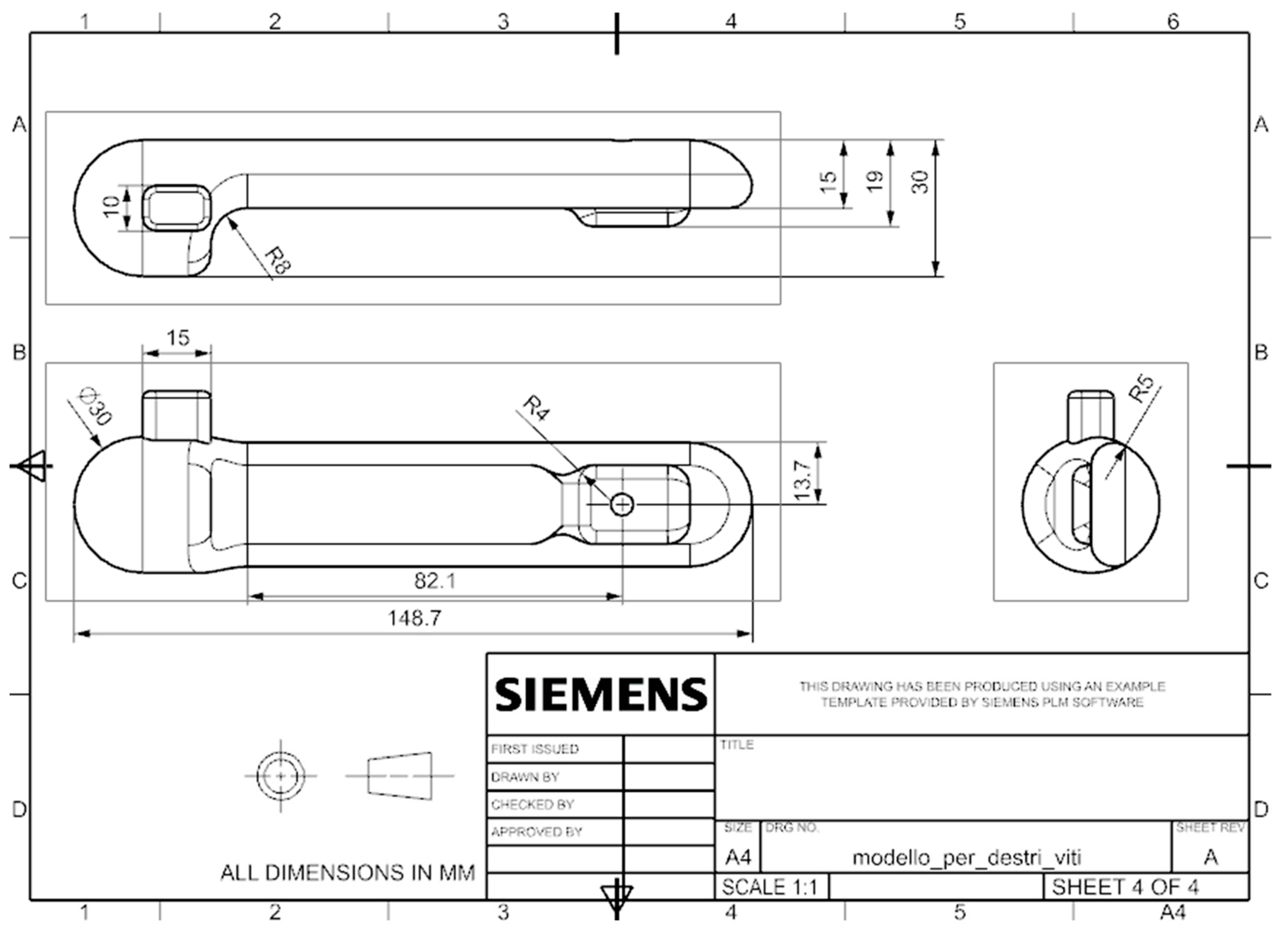
2.1.5. Design Prototype
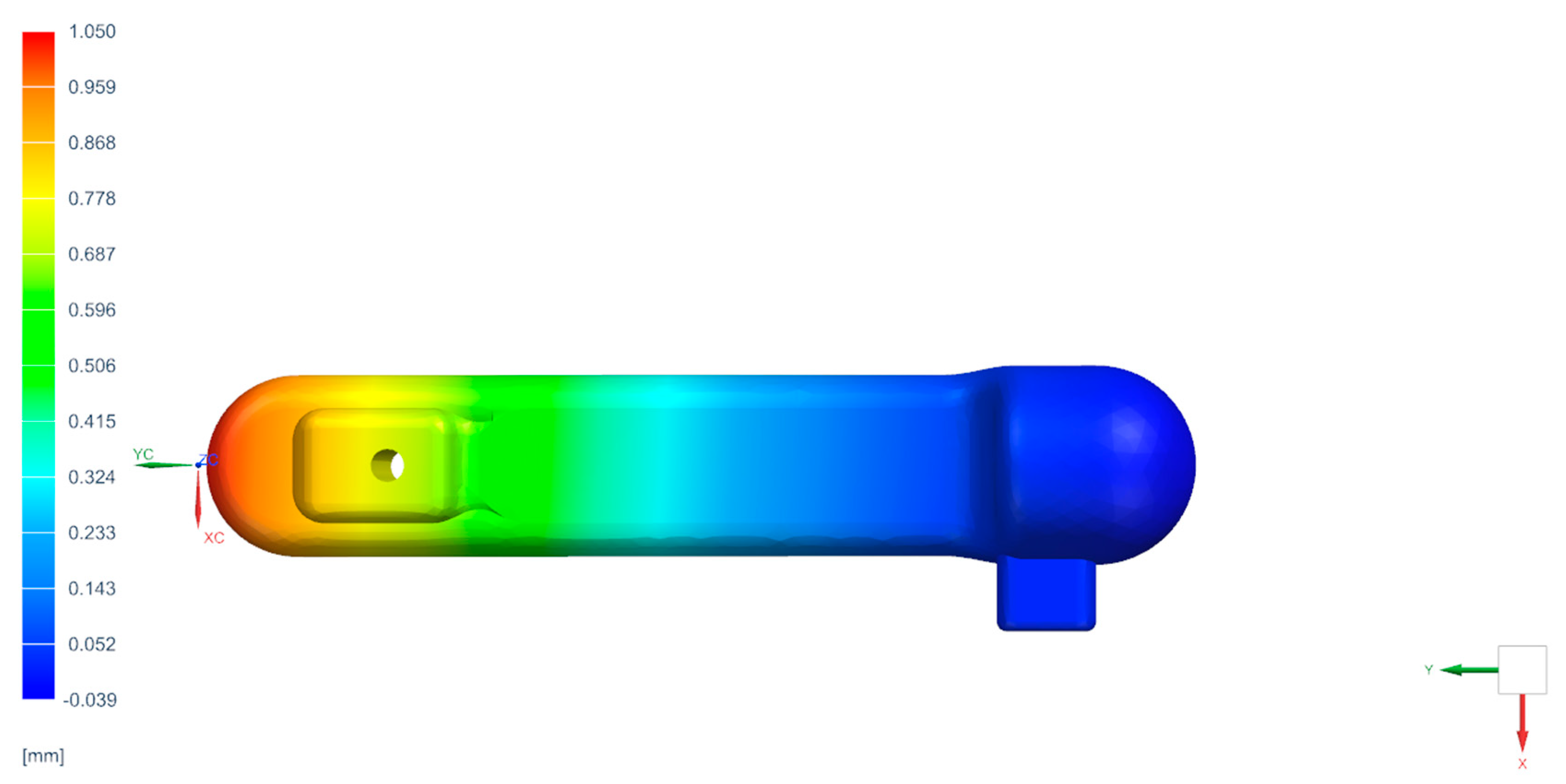
The torque wrench was fabricated using Siemens NX 1851 software. The component was designed to facilitate usage by both left-handed and ambidextrous individuals. For simplicity, Figure 2 illustrates the device configured for ambidextrous use.
The system involves mounting the load cell at one end using a threaded connection, and the force acting on the system is calculated through the deformation of the free end. The device was designed for additive manufacturing using the Fused Deposition Modeling (FDM) technique, with Polylactic Acid (PLA) as the chosen material (Table 1) [18].
The printing parameters employed are detailed in Table 2.

2.1.6. FEM Analysis

To ensure the designed device withstands usage without structural failure, a Finite Element Analysis (FEA) was conducted. The system was discretized using the specifications outlined in Table 3. The dimensions listed in Table 3 correspond to the number of nodes and elements resulting from the sensitivity analysis.
The system was constrained with a fixed boundary condition (depicted in gray in Figure 3) at the locations corresponding to where the wrench for tightening prosthetic screws will be attached. Considering the most critical loading condition on the system, it was subjected to a 20 kg force applied parallel to the axis of the hole where the load cell is mounted (depicted in red in Figure 3).

3. Results and Discussion

Based on the conducted Finite Element Analysis (FEA), it was determined (Figure 4) that the maximum deflection in the z-direction under the worst-case loading scenario is 1 mm. The system is fixed in place, rendering it immobile and preventing rotation along the x-axis. However, during measurements, the system is free to rotate, resulting in lower deformation values.
In addition to assessing the maximum deformation experienced by the system, we evaluated the accuracy of the load cell under varying applied weights. Accuracy was assessed by calculating the Root Mean Square Error (RMSE) and the relative measurement error across a weight range from 0.01 kg to 0.6 kg. These measurements aimed to determine the load cell’s minimum detectable load variation. It can be confidently stated that the load cell is capable of accurately detecting load variations as small as 20 g (Table 4).

4. Conclusions

The study aimed to establish a cost-effective and precise method for single-handedly calculating the implant preload. Additionally, it sought to design a component suitable for both left-handed and ambidextrous individuals, ensuring universality within the system. The analysis results confirmed the viability of using PLA as the material for the component, as even under the most challenging conditions, the maximum calculated deflection remained within 1 mm. Moreover, the load cell utilized for measurements demonstrated its capability to detect a minimum load of 20 g. Future developments will involve conducting experimental tests with users of varying expertise levels to assess the extent to which the applied load varies among users and its potential impact on coupling failure.

Author Contributions

Conceptualization, D.M., L.F. and L.D.; methodology, D.M., L.F. and L.D.; software, D.M., M.S., G.R. and L.D.; validation, D.M., L.F. and L.D.; formal analysis, D.M., L.F. and L.D.; investigation, D.M., L.F., G.R. and L.D.; resources, L.F.; data curation, D.M. and L.D.; writing—original draft preparation, D.M., L.F., M.S., G.R. and L.D.; writing—review and editing, D.M., L.F., G.R. and L.D.; visualization, D.M., L.F. and L.D.; supervision, D.M., L.F., G.R. and L.D.; project administration, D.M. All authors have read and agreed to the published version of the manuscript.

Funding

This paper received no external funding.

Institutional Review Board Statement

Not applicable.

Informed Consent Statement

Not applicable.

Data Availability Statement

The data presented in this study are available on request from the corresponding author.

Conflicts of Interest

The authors declare no conflicts of interest.

References

  1. Wieser, M.; Liu, J.; Hernandez, P.; La Belle, J.T. A Comparison of Force Sensing for Applications in Prosthetic Haptic Feedback. Crit. Rev. Biomed. Eng. 2019, 47, 109–119. [Google Scholar] [CrossRef] [PubMed]
  2. Hendrich, N.; Wasserfall, F.; Zhang, J. 3D Printed Low-Cost Force-Torque Sensors. IEEE Access 2020, 8, 140569–140585. [Google Scholar] [CrossRef]
  3. Rasheedha, A.; Srinathi, K.; Sivalavanya, T.; Monesha, R.R.; Nithin, S. Arduino based Automated Dosage Prescriptor using Load Cell. In Proceedings of the 2020 4th International Conference on Electronics, Communication and Aerospace Technology (ICECA), Coimbatore, India, 5–7 November 2020; pp. 85–89. [Google Scholar] [CrossRef]
  4. Hubbard, B.R.; Pearce, J.M. Open-Source Digitally Replicable Lab-Grade Scales. Instruments 2020, 4, 18. [Google Scholar] [CrossRef]
  5. Kondaveeti, H.K.; Kumaravelu, N.K.; Vanambathina, S.D.; Mathe, S.E.; Vappangi, S. A systematic literature review on prototyping with Arduino: Applications, challenges, advantages, and limitations. Comput. Sci. Rev. 2021, 40, 100364. [Google Scholar] [CrossRef]
  6. Fiorillo, L.; Milone, D.; D’Andrea, D.; Santonocito, D.; Risitano, G.; Cervino, G.; Cicciù, M. Finite Element Analysis of Zirconia Dental Implant. Prosthesis 2022, 4, 490–499. [Google Scholar] [CrossRef]
  7. Milone, D.; Fiorillo, L.; Alberti, F.; Cervino, G.; Filardi, V.; Pistone, A.; Cicciù, M.; Risitano, G. Stress distribution and failure analysis comparison between Zirconia and Titanium dental implants. Procedia Struct. Integr. 2022, 41, 680–691. [Google Scholar] [CrossRef]
  8. Milone, D.; Risitano, G.; Pistone, A.; Crisafulli, D.; Alberti, F. A New Approach for the Tribological and Mechanical Characterization of a Hip Prosthesis Trough a Numerical Model Based on Artificial Intelligence Algorithms and Humanoid Multibody Model. Lubricants 2022, 10, 160. [Google Scholar] [CrossRef]
  9. Milone, D.; Nicita, F.; Cervino, G.; Santonocito, D.; Risitano, G. Finite element analysis of OT bridge fixed prosthesis system. Procedia Struct. Integr. 2021, 33, 734–747. [Google Scholar] [CrossRef]
  10. Cervino, G.; Cicciù, M.; Fedi, S.; Milone, D.; Fiorillo, L. FEM analysis applied to OT bridge abutment with seeger retention system. Eur. J. Dent. 2020, 15, 47–53. [Google Scholar] [CrossRef] [PubMed]
  11. Parnia, F.; Yazdani, J.; Fakour, P.; Mahboub, F.; Pakdel, S.M.V. Comparison of the maximum hand-generated torque by professors and postgraduate dental students for tightening the abutment screws of dental implants. J. Dent. Res. Dent. Clin. Dent. Prospect. 2018, 12, 190. [Google Scholar] [CrossRef] [PubMed]
  12. Kose, O.D.; Karataslı, B.; Demircan, S.; Kose, T.E.; Cene, E.; Aya, S.A.; Erdem, M.A.; Cankaya, A.B. In vitro evaluation of manual torque values applied to implant-abutment complex by different clinicians and abutment screw loosening. BioMed Res. Int. 2017, 2017, 7376261. [Google Scholar] [CrossRef]
  13. Kanawati, A.; Richards, M.W.; Becker, J.J.; Monaco, N.E. Measurement of clinicians’ ability to hand torque dental implant components. J. Oral Implantol. 2009, 35, 185–188. [Google Scholar] [CrossRef] [PubMed]
  14. Goswami, M.M.; Kumar, M.; Vats, A.; Bansal, B.A.S. Evaluation of dental implant insertion torque using a manual ratchet. Med. J. Armed Forces India 2015, 71, S327–S332. [Google Scholar] [CrossRef] [PubMed]
  15. Choi, H.; Hong, M.H. Finite Element Analysis of the Effect of Tightening Torque on the Connection Stability of a Two-Piece Zirconia Implant System. Adv. Mater. Sci. Eng. 2022, 2022, 1456475. [Google Scholar] [CrossRef]
  16. Alnasser, A.H.; Wadhwani, C.P.K.; Alsarraf, E.Y.; Kattadiyil, M.T.; Lozada, J. Effect of implant abutment screw materials and tightening protocols on reverse tightening values: An in vitro study. J. Prosthet. Dent. 2023. [Google Scholar] [CrossRef] [PubMed]
  17. Nourizadeh, A.; Shafiee, E.; Khorramdel, A.; Mousavi, S.A.; Rahbar, M. Comparison of reverse torque values of abutment screws with the application of oil-based and water-based antibacterial agents. J. Dent. Res. Dent. Clin. Dent. Prospect. 2022, 16, 238. [Google Scholar] [CrossRef] [PubMed]
  18. Aloyaydi, B.; Sivasankaran, S.; Mustafa, A. Investigation of infill-patterns on mechanical response of 3D printed poly-lactic-acid. Polym. Test. 2020, 87, 106557. [Google Scholar] [CrossRef]
Figure 1. Image representing wiring for optimal signal IintegrityE+ (green) from the load cell connects to E+ on the HX711 and Arduino GND. E− (orange) is linked to HX711’s E−. A− (brown) connects to HX711’s A−. A+ (purple) joins with HX711’s A+. HX711 VCC is connected to Arduino’s 5V. The TX and RX pins are meticulously connected to Arduino board’s D2 and D3, respectively.
Engproc 56 00252 g001
Figure 2. An orthogonal projection view represents the design of the torque wrench used for the measurements.
Engproc 56 00252 g002
Figure 3. Loads and constraints applied to the system are depicted in the figure. The loads are applied orthogonally to the xy plane, as indicated by the action lines on the left side of the image. The screws are of a fixed type and are applied within the socket of the wrench used to tighten the system.
Engproc 56 00252 g003
Figure 4. Deformation along the z axis of the component calculated in the most severe load condition applied to the system.
Engproc 56 00252 g004
Table 1. Mechanical properties.
Printing Specifications
Density1.24 g/cm3
Young’s modulus3100 MPa
Tensile strength60 MPa
Elongation9%
Table 2. Specifications used to print the component with the FDM technique.
Printing Specifications
Layer Height 0.4 mm
Infill Density100%
Wall Line Count5
Printing Temperature200 °C
Build Plate Temperature60 °C
Print Speed60 mm/s
Table 3. Number of nodes and elements and type of element used during the FEA analysis.
Printing Specifications
Element type Tetra 10-Solid 186
Numbers of elements23,905
Numbers of nodes38,841
Table 4. Accuracy calculation using the Root Mean Square Error (RMSE) and the relative measurement error across a weight range from 0.01 kg to 0.6 kg.
WeightMeanStandard DeviationRMSERel Error
0.01 kg0.0128 kg0.0060 kg0.0028 kg28%
0.02 kg0.0210 kg0.0026 kg0.0010 kg5%
0.05 kg0.0486 kg0.0040 kg0.0014 kg2.8%
0.1 kg0.0977 kg4.9237 × 10−4 kg0.0023 kg2.3%
0.5 kg0.4999 kg6.6299 × 10−4 kg1.0000 × 10−4 kg0.2%
0.6 kg0.6030 kg1.1703 × 10−16 kg0.0030 kg0.5%
Disclaimer/Publisher’s Note: The statements, opinions and data contained in all publications are solely those of the individual author(s) and contributor(s) and not of MDPI and/or the editor(s). MDPI and/or the editor(s) disclaim responsibility for any injury to people or property resulting from any ideas, methods, instructions or products referred to in the content.

