
Modeling Fracture Properties for Heterogeneous Materials Using J-Integral †
by
 , and
, and
Mehdi Boudouh
1,* ,
,
Brahim El Khalil Hachi
1,
Hadi Taibi
1,
Mohamed Haboussi
2,
María Fernández Raga
3 and
Dahmane Hachi
1 1
Laboratory of Development in Mechanical and Materials (LDMM), Ziane Achour University, Djelfa 17000, Algeria
2
Laboratory of Process and Materials Sciences (LSPM), Sorbonne Paris Nord University, UPR 3407 CNRS, F-93430 Villetaneuse, France
3
Department of Applied Physics, University of León, 24007 León, Spain
*
Author to whom correspondence should be addressed.
†
Presented at the 4th International Electronic Conference on Applied Sciences, 27 October–10 November 2023; Available online: https://asec2023.sciforum.net/ .
Eng. Proc. 2023, 56(1), 277; https://doi.org/10.3390/ASEC2023-15814
Published: 2 November 2023
(This article belongs to the Proceedings of The 4th International Electronic Conference on Applied Sciences)
Abstract
:The majority of classical methods which analyze the stability of existing cracks are based on theorems which calculate the forces in a state of limit equilibrium and do not take into consideration the deformation of the structure and the internal constraints thereof. This is not entirely consistent with what exactly happens in reality. For this purpose, we have proposed this study which analyzes the stability of cracks by the stress intensity factor through the calculation of the J-Integral, which is used in the calculation of the stress intensity factor. The stress intensity factor is a mechanical parameter, its values play a very important role in predicting the cracked state of the structure, and when it takes a certain value which is equal to the toughness of the material, the crack will cause the rupture of the structure. There are several methods for calculating the stress intensity factor. We have chosen to calculate it using the energy method because the direct calculation of the latter poses a problem because of the secularity of the flow around the crack. In this paper, we used the J-Integral and the energy release time to calculate the stress intensity factor. We also calculated using the laws of country the growth rate and the necessary number of cycles for the propagation of a crack.
1. Introduction
All structures contain cracks. These vary depending on the nature of their presence, as they may appear as a material or form defect during the construction of the material. These cracks are considered to be the main contributor to various failures in structures subjected to loads which can be static, cyclic or dynamic.
Fracture mechanics is an area which is interested in the study and prediction of the initiation and propagation of cracks in materials and structures.
The main dates which mark the development of fracture mechanics are 1920, when Griffith [1] showed that the rupture of an elastic-brittle medium can be characterized by a global variable, which will later be called the restitution rate of energy, and 1957, when, from the study of the singularities of the stress field, Irwin introduced the notion of stress intensity factor (SIF) [2].
The 1960s–1980s saw the rise and then maturity of fracture mechanics, especially digital developments and the treatment of non-linear problems. Many works were published during this period.
In 1968, Rice [3] introduced the notion of integrals whose properties made it possible to characterize the toughness of a material when the plasticity is no longer confined to the crack tip.
Brittle fracture mechanics is very widely used by engineers and mechanics because it uses global energy theorems such as the stress intensity factor (SIF) [4].
To value the risk of the structure, it is necessary to access the numerical outputs of simulations.
The finite element method has made it possible to study fracture mechanics from a numerical point of view, thus offering precise and detailed solutions to more complex problems [5]. In our study, we will use the COMSOL® software version 5.6 to calculate the stress intensity factor (SIF). The numerical calculation is based on the contour J-Integral.
The stress and strain field at the crack tip include (1/√r) type singularities [6]. In order to capture this singularity, the numerical model must include so-called ‘singular’ elements.
2. Materials and Method
The J-Integral (curvilinear integral) is a method of calculating the rate of strain relaxation or work energy (energy) per unit area fractured in a material.
The J-Integral is calculated by the following relation:
where W is the strain energy density:
And T is the traction vector defined as:
The J-Integral has the following relationship with the SIF in mode I:
where E is the modulus of elasticity.
2.1. Energy Release Rate
We can calculate the J-Integral without using path integration because there is an equality between the value of the J-Integral and the rate of energy restitution G. This is true in the case of an elastic material.
The potential energy of an elastic body is:
: 1st-term strain energy.
: boundary surface effort tractive.
Therefore, one can use only one of these two terms to calculate the potential energy.
The total strain energy density is a variable which facilitates the calculation of the rate of energy restitution G.
2.2. Propagation of a Crack
When subjected to periodic loading, the rate of crack growth (in meters per load cycle) can be expressed by the Paris law:
η and n are material properties and ΔKI is the variation of SIF.
3. Results and Discussion
Problem of Cracked Square Structure Problem Contains Two Tensile Inclusions
The structure is a square plate containing a single horizontal edge crack in the middle of the left vertical edge, subjected to a single tensile test shown in (Figure 1) and a single horizontal edge crack in the middle of the left vertical edge. The length of the crack varies from a = 0.5 m to a = 0.7 m, and the plate is subjected to stress loading σ = t as shown in Figure 1, and the lower horizontal edge in the y direction, with t presenting the loading parameter.
The load varies from 0 to 20 MPa, and we take ΔKI to be equal to the calculated KI. Note that the value of the coefficient A depends on the unit of the stress intensity factor in a rather complex way because of the power m, which in general is non-integer.
There are three ways to calculate the J-Integral:
- A circle around the tip of the crack with a radius corresponding to half the length of the crack.
- A circle around the tip of the crack with a radius equal to 0.7 times the length of the crack.
- The outer limits, excluding the surface of the crack.
The mesh is made up of triangular elements, and the maximum element size he = 0.01.
The analytical solution for the stress intensity factor is:
where f is a correction factor.
The expression in Equation (11) assumes that the plate is long, so the height is significantly greater than the width. The stress field in Figure 2 indicates that this assumption is satisfied.
Two simulations are made for this problem, and for each simulation, the mechanical properties of the inclusion structure have different properties.
Simulation (a): The mechanical properties of the structure are the Young’s modulus E = 69 × 109 Pa, the Poisson’s ratio ν = 0.33, and the density ρ = 2730 kg/m3 with a loading ρ between 0 and 20 MPa.
Material properties of inclusions are Young’s modulus E = 2.06 × 10¹¹ Pa, Poisson’s ratio ν = 0.3, and density ρ = 7850 kg/m3.
Simulation (b): The material properties of the structure are the Young’s modulus E = 2.06 × 10¹¹ Pa, the Poisson’s ratio ν = 0.3, and the density ρ = 7850 kg/m3 with a loading ρ between 0 and 20 MPa.
The mechanical properties of the inclusions are the Young’s modulus E= 69× 109 Pa, the Poisson’s ratio ν = 0.33, and the density ρ = 2730 kg/m3.
The results obtained in Figure 2 show the deformation of each structure and the von Mises stress concentrations.
We notice in Figure 2a the distribution of stresses in the two structures (a) and (b), This distribution starts from the places where the loading is applied and gradually propagates throughout the structure.
For Figure 2a, the structure is made of aluminum and the inclusions are made of steel. We notice that the stresses are distributed throughout the structure except the inclusions which remain healthy. This is due to their greater rigidity than the structure, because we notice a concentration of stress around the inclusions without entering inside, which explains the deformation of the structure and the inclusions remaining healthy.
For Figure 2b, we have the opposite: the structure is made of steel and the inclusions are made of aluminum. We note the distribution of stresses throughout the structure, including the inclusions in which the concentration of stresses was greater than that of the structure, which explains why they were subjected to greater deformation than the structure.
In both structures, there is a singularity of stress at the front of the crack which explains why the crack propagates.
Figure 3 shows the calculation of the SIF for the three lines, tabulated in the Cracks (solids) evaluation group, which shows excellent agreement with the reference value. The largest deviation for any of the crack lengths and integration paths investigated is less than 0.3%.
4. Conclusions
In this work, a numerical implementation was made to calculate the mode I stress intensity factor using the J-Integral method for two−dimensional structures.
First, we presented a theoretical aspect on the main physical quantities and parameters used in this study, the FIC and the J-Integral. the numerical implementation of the latter fact using the finite element method (FEM), Several numerical problems have dealt with this method.
We concluded that in both modes, the profile of the energy restitution rates is not constant in the width of the specimen.
Moreover, we showed that the method of the J-Integral is a rather good approximation of the results provided by the finite element method by comparing with the other numerical methods (strain energy, loads energies) and also the analytical solution.
The strong point of this method is that it takes into account the asymmetry of the specimen and the multi-material aspect.
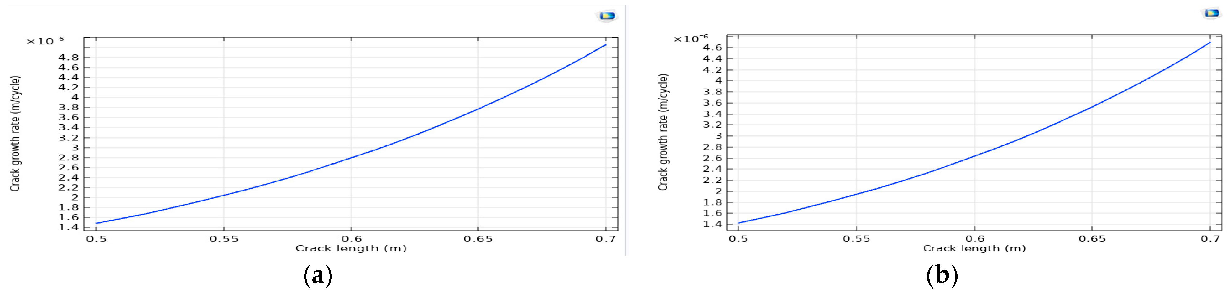
Finally, it is interesting to note that the shape of the curve (energy release time G as a function of the crack length a) will not have a parabolic shape (as in Figure 4) because the force at rupture varies according to a.
Author Contributions
Conceptualization, M.B.; Software, M.B. and B.E.K.H.; Validation, M.B. and D.H. and M.H.; Formal analysis, M.B. and H.T.; Resources, M.B. and B.E.K.H.; Data curation, M.B. and M.F.R.; Writing—original draft, M.B.; Writing—review and editing, M.B. and B.E.K.H. and D.H.; Supervision, M.B. and B.E.K.H.; Project administration, M.B., B.E.K.H., M.F.R. and M.H.; Funding acquisition, M.B., B.E.K.H., M.F.R. and M.H. All authors have read and agreed to the published version of the manuscript.
Funding
This project was financially supported by the Directorate General for Scientific Research and Technological Development of the Algerian Ministry of Higher Education and Scientific Research in Algeria, the Laboratory of development in mechanic and materials (LDMM) of Djelfa University, Algeria, and the Laboratory of Process and Materials Sciences (LSPM), University of Sorbonne Paris Nord, France.
Institutional Review Board Statement
Not applicable.
Informed Consent Statement
Not applicable.
Data Availability Statement
The simulation was carried out in the calculation station.
Conflicts of Interest
The authors declare no conflicts of interest.
References
- Griffith, A.A. The phenomena of rupture and flow in solids. Philos. Trans. R. Soc. Lond. 1920, 221, 163–198. [Google Scholar]
- Irwin, G.R. Analysis of stresses and strains near the end of a crack traversing a plate. J. Appl. Mech. 1957, 24, 361–364. [Google Scholar] [CrossRef]
- Rice, J.R. A Path Independent Integral and the Approximate Analysis of Strain Concentration by Notches and Cracks. J. Appl. Mech. 1968, 35, 379–386. [Google Scholar] [CrossRef]
- Elguedj, T. Simulation Numérique de la Propagation de Fissure en Fatigue par la Méthode des Éléments Finis Étendus: Prise en Compte de la Plasticité et du Contact-Frottement. Ph.D. Thesis, INSA de Lyon, Villeurbanne, France, 2006. [Google Scholar]
- Pierre-Olivier, B. Contribution to Numerical Modeling in Fracture Mechanics and Multi-Material Structures. Ph.D. Thesis, Ecole Nationale Superieur des mines de Paris, Paris, France, 2000. [Google Scholar]
- Alan, T.; Zehnder, P. Reading Notes on Fracture Mechanics; Department of Theoretical and Applied Mechanics, Cornell University: Ithaca, NY, USA, 2009. [Google Scholar]
Figure 1.
Cracked square plate with two inclusions. (a): steel structure reinforced by two aluminum inclusions, (b): aluminum structure reinforced by two steel inclusions.
Figure 1.
Cracked square plate with two inclusions. (a): steel structure reinforced by two aluminum inclusions, (b): aluminum structure reinforced by two steel inclusions.

Figure 2.
The von Mises stresses. (a): steel structure reinforced by two aluminum inclusions, (b): aluminum structure reinforced by two steel inclusions.
Figure 2.
The von Mises stresses. (a): steel structure reinforced by two aluminum inclusions, (b): aluminum structure reinforced by two steel inclusions.
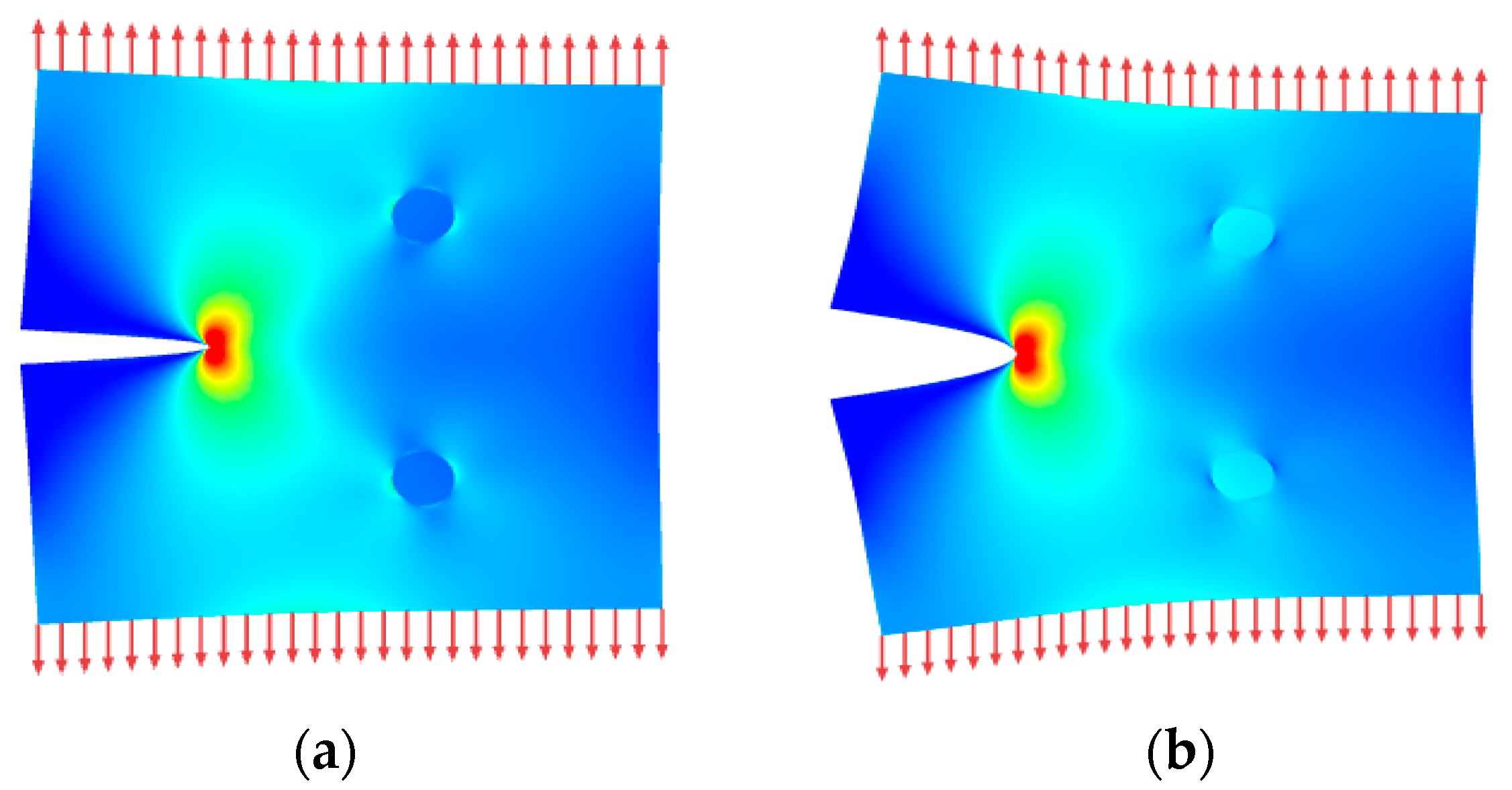
Figure 3.
Energy release rates and J-Integral as a function of crack length. (a): steel structure reinforced by two aluminum inclusions, (b): aluminum structure reinforced by two steel inclusions.
Figure 3.
Energy release rates and J-Integral as a function of crack length. (a): steel structure reinforced by two aluminum inclusions, (b): aluminum structure reinforced by two steel inclusions.
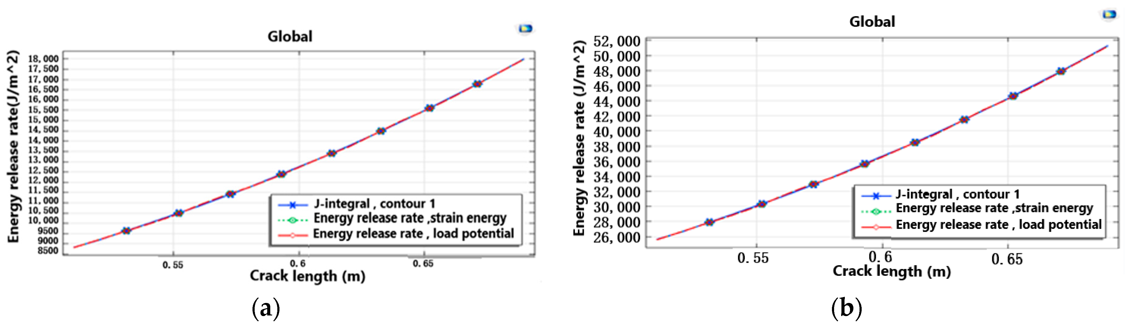
Figure 4.
Crack growth rate as a function of crack length. (a): steel structure reinforced by two aluminum inclusions, (b): aluminum structure reinforced by two steel inclusions.
Figure 4.
Crack growth rate as a function of crack length. (a): steel structure reinforced by two aluminum inclusions, (b): aluminum structure reinforced by two steel inclusions.
Disclaimer/Publisher’s Note: The statements, opinions and data contained in all publications are solely those of the individual author(s) and contributor(s) and not of MDPI and/or the editor(s). MDPI and/or the editor(s) disclaim responsibility for any injury to people or property resulting from any ideas, methods, instructions or products referred to in the content. |
© 2023 by the authors. Licensee MDPI, Basel, Switzerland. This article is an open access article distributed under the terms and conditions of the Creative Commons Attribution (CC BY) license (https://creativecommons.org/licenses/by/4.0/).
Share and Cite
MDPI and ACS Style
Boudouh, M.; Hachi, B.E.K.; Taibi, H.; Haboussi, M.; Raga, M.F.; Hachi, D. Modeling Fracture Properties for Heterogeneous Materials Using J-Integral. Eng. Proc. 2023, 56, 277. https://doi.org/10.3390/ASEC2023-15814
AMA Style
Boudouh M, Hachi BEK, Taibi H, Haboussi M, Raga MF, Hachi D. Modeling Fracture Properties for Heterogeneous Materials Using J-Integral. Engineering Proceedings. 2023; 56(1):277. https://doi.org/10.3390/ASEC2023-15814
Chicago/Turabian StyleBoudouh, Mehdi, Brahim El Khalil Hachi, Hadi Taibi, Mohamed Haboussi, María Fernández Raga, and Dahmane Hachi. 2023. "Modeling Fracture Properties for Heterogeneous Materials Using J-Integral" Engineering Proceedings 56, no. 1: 277. https://doi.org/10.3390/ASEC2023-15814