
Structural Analysis of Molds with Conformal Cooling Channels: A Numerical Study †
by
 ,
,
Hugo Miguel Silva
1,2,* ,
,
João Tiago Noversa
1,
Hugo Luís Rodrigues
1,
Leandro Fernandes
1 and
António José Pontes
1 1
IPC—Institute for Polymers and Composites, University of Minho, Campus de Azurém, 4800-058 Guimaraes, Portugal
2
proMetheus, Instituto Politécnico de Viana do Castelo, Rua Escola Industrial e Comercial Nun’Álvares, 34, 4900-347 Viana do Castelo, Portugal
*
Author to whom correspondence should be addressed.
†
Presented at the 4th International Electronic Conference on Applied Sciences, 27 October–10 November 2023; Available online: https://asec2023.sciforum.net/ .
Eng. Proc. 2023, 56(1), 295; https://doi.org/10.3390/ASEC2023-16614
Published: 8 December 2023
(This article belongs to the Proceedings of The 4th International Electronic Conference on Applied Sciences)
Abstract
:This article presents noteworthy discoveries pertaining to molds, featuring innovative conformal cooling channel designs. The aim of this study is to determine the upper limit of pressure that the components can endure in a real-world injection molding scenario. The resistance and stiffness properties of the examined geometries are assessed using linear structural analyses conducted in the ANSYS Workbench finite element method software version 2020 R2. Multiple metrics are employed to analyze the outcomes. Upon thorough examination and analysis of the obtained results, it was determined that specific configurations exhibit a high degree of compatibility with the prevailing operational parameters inherent to the injection molding procedure.
1. Introduction
Extensive research has been undertaken regarding the design and modeling of conformal cooling channels (CCCs) in the context of injection molds. Various simulation technologies are used to analyze mold and channel designs. Dimla et al. (2005) employed I-DEASTM moldflow analysis to ascertain the most favorable channel position [1]. In their study, Saifullah and Masood (2007) conducted an investigation on the concept of “part cooling time” by using the thermal analysis program ANSYS [2]. In a study conducted by Saifullah et al. (2009), it was observed that when assessing conventional and quadratic CCC profiles through the use of MPI simulation software, conformal channels exhibited a cooling rate that was 38% faster compared to conventional channels [3]. In their study, Gloinn et al. (2007) employed a finite element method (FEM) analysis to ascertain the mold temperature. The analysis focused on the with the utilization of an ABS polymer as the molten material and the intake of chilling water [4]. In 2007, a study conducted by the authors of [5] examined the thermal impacts of cooling channel design in injection molding using Moldflow Plastic Insight 3.1. The authors presented a novel criterion for CC construction. In order to illustrate the advantages of a cooling loop, Wang et al. [6] employed identical modeling techniques to simulate the temperature of a singular segment. In 2017, Khan et al. conducted a comparative analysis of the cooling time, total cycle time, volumetric shrinkage, and temperature change associated with serial, parallel, and additive parallel cooling channels [7]. Mayer (2010) succinctly establishes a correlation between four key design criteria for additive manufacturing. Previous studies have indicated that the utilization of noncircular channel cross-sections has the potential to enhance cooling efficiency [8]. The investigation of cooling tubes with varying spacing for mold tooling has been conducted by researchers [9]. The initial construction of the model involved the use of linear channels. However, a subsequent redesign was implemented, replacing the linear channels with CCCs. This redesign was carried out by employing a meticulous conformal channel design method. The researchers investigated the spatial relationship between the wall and duct, the spacing between pitches, and the diameter of the duct. Only two published articles that present novel research on the topic of the structural modeling of molds, including conformal cooling channels, were found [10,11]. The primary objective of performing structural analysis in the context of these two injection molding experiments was to validate the geometric aspects relevant to structural design. A comprehensive investigation comparing the stiffness, resistivity, and other pertinent attributes of different injection mold geometries has not been conducted. As evidenced, the literature on numerical simulation holds significant importance. The assessment of the structural integrity of molds incorporating internal reinforcement and a cellular structure was not conducted. This study proposes various cooling channel layouts for injection molds that possess internal cavities. The efficacy of specific forms was assessed using a structural static analysis conducted under typical loading conditions encountered in injection molding. The present study assessed the safety geometry of injection molds. The outcomes of this study can be employed to assess and evaluate the tolerance levels of different geometries under injection molding pressures.
2. Procedure
2.1. Material Properties
The material used in the simulations was steel P20. It is assumed that the material behaves as orthotropic. The properties of the steel used are shown in Table 1.
The values of Gxy, Gyz, and Gxz are required in ANSYS Workbench 2020 R2 for the selected material model.
2.2. Numerical Models
In Figure 1, the CAD files (geometries) of the studied models are displayed.
2.3. Conditions
In order to replicate the pressure exerted on the injected part during the injection molding process, a distributed load (pressure) was applied to the upper surfaces of the component, including the cooling channels, as shown in Figure 2. The pressure exerted was measured to be 100 megapascals (MPa). In the context of an injection molding machine mold, the object was securely immobilized to closely simulate real-world conditions. Figure 2 illustrates the loads and boundary conditions imposed on numerical models.
The mesh type is tetrangular, free with a mean element size of 1.25 mm. The analyzed geometries were built in the computer-aided design (CAD) software Solidworks 2020. The geometries were exported in a neutral file format and imported into ANSYS Workbench.
3. Results and Discussion
In order to evaluate the distribution of stresses and displacements, contours were created in ANSYS Workbench. In this situation, the goal of mechanical design and computer-aided engineering (CAE) engineers should be to lower critical stresses by reinforcing the part with the highest stresses and/or displacements. Alternatively, by reducing material on the points of the lowest stresses, topology optimization principles can be used automatically (via software) or manually. Regarding the current study, the shapes could aid in the redesign of the components to achieve the least amount of displacement and stress. The Huber–Mises criterion equivalent stresses for the Bulk model are graphically displayed in Figure 3. Figure 3b is a larger version of Figure 3a.
The Huber–Mises stresses are the highest around the center of the load application zones, as depicted by the contours in Figure 3. It is crucial to remember that this is an equivalent stress, which is determined using the major stresses, even though the contour may not show distinct gradients of results. The correlations among the primary stresses may give rise to outcomes with non-trivial contours, like the one in question. The Bulk model’s graphical findings are displayed in Figure 4. In terms of displacement along the y axis, refer to Figure 3a and Figure 4a for the coordinate system. The results are displayed in Figure 4a. Figure 4b is a larger version of Figure 4a. As would be predicted, the contour of Figure 4 displays substantial vertical deflections where the load is applied. The distance to the locations of load application results in a deflection gradient.
The von Mises strength is illustrated in Figure 5. Figure 6 illustrates the representation of commonly used high-strength steels, exhibiting yield strengths of 300, 500, 700, and 900 MPa.
From Figure 6, it is shown that steel selection is an important design factor to consider, as steels with a higher yield strength allow us to obtain structural integrity, even in molds that are not high performers. Notably, the vertical axis of the graph is presented on a distinct scale, while the horizontal lines are emphasized with boldness.
According to the findings presented in Figure 5 and Figure 6, it can be inferred that the existing configurations of the New1 and New2 geometries are deemed impracticable due to the inability of any steel material to endure the excessive stress levels associated with them. The Bulk, New2, New4, and New5 satisfy the specified criteria for structural yield strength, which is set at 700 MPa. The structural analysis reveals that the Bulk, New2, and New4 geometries exhibit a satisfactory performance, as they can withstand a stress level of 500 MPa. At a yield strength of 300 MPa, only the Bulk and the geometry New2 demonstrate a maximum von Mises strength below the yield point. Figure 7 illustrates the maximum displacements in the y direction for each respective shape.
The stiffness results of Figure 7 suggest that the upper surface undergoes the most deflections due to the distributed load applied to it and the larger distance to the restricted areas. The impact of these two parameters on the gradient of the deflections depicted in Figure 7 is significant.
Based on the analysis conducted, it can be inferred that the geometries New2, New4, and New5 exhibit a plausible potential for viable implementation within operational environments and for the specific materials under consideration. While it is acknowledged that design alterations are required, it is worth considering the potential intrigue of the New1, New3, and New6 geometries. Upon comparing the outcomes depicted in Figure 5 and Figure 6, it becomes evident that disparities exist between strength (Figure 5) and stiffness (Figure 6). The reason for this discrepancy lies in the fact that the von Mises yield criterion incorporates primary stresses, but the deflections under consideration only consider a single direction.
4. Conclusions
The following conclusions can be inferred from this work:
- If the ANSYS APDL input files are appropriately configured, the procedure can be implemented on molds of any dimensions and with any number of cooling channels.
- This study aimed to examine the structural behavior of molds that incorporate conformal cooling channels. Extensive research has been dedicated to the investigation of conformal cooling channels in recent years, yet limited knowledge exists regarding their structural behavior.
- In the process of injection molding, it is common for the mold to experience pressures reaching magnitudes of several hundred MPa. The use of conformal cooling channels in injection molds under operational settings necessitates the use of static analysis as a crucial design tool for simulating structural behavior.
- The advancement of additive printing technology will facilitate the development and experimentation of conformal cooling conduits. This approach enables the use of different mold diameters, cooling channel counts, and part temperatures.
Author Contributions
Conceptualization, H.M.S.; methodology, H.M.S.; software, H.M.S.; validation, H.M.S.; formal analysis, H.M.S.; investigation, H.M.S.; resources, H.M.S.; data curation, H.M.S.; writing—original draft preparation, H.M.S.; writing—review and editing, L.F., J.T.N. and H.L.R.; visualization, H.M.S.; supervision, A.J.P.; project administration, A.J.P.; funding acquisition, A.J.P. All authors have read and agreed to the published version of the manuscript.
Funding
This research was supported by the Research grant number POCI-01-0247-FEDER-024516, co-funded by the European Regional Development Fund, by the Operational Program “Competitiveness and Internationalization”, in the scope of “Portugal 2020”. H. M. Silva gratefully acknowledge the support provided by the Foundation for Science and Technology (FCT) of Portugal, within the scope of the project of the Research Unit on Materials, Energy and Environment for Sustainability (proMetheus), Ref. UID/05975/2020, financed by national funds through the FCT/MCTES.
Institutional Review Board Statement
Not applicable.
Informed Consent Statement
Not applicable.
Data Availability Statement
The datasets generated during and/or analyzed during the current study are available from the corresponding author on reasonable request.
Conflicts of Interest
The authors declare no conflicts of interest.
References
- Dimla, D.; Camilotto, M.; Miani, F. Design and optimization of conformal cooling channels in injection molding tools. J. Mater. Process. Technol. 2005, 164, 1294–1300. [Google Scholar] [CrossRef]
- Saifullah, A.; Masood, S. Finite element thermal analysis of conformal cooling channels in injection molding. In Proceedings of the 5th Australasian Congress on Applied Mechanics, Brisbane, Australia, 10–12 December 2007. [Google Scholar]
- Saifullah, A.; Masood, S.; Sbarski, I. New cooling channel design for injection molding. In Proceedings of the World Congress on Engineering, London, UK, 1–3 July 2009. [Google Scholar]
- Gloinn, T.O.; Hayes, C.; Hanniffy, P.; Vaugh, K. FEA simulation of conformal cooling within injection molds. Int. J. Manuf. Res. 2007, 2, 162–170. [Google Scholar] [CrossRef]
- Au, K.; Yu, K. A scaffolding architecture for conformal cooling design in rapid plastic injection molding. Int. J. Adv. Manuf. Technol. 2007, 34, 496–515. [Google Scholar]
- Wang, Y.; Yu, K.M.; Wang, C.; Zhang, Y. Automatic design of conformal cooling circuits for rapid tooling. Comput.-Aided Des. 2011, 43, 1001–1010. [Google Scholar] [CrossRef]
- Khan, M.; Afaq, S.K.; Khan, N.U.; Ahmad, S. Cycle Time Reduction in Injection Molding Process by Selection of Robust Cooling Channel Design. Int. Sch. Res. Not. 2014, 2014, 968484. [Google Scholar] [CrossRef]
- Mayer, S. Optimised Mold Temperature Control Procedure Using DMLS; EOS Whitepaper; EOS, GmbH Ltd.: Krailling/Munich, Germany, 2005; pp. 1–10. [Google Scholar]
- Au, K.M.; Yu, K.M. Variable distance adjustment for conformal cooling channel design in rapid tool. J. Manuf. Sci. Eng. 2014, 136, 044501. [Google Scholar] [CrossRef]
- Tan, C.; Wang, D.; Ma, W.; Chen, Y.; Chen, S.; Yang, Y.; Zhou, K. Design and additive manufacturing of novel conformal cooling molds. Mater. Des. 2020, 196, 109147. [Google Scholar] [CrossRef]
- Shen, S.; Kanbur, B.; Zhou, Y.; Duan, F. Thermal and mechanical analysis for conformal cooling channel in plastic injection molding. Mater. Today Proc. 2020, 28 Pt 2, 396–401. [Google Scholar] [CrossRef]
Figure 1.
CAD geometries used in this work, previously built in the CAD software Solidworks 2020.


Figure 2.
Loads applied to the FEM model (left) and degrees of freedom (DOF) constraints applied to all the FEM models (mid and right).
Figure 2.
Loads applied to the FEM model (left) and degrees of freedom (DOF) constraints applied to all the FEM models (mid and right).

Figure 3.
Contours of strength results (a), (b) is a larger version of (a).

Figure 4.
Contours of stiffness results (a), (b) is a larger version of (a).
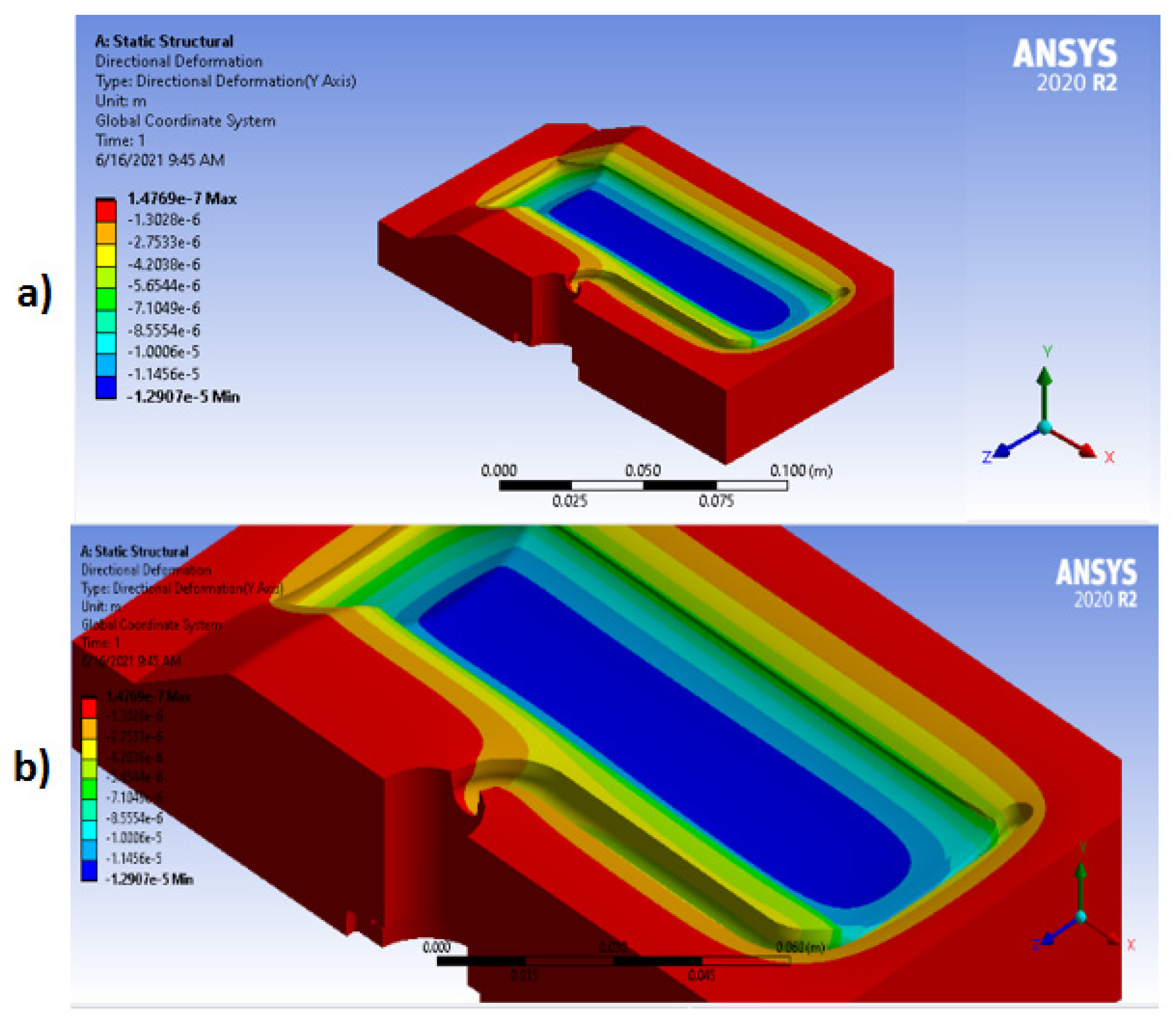
Figure 5.
Von Mises strength for all the studied geometries.
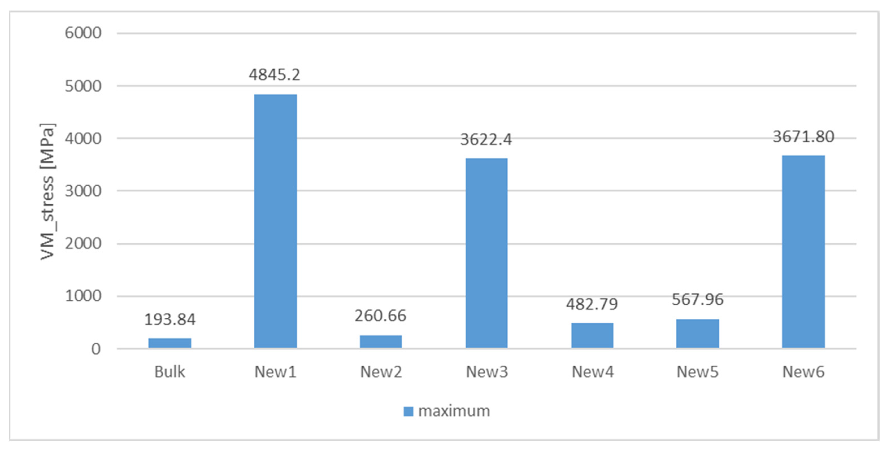
Figure 6.
Representation in a scale compatible with the yield strength of commonly used high-strength steels.
Figure 6.
Representation in a scale compatible with the yield strength of commonly used high-strength steels.
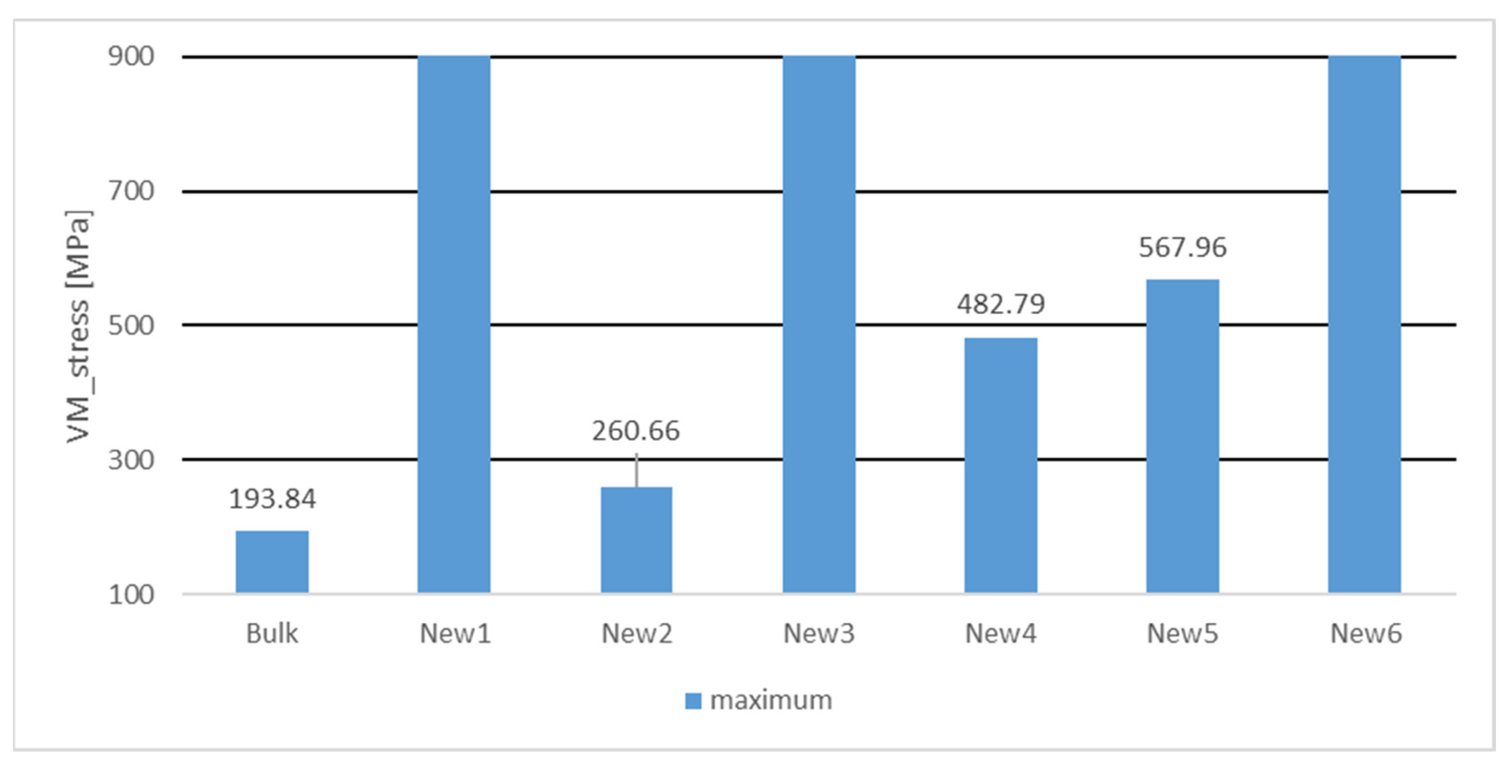
Figure 7.
Y (vertical) displacement for all the studied geometries.
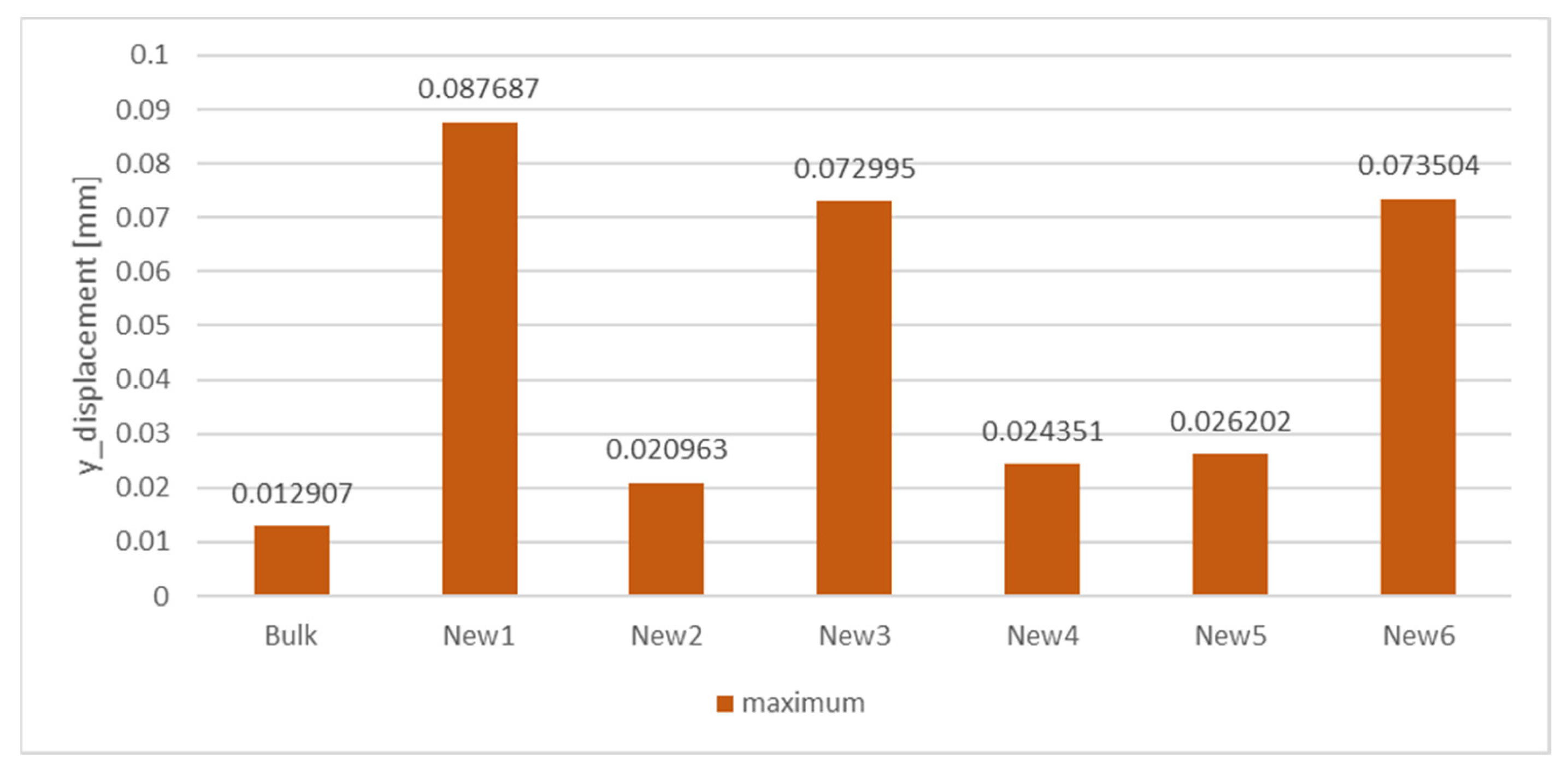
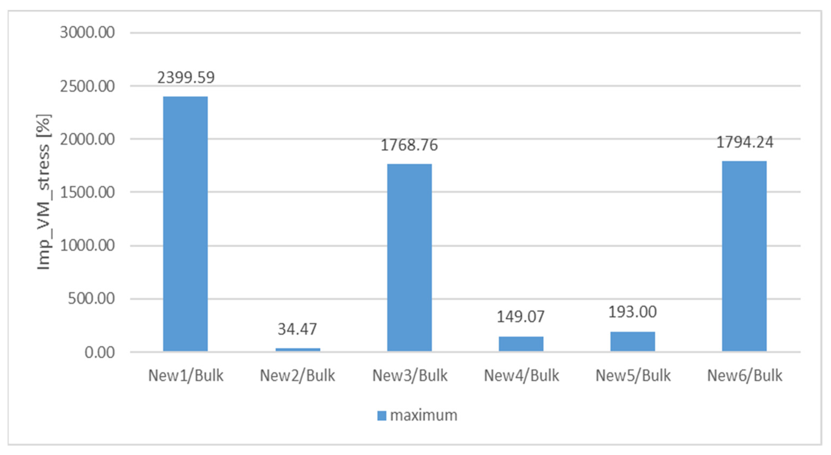
Figure 8.
Improvement results in terms of strength.

Table 1.
Material properties.
| Property | Value | Units |
|---|---|---|
| Ey | 180 | GPa |
| Ex = Ez | 185 | GPa |
| nx = ny = nz | 0.29 | [-] |
| Gxz | 69.8 | GPa |
| Gyz | 71.7 | GPa |
| Gxy | 71.7 | GPa |
| r | 7900 | kg/m3 |
Disclaimer/Publisher’s Note: The statements, opinions and data contained in all publications are solely those of the individual author(s) and contributor(s) and not of MDPI and/or the editor(s). MDPI and/or the editor(s) disclaim responsibility for any injury to people or property resulting from any ideas, methods, instructions or products referred to in the content. |
© 2023 by the authors. Licensee MDPI, Basel, Switzerland. This article is an open access article distributed under the terms and conditions of the Creative Commons Attribution (CC BY) license (https://creativecommons.org/licenses/by/4.0/).
Share and Cite
MDPI and ACS Style
Silva, H.M.; Noversa, J.T.; Rodrigues, H.L.; Fernandes, L.; Pontes, A.J. Structural Analysis of Molds with Conformal Cooling Channels: A Numerical Study. Eng. Proc. 2023, 56, 295. https://doi.org/10.3390/ASEC2023-16614
AMA Style
Silva HM, Noversa JT, Rodrigues HL, Fernandes L, Pontes AJ. Structural Analysis of Molds with Conformal Cooling Channels: A Numerical Study. Engineering Proceedings. 2023; 56(1):295. https://doi.org/10.3390/ASEC2023-16614
Chicago/Turabian StyleSilva, Hugo Miguel, João Tiago Noversa, Hugo Luís Rodrigues, Leandro Fernandes, and António José Pontes. 2023. "Structural Analysis of Molds with Conformal Cooling Channels: A Numerical Study" Engineering Proceedings 56, no. 1: 295. https://doi.org/10.3390/ASEC2023-16614