Proceeding Paper

Enhancing Indoor Position Estimation Accuracy: Integration of Accelerometer, Raw Distance Data, and Extended Kalman Filter in Comparison to Vicon Motion Capture Data †

by
Tolga Bodrumlu
1,* and
Fikret Çalışkan
2
1
Mechatronics Engineering Department, Istanbul Technical University, Istanbul 34025, Turkey
2
Control and Automation Engineering Department, Istanbul Technical University, Istanbul 34025, Turkey
*
Author to whom correspondence should be addressed.
Presented at the 10th International Electronic Conference on Sensors and Applications (ECSA-10), 15–30 November 2023; Available online: https://ecsa-10.sciforum.net/.
Eng. Proc. 2023, 58(1), 40; https://doi.org/10.3390/ecsa-10-16089
Published: 15 November 2023

Abstract

:
Indoor positioning systems are a significant area of research and development, helping people navigate within buildings where GPS signals are unavailable. These systems have diverse applications, including aiding navigation in places like shopping malls, airports, and hospitals and improving emergency evacuation processes. The purpose of this study is to evaluate various technologies and algorithms used in indoor positioning. This study focuses on using raw distance data and Kalman filters to enhance indoor position accuracy. It employs a trilateration algorithm based on Recursive Least Squares (RLS) for initial position estimation and combines the results with accelerometer data. The designed algorithm using real sensor data collected in an ROS(Robot Operating System) environment was tested, and the results obtained were compared with data obtained from the Vicon Indoor Positioning System. In this comparison, the Root Mean Square Error metric was used. As a result of the comparison, it was observed that the error obtained from the designed algorithm is less than that of the Vicon system.

1. Introduction

In recent years, Unmanned Aerial Vehicles (UAVs) have found extensive applications in various fields, including military, industry, agriculture, and tasks like aerial photography and reconnaissance [1,2,3]. However, it is worth noting that these applications are primarily designed for the outdoors and rely on robust GPS signals for accurate positioning. In cases where GPS signals are unavailable or weak, the precision of UAV positioning is significantly impacted. Presently, there is a growing need for indoor UAV technology, particularly for inspection purposes, and this area is closely tied to control optimization and precise path tracking.
Ultra-Wideband (UWB) technology has garnered significant attention due to its high precision in indoor positioning. UWB systems leverage short-duration pulses of radio waves spread across a wide spectrum, enabling accurate distance measurements using time-of-flight and trilateration techniques. Aiello and Shalom [4] delved into the principles of UWB and its significance in achieving precise and real-time positioning. Heimovirta, Salantera, and Röning [5], discuss the practical implementation of a real-time indoor localization system based on UWB technology. This work focuses on the utilization of UWB technology for indoor positioning, providing insights into its application in real-world scenarios.
Vicon positioning systems are based on motion capture technology, utilizing cameras and markers to accurately track the movement and position of objects or individuals in a controlled environment. Rhea [6] assessed the accuracy and precision of Vicon motion capture systems for tracking movements in three dimensions (3D). This work focused on evaluating the reliability of Vicon systems in capturing 3D motion data. Gentil, de la Rouviere, and Elton [7] discuss Vicon as a computer vision solution for real-time 3D motion capture. Their work highlights the capabilities of Vicon technology in capturing and analyzing 3D motion data in real-time, particularly in the context of rehabilitation and neuro-engineering. Benn and Martin [8] provide insights into the utilization of Vicon systems for capturing and analyzing motion data in the context of sports and healthcare.
In this paper, an accurate position estimation was made by combining the IMU and the raw distance data with the help of the Extended Kalman Filter (EKF). Initially, position estimation was obtained using the RLS method employed via a trilateration algorithm. This solution was used as a starting point for RLS. Afterward, this position estimation was fused with the acceleration data. As a result, the estimated position obtained with the designed EKF was compared with the Vicon indoor positioning system, and the results are presented both graphically and in tabular form.

2. Position Estimation Algorithm

The position estimation algorithm is based on a geometric approach and EKF algorithms. After these algorithms were designed in a simulation environment, they were integrated into an ROS and tested with real sensor data, and the results were observed.

2.1. Geometric Approach

Herein, a geometric approach is put forward on the basis of research. As shown in Figure 1 below, three reference points are given, B1(x1,y1,z1), B2(x2,y2,z2), and B3(x3,y3,z3), and interval measurements, d1, d2, and d3, up to point A are given. The determination of the coordinates of point A is carried out by solving a system of quadratic equations.
    ( x x 1 ) 2 + ( y y 1 ) 2 + ( z z 1 ) 2 = d 1 2 ( x x 2 ) 2 + ( y y 2 ) 2 + ( z z 2 ) 2 = d 2 2 ( x x 3 ) 2 + ( y y 3 ) 2 + ( z z 3 ) 2 = d 3 2
The system of equations given here can be expressed as follows:
x 2 + y 2 + z 2 2 x 1 x 2 y 1 y 2 z 1 z = d 1 2 x 1 2 y 1 2 z 1 2 x 2 + y 2 + z 2 2 x 2 x 2 y 2 y 2 z 2 z = d 2 2 x 2 2 y 2 2 z 2 2 x 2 + y 2 + z 2 2 x 3 x 2 y 3 y 2 z 3 z = d 3 2 x 3 2 y 3 2 z 3 2
In addition, this expression can be shown in matrix form, as presented below:
1 1 1       2 x 1 2 x 2 2 x 3       2 y 1 2 y 2 2 y 3     2 z 1 2 z 2 2 z 3   x 2 + y 2 + z 2 x y z = s 1 2 x 1 2 y 1 2 z 1 2 s 2 2 x 2 2 y 2 2 z 2 2 s 3 2 x 3 2 y 3 2 z 3 2
This matrix form can generally be expressed as follows:
A 0 . x = b 0                                                       x     E E = {   ( x 0 , x 1 , x 2 , x 3 ) T ϵ           x 0 = x 1 2 + x 2 2 + x 3 2 }
When examining the solution set, there are generally two different approaches. These are divided into three-reference-point-based and more-than-three-reference-point-based solutions. The details of these solution sets are elaborated in [9,10]. In brief, for the first scenario, the solution space varies depending on whether three reference points are in the same line. The second scenario involves having more than three reference points, which necessitates the use of the recursive least squares method for the solution set.
Distance data are used together with the recursive least square algorithm to aid in calculating the position. In the next section, the details of a more accurate position estimation with the help of EKF will be explained.

2.2. Sensor Fusion Algorithm

The system’s state vector was set as
X = p ( w ) v ( w ) a ( w )
The vector p(w) denotes an object’s position in the world coordinate system, specifying its coordinates on the x, y, and z axes as [px, py, pz]. The object’s velocity along these axes in the world coordinate system is represented as v(w) = [vx, vy, vz], while its accelerometer data in the world coordinate system are denoted as a(w) = [ax, ay, az].
To elaborate further, the time interval between measurements is defined as ∆t, and (∆t)w(k) denotes the process noise related to acceleration. Specifically, t 2 2 w k represents the process noise affecting velocity, and t 3 6 w k indicates the process noise that influences position.
Equations of motion in the (k + 1) time interval can be expressed as follows:
p k + 1 = p k + v k t + a k t 2 2 + t 3 6 w k v k + 1 = v k + a k t + t 2 2 w ( k ) a k + 1 = a k + t w ( k )
The state equation can be represented in matrix form as follows:
x k + 1 = A x k + G w ( k )
The matrices A and G represent the transition matrix and noise process matrix, respectively. The process noise vector and Q covariance can be defined as follows:
w k = [ w x k   w y k   w z k ] ,   Q = d i a g ( [ σ a x 2   σ a y 2   σ a z 2 ] ) A =   1     0 0 0 0 0 0 0 0 0     1   0 0 0 0 0 0 0 0       0 1 0 0 0 0 0 0 t     0 0 1 0 0 0 0 0 0     t 0 0 1 0 0 0 0 0     1 t 0 0 1 0 0 0 t 2 / 2   0 0 t 0 0 1 0 0 0   t 2 / 2 0 0   t 0 0 1 0 0   0 t 2 / 2 0 0 t 0 0 1 , G = t 3 6 0 0 0 t 3 6 0 0 0 t 3 6 t 2 2 0 0 0 t 2 2 0 0 0 t 2 2 t 0 0 0 t 0 0 0 t
The observation vector z(k) contains the distance values used in the geometric approach and an additional noise vector:
z k = d 1 ( k ) + n 1 ( k ) d 2 ( k ) + n 2 ( k ) d 3 ( k ) + n 3 ( k ) d 4 ( k ) + n 4 ( k ) = H k x k + n ( k )
The observation matrix is represented by H(k), and the vector of noise, with a mean of zero and a covariance matrix, is represented by n(k).
R = d i a g ( [ σ r 1 2 σ r 2 2 σ r 3 2 σ r 4 2 ] )
Here, r1, r2, r3, and r4 are the distances between each of the values of the Marvelmind sensor. The H(k) observation matrix is a Jacobian matrix and is calculated as follows:
H k = δ d 1 ( k ) ) δ p x ( k ) δ d 1 ( k ) δ p x ( k ) δ d 1 ( k ) δ p x ( k ) δ d 2 ( k ) δ p x ( k ) δ d 2 ( k ) δ p x ( k ) δ d 2 ( k ) δ p x ( k ) δ d 3 ( k ) δ p x ( k ) δ d 3 ( k ) δ p y ( k ) δ d 3 ( k ) δ p z ( k ) δ d 4 ( k ) δ p x ( k ) δ d 4 ( k ) δ p x ( k ) δ d 4 ( k ) δ p x ( k )
The equations described in the structure of the applied EKF are utilized. The initialization stage of this filter is one of the crucial factors, where the initial values of the covariance matrices are assigned. Subsequently, the prediction and update steps are executed in sequence.
x ¯ = f x ^ 1 , u P ¯ = A 1 P ^ 1 A 1 + Q 1 K k = P ¯ k H k T [ H k P ¯ k H k T + R k ] 1 x ^ = x ¯ + K z h x ¯ P ^ k = ( I K k H k ) P ¯ k
In the following section, the integration of this geometric approach with EKF algorithms into the ROS platform is described, and its implementation with a real dataset is discussed. The obtained results are presented in detail.

3. Implementation and Simulation System Results

After the geometric approach and EKF structure were designed, they were transferred to the simulation environment using C++. The code structure was integrated into the PX4 code, making it compatible with the ROS environment. The acceleration data from UWB sensors are received at approximately 40 Hz, while the raw distance data arrive at around 80 Hz. To address this discrepancy, time synchronization was achieved between the acceleration and distance data. The acceleration data were upsampled to 80 Hz using interpolation. Additionally, since Vicon data are received at a rate of 20 Hz, it was necessary to perform time synchronization with the position data obtained from the EKF results. Therefore, the Vicon data were upsampled to 80 Hz using interpolation to ensure proper time synchronization.
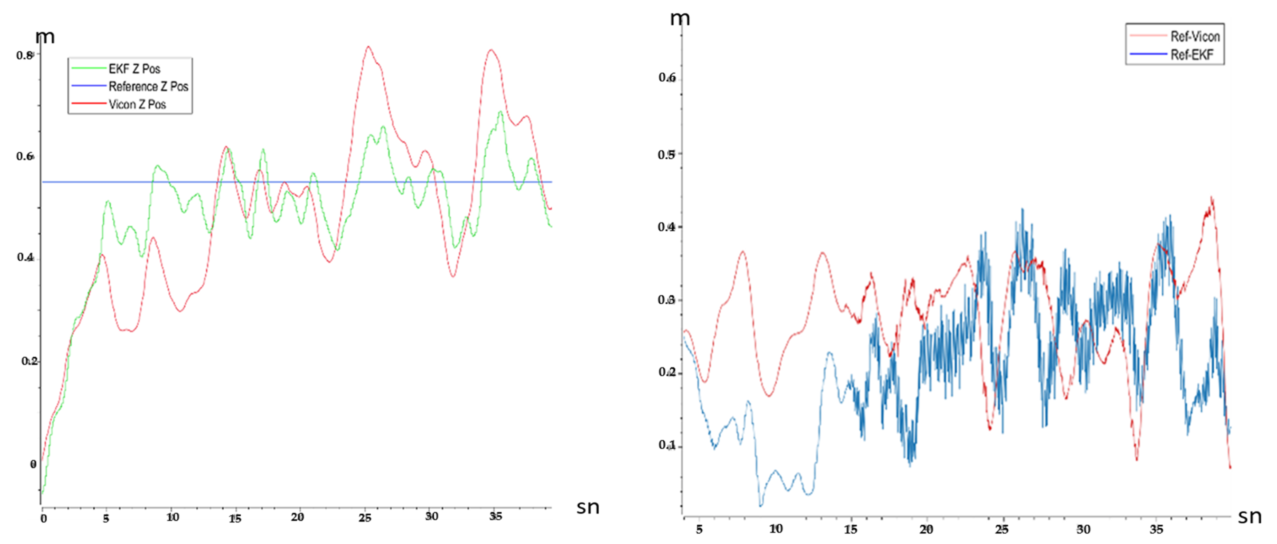
When looking at Figure 2 and Figure 3, it is easily noticeable that the X, Y, and Z positions obtained from the EKF are closer to the reference results than those obtained from the Vicon system. Additionally, Figure 3 depicts the differences between the EKF and Vicon in relation to their respective reference values. Upon examining the position error values in Table 1, it is evident that the average difference between the EKF and the reference is 0.205 m, while for the Vicon, this difference is 0.255 m. Moreover, when looking at the minimum and maximum errors, it is evident that the values obtained from the EKF are lower than those obtained from the Vicon system. In summary, through a numerical comparison of the results, it is apparent that the designed EKF algorithm provides better results compared to the Vicon positioning system.

4. Conclusions

In this study, position estimation was carried out by fusing raw distance data with the IMU using sensor fusion algorithms, specifically via the EFK. The fundamental structure of the designed algorithm incorporates a geometric approach. Firstly, a position calculation was derived from the geometric approach, and then the accuracy of this position was enhanced using accelerometer data and the EKF algorithm. The designed algorithm was transformed for incorporation into the C++ environment and integrated into an ROS. Real sensor data is used during the testing of the algorithm. Sensor data were collected using the ROS platform, and the algorithm was executed within the ROS to observe the obtained results. According to the results obtained, the designed EKF structure yielded more successful outcomes compared to the Vicon position system. These results are supported both graphically and by numerical tables.

Author Contributions

Conceptualization, T.B. and F.Ç.; Methodology, T.B.; Software, T.B.; Validation, T.B.; Data Acquisition, T.B; Formal Analysis, T.B.; investigation, T.B.; writing—original draft preparation, T.B.; writing—review and editing, T.B. and F.Ç; visualization, T.B.; supervision, F.Ç. All authors have read and agreed to the published version of the manuscript.

Funding

This research was partially financially supported by Istanbul Technical University, grant number 42754.

Institutional Review Board Statement

Not applicable.

Informed Consent Statement

Not applicable.

Data Availability Statement

Data are contained within the article.

Conflicts of Interest

The authors declare no conflicts of interest.

References

  1. Valavanis, K.P.; Vachtsevanos, G.J. UAV Applications: Introduction; Springer: Amsterdam, The Netherlands, 2015. [Google Scholar]
  2. Samad, T.; Bay, J.S.; Godbole, D. Network-centric systems for military operations in urban Terrain: The role of UAVs. Proc. IEEE 2007, 95, 92–107. [Google Scholar]
  3. Li, Z.; Liu, Y.; Walker, R.; Hayward, R.; Zhang, J. Towards automatic power line detection for a UAV surveillance system using pulse coupled neural filter and an improved Hough transform. Mach. Vis. Appl. 2010, 21, 677–686. [Google Scholar]
  4. Aiello, R.; Bar-Shalom, Y. Ultra-Wideband Technology for Precise Real-Time Location Systems. Proc. IEEE 2000, 88, 62–85. [Google Scholar]
  5. Heimovirta, E.; Salantera, S.; Röning, J. Real-Time Indoor Localization Using Ultra-Wideband Technology. In Proceedings of the 11th International Conference on Mobile and Ubiquitous Systems: Computing, Networking and Services, London, UK, 2–5 December 2014; pp. 265–274. [Google Scholar]
  6. Rhea, C.K. Accuracy and Precision of Vicon Motion Capture Systems for Tracking in 3D. Gait Posture 2004, 20, 332–335. [Google Scholar]
  7. Gentil, C.; de la Rouviere, S.; Elton, C. Vicon: A Computer Vision Solution for Reliable Real-Time 3D Motion Capture. J. NeuroEng. Rehabil. 2009, 6, 11. [Google Scholar]
  8. Benn, A.; Martin, A. Vicon Revue: Motion Capture Technology for Rehabilitation and Sports Medicine. Biomech. Med. Swim. 2004, IX, 122–126. [Google Scholar]
  9. Norrdine, A. An Algebraic Solution to the Multilateration Problem. In Proceedings of the 2012 International Conference on Indoor Positioning and Indoor Navigation, Sydney, Australia, 13–15 November 2012; pp. 1–4. [Google Scholar]
  10. Bodrumlu, T.; Caliskan, F. Indoor Position Estimation Using Ultrasonic Beacon Sensors and Extended Kalman Filter. Eng. Proc. 2022, 27, 16. [Google Scholar] [CrossRef]
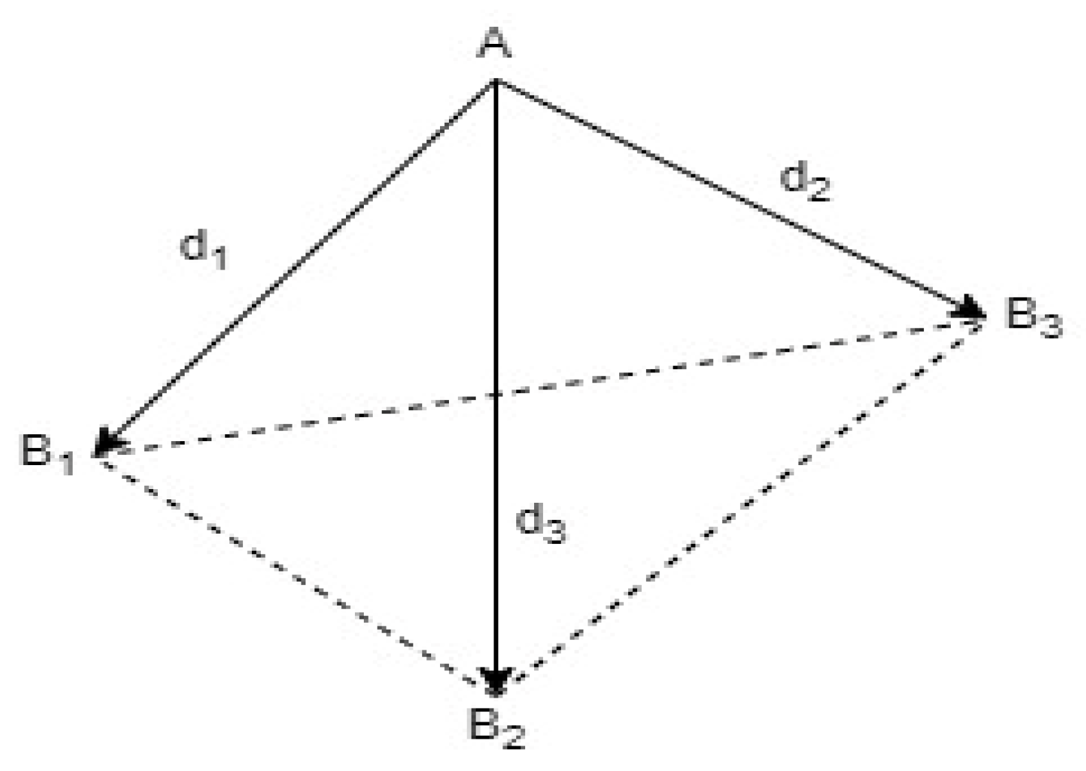
Figure 1. Reference points and interval measurements.
Engproc 58 00040 g001
Figure 2. X and Y positions (Vicon-EKF-Reference).
Engproc 58 00040 g002
Figure 3. Z position and Vicon and EKF differences from reference.
Engproc 58 00040 g003
Table 1. Position error values.
Minimum Error (m)Mean Error (m)Maximum Error (m)
Ref-EKF0.0190.2050.424
Ref-Vicon0.070.2550.441
Disclaimer/Publisher’s Note: The statements, opinions and data contained in all publications are solely those of the individual author(s) and contributor(s) and not of MDPI and/or the editor(s). MDPI and/or the editor(s) disclaim responsibility for any injury to people or property resulting from any ideas, methods, instructions or products referred to in the content.