
Fractal-Enhanced Microstrip Antennas: Miniaturization, Multiband Performance and Cross-Polarization Minimization for Wi-Fi Applications †

 ,
,
Abstract
:1. Introduction
- They have wideband and multiband frequency responses.
- They are reduced in size compared to traditional antennas.
- They have mechanical simplicity and strength.
- The properties of fractal antennas depend on geometry, not discrete additions.

| Paper Title | Author | Ref. No. | Method Used | Multiband/ Wideband |
|---|---|---|---|---|
| A New Super Wideband Fractal Microstrip Antenna | Abolfazl Azari | [8] | Octagonal fractal geometry | Wideband |
| Novel Wideband Planar Fractal Monopole Antenna | Mahdi Naghshvarian et al. | [9] | Penta-Gasket-Koch with partial ground | Wideband |
| Miniaturized UWB Monopole Microstrip Antenna Design by the Combination of Giuseppe Peano and Sierpinski Carpet Fractals | Homayoon Oraizi et al. | [11] | Hybrid fractal geometry with partial ground | Ultra-wideband |
| Dual-Band Antenna with Fractal-Based Ground Plane for WLAN Applications | Joan Gemio et al. | [15] | Ground plane fractal-based rather than a solid one | Multiband |
| Generalized Sierpinski Fractal Multiband Antenna | Jordi Romeu et al. | [16] | Derived fractal mod—P Sierpinski gaskets | Multiband |
1.1. Antenna Gain and Efficiency
1.2. Radiation Pattern
1.3. Return Loss
1.4. Directivity
2. Methodology
2.1. Sierpinski Carpet Geometry
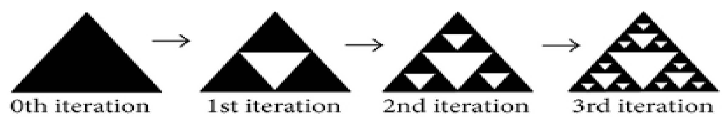
2.2. Sierpinski Gasket Geometry
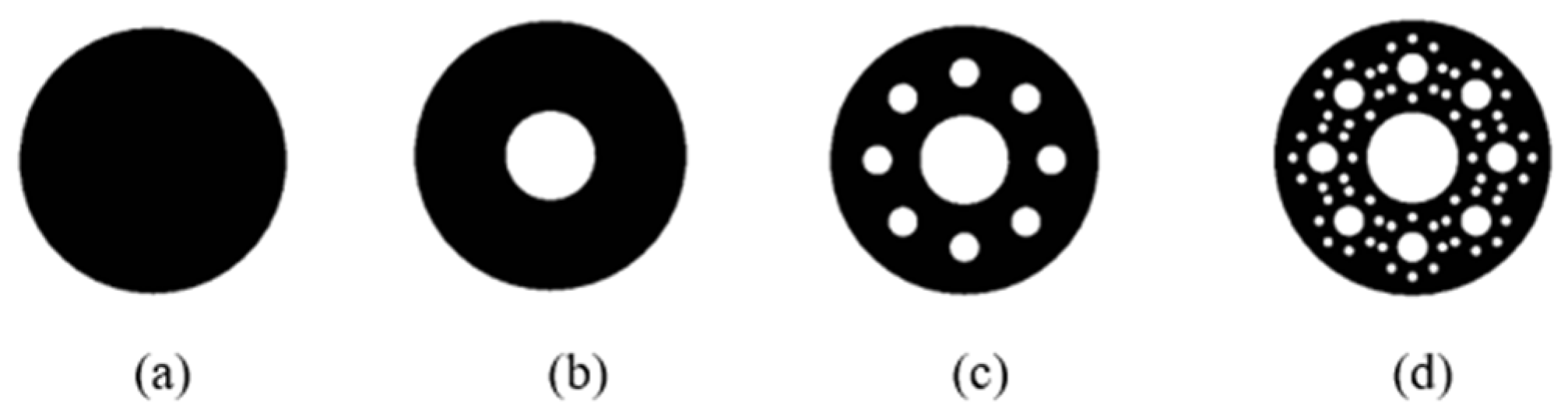
2.3. Sierpinski Circular Geometry
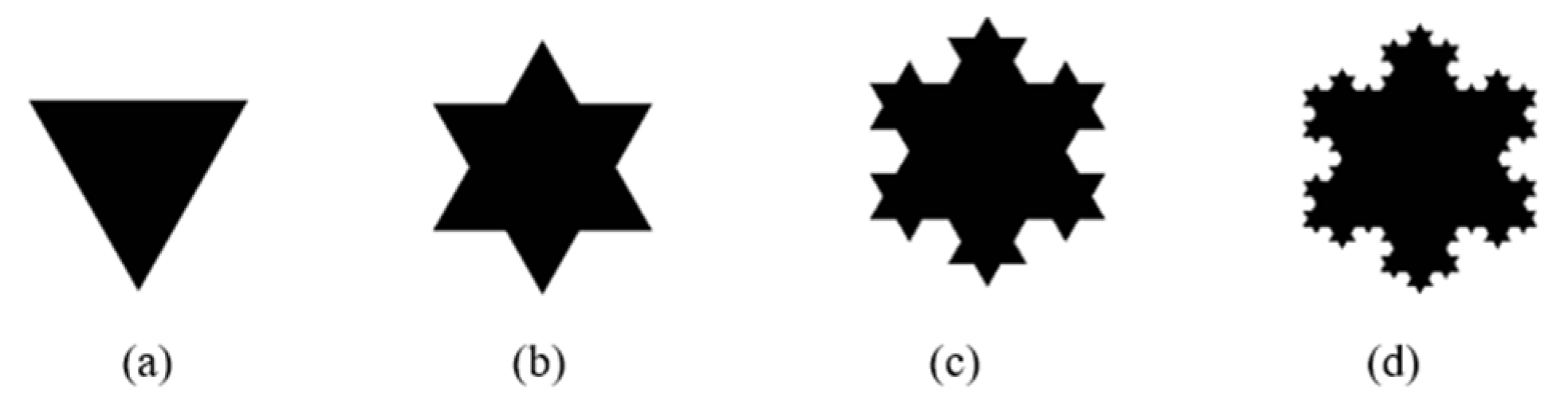
2.4. Koch Fractal Antenna
2.5. Antenna Design
3. Methodology
3.1. Sierpinski Carpet Antenna
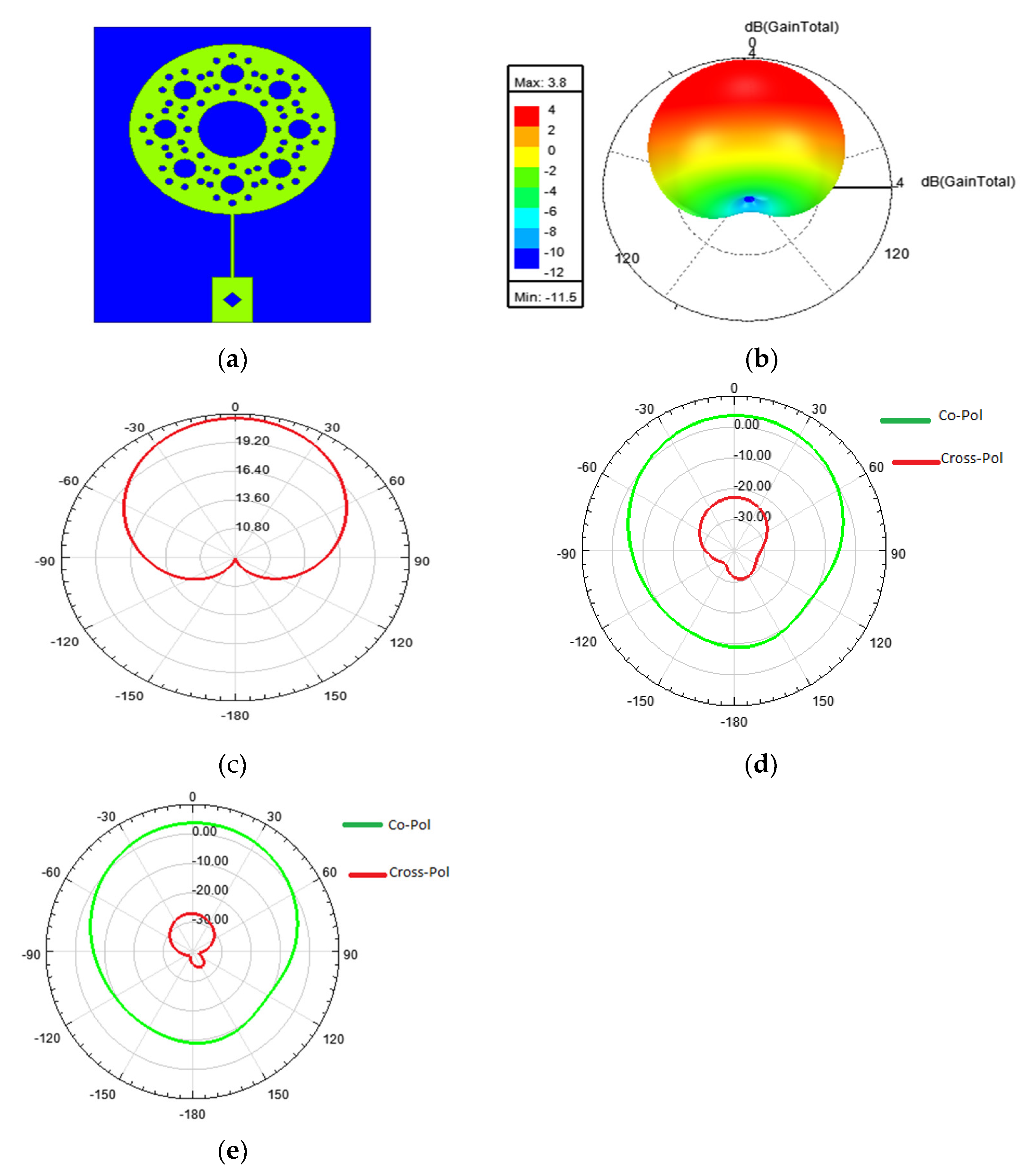
3.2. Sierpinski Circular Antenna
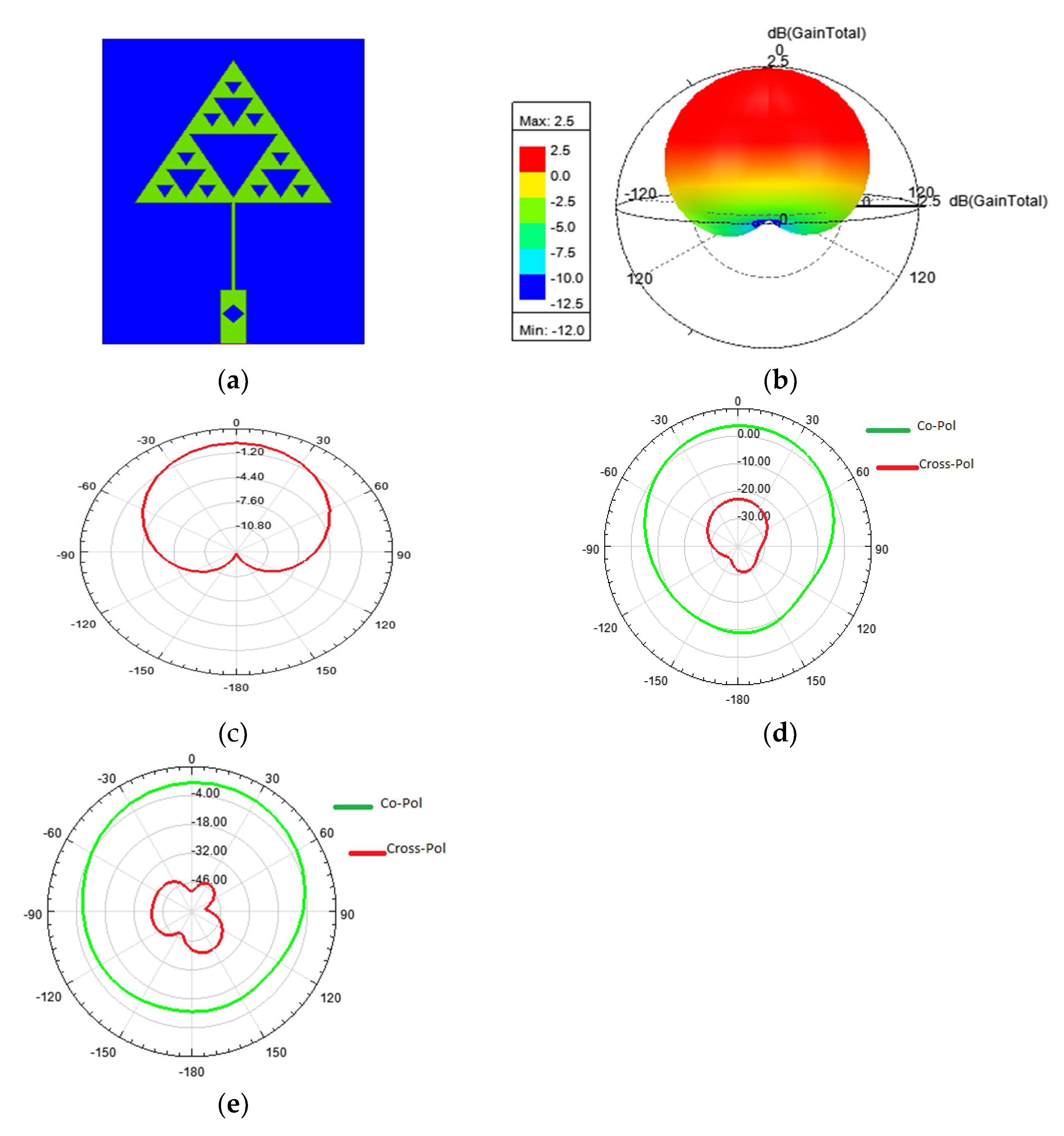
3.3. Sierpinski Gasket Antenna
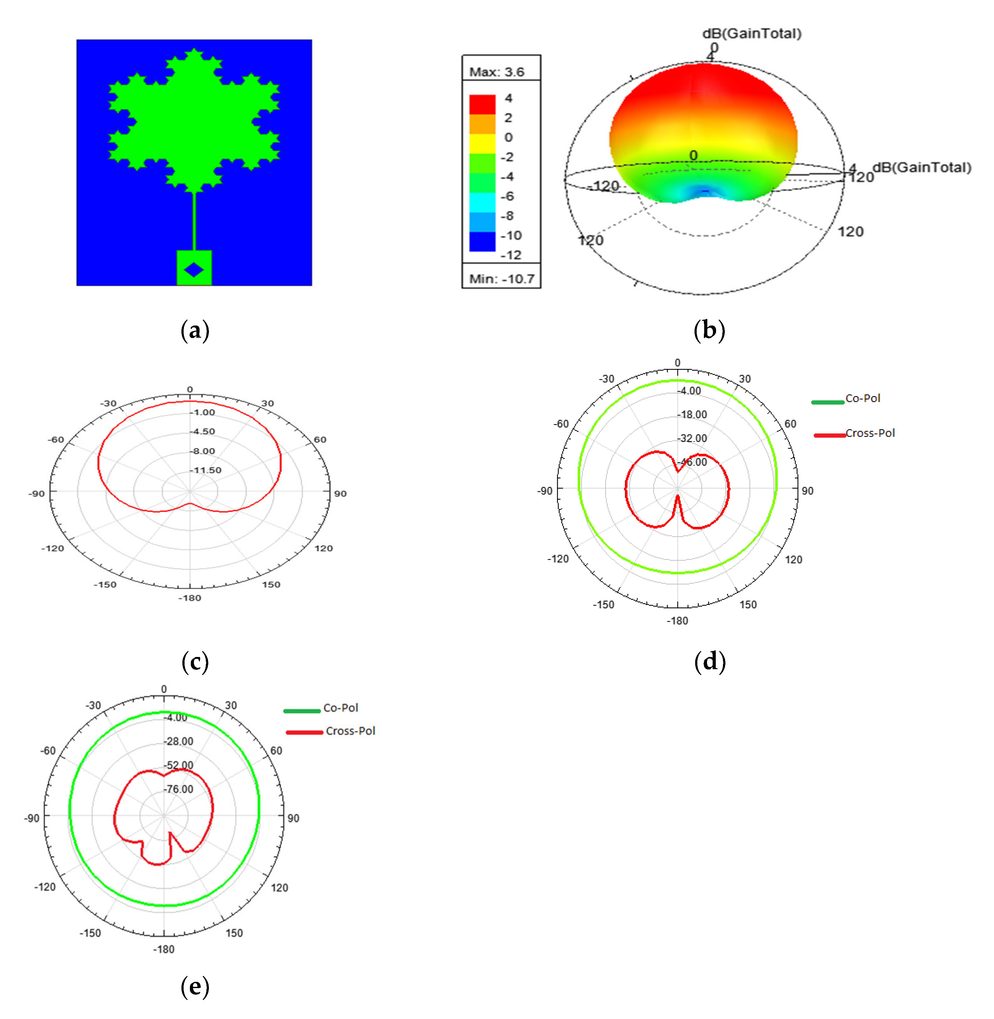
3.4. Koch Fractal Antenna
4. Conclusions
Author Contributions
Funding
Institutional Review Board Statement
Informed Consent Statement
Data Availability Statement
Acknowledgments
Conflicts of Interest
References
- Mandelbrot, B.B. The Fractal Geometry of Nature; WH Freeman: New York, NY, USA, 1983; Volume 1, pp. 1–14. [Google Scholar]
- Werner, D.H.; Ganguly, S. An overview of fractal antenna engineering research. IEEE Antennas Propag. Mag. 2003, 45, 38–57. [Google Scholar] [CrossRef]
- Amini, A.; Oraizi, H.; Zadeh, M.A. Miniaturized UWB Log-Periodic Square Fractal Antenna. IEEE Antennas Wirel. Propag. Lett. 2015, 14, 1322–1325. [Google Scholar] [CrossRef]
- Fractal-Shapes, S.; Chen, W.; Wang, G.; Zhang, C. Small-Size Microstrip Patch Antennas Combining. IEEE Antennas Wirel. Propag. Lett. 2009, 7, 738–741. [Google Scholar]
- Gorai, A.; Pal, M.; Ghatak, R. A compact fractal-shaped antenna for ultra-wideband and Bluetooth wireless systems with WLAN rejection functionality. IEEE Antennas Wirel. Propag. Lett. 2017, 16, 2163–2166. [Google Scholar] [CrossRef]
- Baliarda, C.P.; Romeu, J.; Cardama, A. The Koch monopole: A small fractal antenna. IEEE Trans. Antennas Propag. 2000, 48, 1773–1781. [Google Scholar] [CrossRef]
- Anguera, J.; Puente, C.; Soler, J. 2002 IEEE Antennas and Propagation Society International Symposium. IEEE Antennas Propag. Soc. AP-S Int. Symp. 2002, 1, 546–549. [Google Scholar]
- Azari, A. A new super wideband fractal microstrip antenna. IEEE Trans. Antennas Propag. 2011, 59, 1724–1727. [Google Scholar] [CrossRef]
- Naghshvarian-Jahromi, M. Novel wideband planar fractal monopole antenna. IEEE Trans. Antennas Propag. 2008, 56, 3844–3849. [Google Scholar] [CrossRef]
- Vargas, I.M.; Luy-Montejo, C.; Alcaide-Aranda, L.I.D.C.; Parks, D.I.G.; Cruz, Y.M.M.; Palacios-Garay, J.P.; Carmen Gonzales-Sánchez, A. Improved Butterfly Optimization Algorithm for Energy Efficient Antenna Selection Over Wireless Cellular Networks. J. Wirel. Mob. Netw. Ubiquitous Comput. Dependable Appl. 2023, 14, 121–136. [Google Scholar] [CrossRef]
- Oraizi, H.; Hedayati, S. Miniaturized UWB monopole microstrip antenna design by the combination of Giuseppe Peano and Sierpinski carpet fractals. IEEE Antennas Wirel. Propag. Lett. 2011, 10, 67–70. [Google Scholar] [CrossRef]
- Best, S.R. A multiband conical monopole antenna derived from a modified Sierpinski Gasket. IEEE Antennas Wirel. Propag. Lett. 2003, 2, 205–207. [Google Scholar] [CrossRef]
- Weng, W.C.; Hung, C.L. An H-fractal antenna for multiband applications. IEEE Antennas Wirel. Propag. Lett. 2014, 13, 1705–1708. [Google Scholar] [CrossRef]
- Oraizi, H.; Hedayati, S. Circularly polarized multiband microstrip antenna using the square and guiseppe peano fractals. IEEE Trans. Antennas Propag. 2012, 60, 3466–3470. [Google Scholar] [CrossRef]
- Gemio, J.; Granados, J.P.; Castany, J.S. Dual-band antenna with fractal-based ground plane for WLAN applications. IEEE Antennas Wirel. Propag. Lett. 2009, 8, 748–751. [Google Scholar] [CrossRef]
- Romeu, J.; Soler, J. Generalized Sierpinski fractal multiband antenna. IEEE Trans. Antennas Propag. 2001, 49, 1237–1239. [Google Scholar] [CrossRef]
- Uchida, N.; Ito, K.; Ishida, T.; Shibata, Y. Adaptive Array Antenna Control Methods with Delay Tolerant Networking for the Winter Road Surveillance System. J. Internet Serv. Inf. Secur. 2017, 7, 2–13. [Google Scholar]
- Tang, P.W.; Wahid, P.F. Hexagonal fractal multiband antenna. IEEE Antennas Wirel. Propag. Lett. 2004, 3, 111–112. [Google Scholar] [CrossRef]
- Prasad, R.H.; Vakula, D.; Chakravarthy, M. A novel fractal slot DGS microstrip antenna for Wi-Fi application. In Proceedings of the 2018 IEEE Indian Conference on Antennas and Propogation (InCAP), Hyderabad, India, 16–19 December 2018; pp. 1–4. [Google Scholar]
- Marzouk, M.; Rhazi, Y.; Nejdi, I.H.; Zerrad, F.E.; Saih, M.; Ahmad, S.; Ghaffar, A.; Hussein, M. Ultra-Wideband Compact Fractal Antenna for WiMAX, WLAN, C and X Band Applications. Sensors 2023, 23, 4254. [Google Scholar] [CrossRef] [PubMed]


| Structure | Size | Complexity | Operating Range | |
|---|---|---|---|---|
| MSA | Usually, radiating patch on one side and ground on the other side | Moderate | Moderate | Suitable for single- and narrow-band |
| Fractal Antenna | Based on self-similar structure | Small | Complex for higher-order iterations | Suitable for single/multiple/UWB applications |
| Antenna Geometry | Size | Resonating Frequency (GHz) | Return Loss (dB) | Gain (dB) |
|---|---|---|---|---|
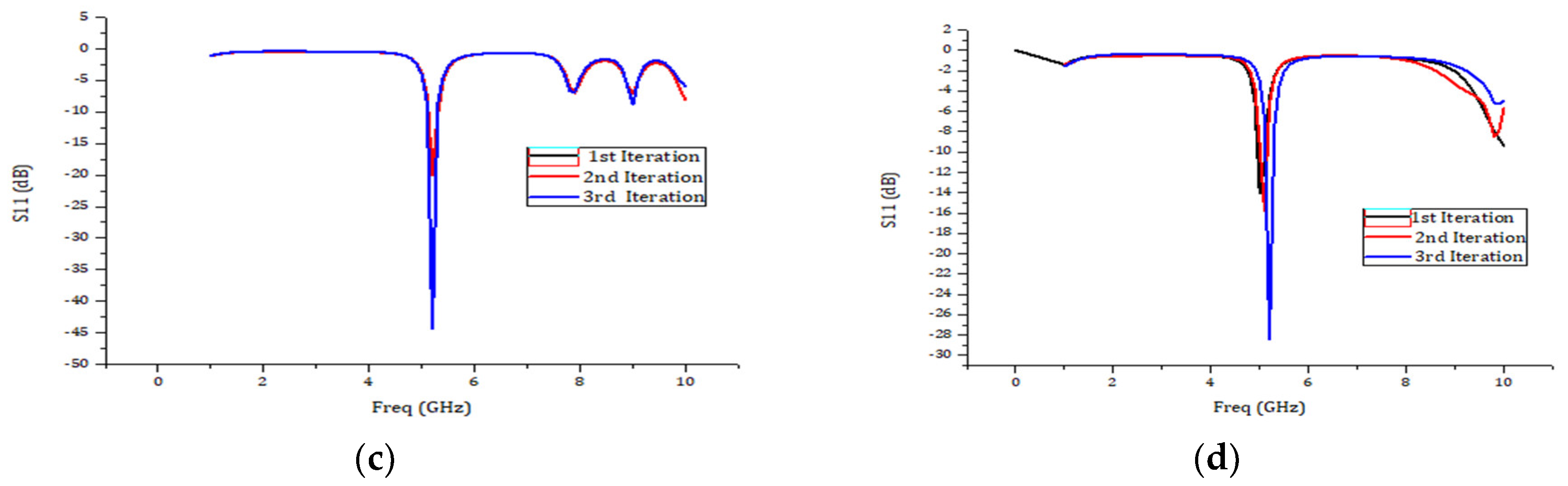
| Sierpinski carpet | 22 mm × 30 mm × 1.6 mm | 5.2 | −28.5 | 3.9 |
| Sierpinski gasket | 20 mm × 28 mm × 1.6 mm | 5.2 | −28.37 | 2.5 |
| Circular fractal | 20 mm × 26 mm × 1.6 mm | 5.2 | −40.1 | 3.8 |
| Koch fractal | 20 mm × 28 mm × 1.6 mm | 5.2 | −44.38 | 3.6 |
Disclaimer/Publisher’s Note: The statements, opinions and data contained in all publications are solely those of the individual author(s) and contributor(s) and not of MDPI and/or the editor(s). MDPI and/or the editor(s) disclaim responsibility for any injury to people or property resulting from any ideas, methods, instructions or products referred to in the content. |
© 2023 by the authors. Licensee MDPI, Basel, Switzerland. This article is an open access article distributed under the terms and conditions of the Creative Commons Attribution (CC BY) license (https://creativecommons.org/licenses/by/4.0/).
Share and Cite
Sanu, S.V.; Rodrigues, S.; Vallikkunnel, J.K.N.; Sivan, S.A. Fractal-Enhanced Microstrip Antennas: Miniaturization, Multiband Performance and Cross-Polarization Minimization for Wi-Fi Applications. Eng. Proc. 2023, 59, 127. https://doi.org/10.3390/engproc2023059127
Sanu SV, Rodrigues S, Vallikkunnel JKN, Sivan SA. Fractal-Enhanced Microstrip Antennas: Miniaturization, Multiband Performance and Cross-Polarization Minimization for Wi-Fi Applications. Engineering Proceedings. 2023; 59(1):127. https://doi.org/10.3390/engproc2023059127
Chicago/Turabian StyleSanu, Sanish Vaipel, Stephen Rodrigues, Jisha Krishnan Nair Vallikkunnel, and Sajitha Anpamattathil Sivan. 2023. "Fractal-Enhanced Microstrip Antennas: Miniaturization, Multiband Performance and Cross-Polarization Minimization for Wi-Fi Applications" Engineering Proceedings 59, no. 1: 127. https://doi.org/10.3390/engproc2023059127