Proceeding Paper

Investigation on the Acoustic Performance of Micro-Perforated Panel Integrated Coiled-Up Space Acoustic Absorber †

by
Damodaran Sanalkumar Govind Krishna
,
Parvathy Arun Leena
,
Abhinav Karottuthundathil
,
Ashidha Mohammed
,
Mahesh Kavungal
and
Mini Rema Sahadevan
*
Department of Mechanical Engineering, College of Engineering Trivandrum, Thiruvananthapuram 695016, Kerala, India
*
Author to whom correspondence should be addressed.
Presented at the International Conference on Recent Advances in Science and Engineering, Dubai, United Arab Emirates, 4–5 October 2023.
Eng. Proc. 2023, 59(1), 168; https://doi.org/10.3390/engproc2023059168
Published: 17 January 2024
(This article belongs to the Proceedings of Eng. Proc., 2023, RAiSE-2023)

Abstract

:
Recently, increased attention has been given to minimize the effects of noise pollution on living beings. The attenuation and manipulation of sound waves with low-frequency components are quite difficult with traditional absorbers due to inherent properties induced by large wavelengths and yet are particularly critical to modern designs. In this study, a parallel arrangement of a coiled-up space cavity and micro-perforated panel (MPP) is considered as the absorber configuration. The coiled-up space consists of a front panel with an orifice and a rigid backing panel enclosing an arch-shaped concentric channel. The entire coiled-up space length is provided with two varying cross-sections. By this arrangement, the sound path is squeezed into a reasonably small volume enabling sound absorption at low frequencies. A thin panel with numerous perforations is the main constituent of MPP. It is backed by an air cavity and terminated by a rigid backing. Here in this configuration, micro perforations are provided on the front panel of the coiled-up space, which ensures simultaneous entry of acoustic waves into the micro-perforations and coiled-up space structure. The absorption characteristics of the present configuration are studied numerically and analytically. The combined structure with parallel combination of coiled-up space and MPP resulted in the abatement of more than 70% of sound in the frequency range of 321 Hz to 853 Hz. The present absorber has only a 5.5 cm thickness, which is subwavelength   λ 19 also.

1. Introduction

Low-frequency (LF) noise pollution has a profound impact on the lives and well-being of all living organisms [1,2,3] and may lead to lethal consequences if gone unnoticed. LF vibrations are often unavoidable in our day-to-day life as the main sources are as common as road vehicles, compressors, and air-conditioning units [4,5,6]. Also, the usual background noise prevailing in urban environments and noise emitted by sources like wind turbines, presses, airports, aircraft, industrial machinery, ships, etc., lies in low-frequency regions [7,8,9]. Studies show that prolonged exposure to LF vibrations leads to problems with sleep, affects physical and mental performance, and can cause psychophysical stress, cardiovascular issues, etc. [10,11,12]. Also, the decreased rate of bioturbation in LF-noise-exposed environments is evidence that it is potentially harmful to the proper maintenance of the ecosystem [8]. However, low-frequency noise pollution may not seem as alarming as mainstream general pollution issues. A large number of studies have focused on the health and environmental impact of noise, but only a few have focused exclusively on the impacts due to low-frequency noise. Proper focus is needed on the area to assess the impact and find necessary solutions.
Traditional absorbers such as foams and fibers are not suitable to curb low- to mid-frequency sound due to their high penetration and thickness constraints. The Helmholtz resonator (HR) is a low-frequency absorber, which is a kind of air spring oscillator. By tuning the configuration and by arranging it in parallel, the tradeoff between wider bandwidth and less space requirement can be overcome [7]. Another type of sound absorber that is commonly used to attenuate mid- to high-frequency sound waves is a Microperforated Panel (MPP). The panel is a thin sheet of material with small perforations that allow sound waves to pass through. Behind the panel, there is typically an air gap or cavity that acts as a resonator, and it is followed by a rigid backing. An MPP has superior absorption properties without the demerits of a porous material and is also preferable from an aesthetic point of view. Integrating a Helmholtz resonator and micro-perforated panel can result in low to mid-frequency sound absorption with less thickness and a much wider bandwidth [8].
A more recent trend in sound absorbers is acoustic metamaterials [9,13,14,15,16,17,18]. Pavan et al. [9] proposed a porous labyrinthine acoustic metamaterial which exhibited near-perfect sound absorption at low-frequency regions. Coiled-up space refers to resonators with wrapped or coiled chambers to produce a more compact structure [13]. As a result, the absorption band can be shifted to very low frequencies, allowing for the efficient use of space. By tuning the geometric parameters of the channel (length or cross-sectional area), the width and position of the absorption band can be adjusted. The coiled-up space dissipates sound energy through mechanical losses in the tubing and thereby reduces the amount of sound that is reflected back into the room. When used in combination with other sound-absorbing materials, such as MPP, the coiled-up space can help to create a more acoustically balanced environment, particularly in noisy spaces such as recording studios or concert halls [13].
In the present study, the absorption characteristics of a subwavelength-thick absorber, which is an integration of coiled-up space and a microperforated panel, are investigated. Numerical analysis and analytical modeling of the absorber are performed to analyze its absorption behavior. The research in this study will contribute to advancements in low-frequency broadband sound absorbers.

2. Methodology

2.1. Geometric Model

In this study, a hybrid absorber with a parallel arrangement of a MPP and a coiled-up space is considered. The configuration has a ring-shaped MPP backed by a cavity followed by a sound-hard boundary. It is arranged in front of the compartment containing coiled-up space and each coiled-up space is an arch-like channel. Sound waves enter the coiled-up channels through an orifice provided in conjunction with the MPP. The hybrid absorber is schematically given in Figure 1. When sound passes through the absorber, a portion of sound goes through the microperforated panel and the rest passes through the orifice into the coiled-up space. The simultaneous entry of sound into the MPP and coiled- up space makes it a parallel arrangement. The dimensions of the MPP and coiled-up space considered in the configuration are given in Table 1 and Table 2, respectively.

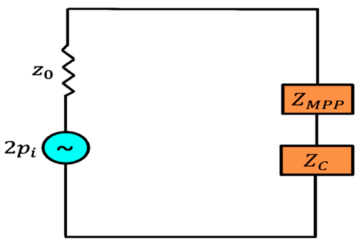
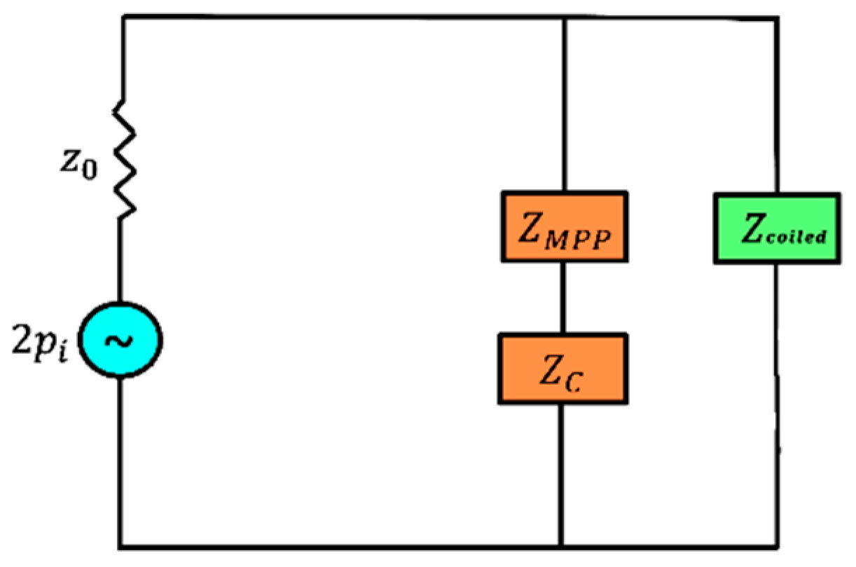
2.2. Numerical Model

The absorber inside an impedance tube is numerically modeled using COMSOL Multiphysics software. The domain inside the coiled cavity of the absorber is modeled using narrow region acoustics. Air with density, ρ = 1.24 kg/m3, and sound velocity, c = 346 m/s, are selected as the medium inside the impedance tube. The wall of the impedance tube is considered as sound-hard. The receiving end of the impedance tube is taken as a sound rigid surface. The schematic diagram of the impedance tube model is given in Figure 2. The value of porosity is taken as one for the model and the tortuosity is one as the geometry does not include any twisted shape. The governing equation for wave propagation is the Helmholtz equation [7], which is the acoustic wave equation in the frequency domain,
. 1 ρ p k 2 p ρ = 0 ,
where p is the acoustic pressure, ρ stands for density, and wave number k is the ratio between angular frequency and speed of sound.
The pressure response from the two microphones p 1 and p 2 are extracted after the wave is allowed to propagate through the model. Using those pressures, transfer function H 12 is determined as [20],
H 12 = p 2 p 1 = e i k x 2 + R e i k x 2 e i k x 1 + R e i k x 1
where x1 and x2 are the microphone positions from the source. The coefficient of reflection R is given by the equation
R = H 12 e i k s e i k s H 12 e 2 i k x 1
The absorption coefficient α is determined from the reflection coefficient as per the relation
α = 1 R 2
A unit amplitude plane wave is given as the excitation from the left side of the impedance tube. As per ISO 10534-2 standard, within the frequency range of 0–1500 Hz, the sound pressure at the two microphone positions is taken in each 5 Hz increment. Sound absorption under normal incidence is calculated. Absorption coefficient v/s frequency is plotted in MATLAB. The parameters taken for the simulation are given in Table 1 and Table 2. The Narrow Region Acoustics module, a specialized tool for analyzing acoustic waves in small cavities, is used to analyze the coiled-up space cavity, which accounts for the losses induced by viscous and thermal boundary layers. To analyze the interior condition of a micro-perforated panel (MPP) with a single plate, the plate is defined as a solid object with a thickness of 2 mm. The holes in the plate are taken as cylindrical perforations with a diameter of 2 mm. The required porosity value is given and an air cavity of the required thickness is specified.

2.3. Analytical Model

An analytical calculation is conducted for validation of the obtained results from the numerical simulation. All the calculations are performed in MATLAB software. The codes for respective configurations are formulated for plotting the absorption coefficient against the frequency graph and also for overplotting the results obtained from numerical simulation and those from the analytical calculation for comparison.
The visco-thermal acoustic theory is used to consider the losses in the coiled-up space. It deals with the effects of viscosity and heat conduction in the fluid medium within the coiled cavity. For the MPP, the electro-acoustic analogy is considered to find the impedance. In electro-acoustic analogy, the acoustic behavior of the MPP is modeled using an analogous electric circuit. The analytical method is used to validate the numerical method and also to geometrically tune the absorber to obtain the parameters that yield the best performance. For the analytical calculation of coiled-up space, the coiled-up tubes are considered as long, straight tubes in series. As shown in Figure 3, the tubes which are axially joined are uncoiled into straight tubes for analyses purposes. For the equivalent straight-tube model, the cross-section area of the coiled-up space, which is originally taken as rectangle, is converted to a circular cross-section of the same area. Also, the sound path length inside the coiled space is taken as the equivalent length of the tubes. The path length of the sound is traced according to Chen’s model [13].
The total acoustic impedance of the tube 1 that is backed with rigid wall is
Z 1 = j Z 1 C c o t   k 1 L t 1 ,
where k 1 = ω ρ e q 1 K e q 1 is the effective propagation constant of tube 1. It is the measure of change in amplitude as the phase moves in a particular direction. Z 1 C = ρ e q 1 K e q 1     is the characteristic impedance, which is the ratio of effective sound pressure at a particular position and the effective particle velocity there. Here, ρ e q 1 and K e q 1 are the effective density and effective bulk modulus of air inside the tube.
  ρ e q 1 = ρ F ϑ     ,
and
K e q 1 = γ P 0 γ γ 1 F ϑ γ ,    
where γ   is the ratio of specific heats, ρ is the air density, and P 0 is the atmospheric pressure of air. ϑ = μ 0 k 0 and ϑ = k 0 ρ 0 C v where,   μ 0 , C v , and k 0 represent the viscosity of air, heat capacity at constant volume, and thermal conductivity, respectively.
  • Here, the function F(x) is
F x = 1 4 j ω x 1 2 G [ d 1 j ω x 1 2 2 ] / d 1   .  
In this, the function G is the ratio between Bessel functions of the first kind of order one and order zero.
G ζ = J 1 ( ζ ) J 0 ( ζ )         ,
where J 1 and J 0 are the Bessel functions of order one and zero, respectively.
The characteristic impedance of the coiled-up space is also found using the relation
Z 2 = Z c 1 j Z 11 c o t ( k 2 L t 2 ) + Z c 1 Z 11 j Z c 1 c o t ( k 2 L t 2 )           ,
where Z 11 = Z 1 ϕ 1   and   ϕ 1 = A 1 A 2   ,   where A 1 and A 2 are the area of cross-section of the first and second tube, respectively, and k 2 = ω ρ e q 2 K e q 2   ,   is the effective propagation constant of the second tube. The impedance of the coiled-up space Z c o i l e d = Z 2 ϕ 2 , where ϕ 2 is defined as the porosity of the panel. Using the total impedance of the coiled-up space and the characteristic acoustic impedance of air Z 0 , the absorption coefficient is determined as
α = 1 Z c o i l e d Z 0 Z c o i l e d + Z 0 2             .
The equivalent electro-acoustic circuit of MPP is given in Figure 4.
The acoustic impedance of an MPP with plate thickness t and cavity depth l is Z M P P = Z 0 R M P P + j X M P P . Here, R M P P and X M P P are the normalized specific acoustic resistance and reactance, respectively. The normalized specific acoustic resistance is given by [21],
R M P P = 32 t η σ ρ c d 2 1 + k m 2 32 + 2 8 k m d t ,
where k m = d 2 ρ ω η is the perforation constant. σ is the ratio between perforated area and the area of the panel, which is called porosity, and ω is the angular frequency.
  • The normalized specific acoustic reactance is
X M P P = ω c t σ 1 + 1 9 + k m 2 2 + 0.85 d t .
The acoustic impedance of the rigid back cavity is Z C = j z 0 c o t k l ,   where l is the thickness of the backing cavity of the MPP. From the electro-acoustic circuit shown in Figure 4, the total impedance of the MPP is Z M P P   t o t a l = Z M P P + Z C and the absorption coefficient of the MPP is determined using the equation
α = 1 Z M P P   t o t a l Z 0 Z M P P   t o t a l + Z 0 2     .
The required MPP model is geometrically tuned using the analytical method to obtain the optimum parameters of porosity, backing cavity length, perforation radius, etc. For the hybrid absorber of the MPP and coiled-up space, the electro-acoustic circuit is as depicted in Figure 5. The total impedance is calculated as per the relation
Z A B S O R B E R = 1 1 Z M P P   t o t a l + 1 Z c o i l e d
and the absorption coefficient of the hybrid absorber is
α A B S O R B E R = 1 Z A B S O R B E R Z 0 Z A B S O R B E R + Z 0 2     .

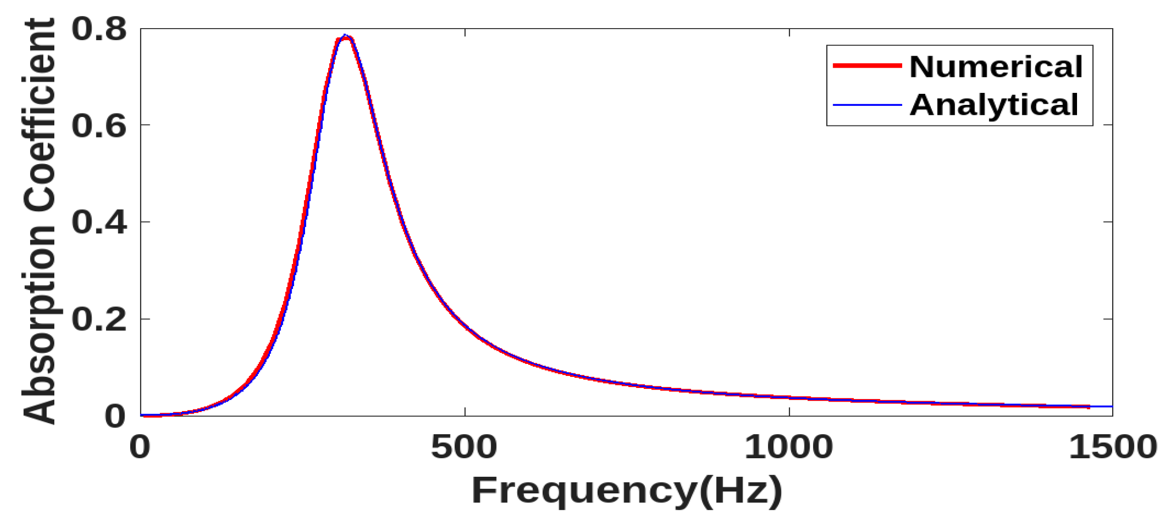
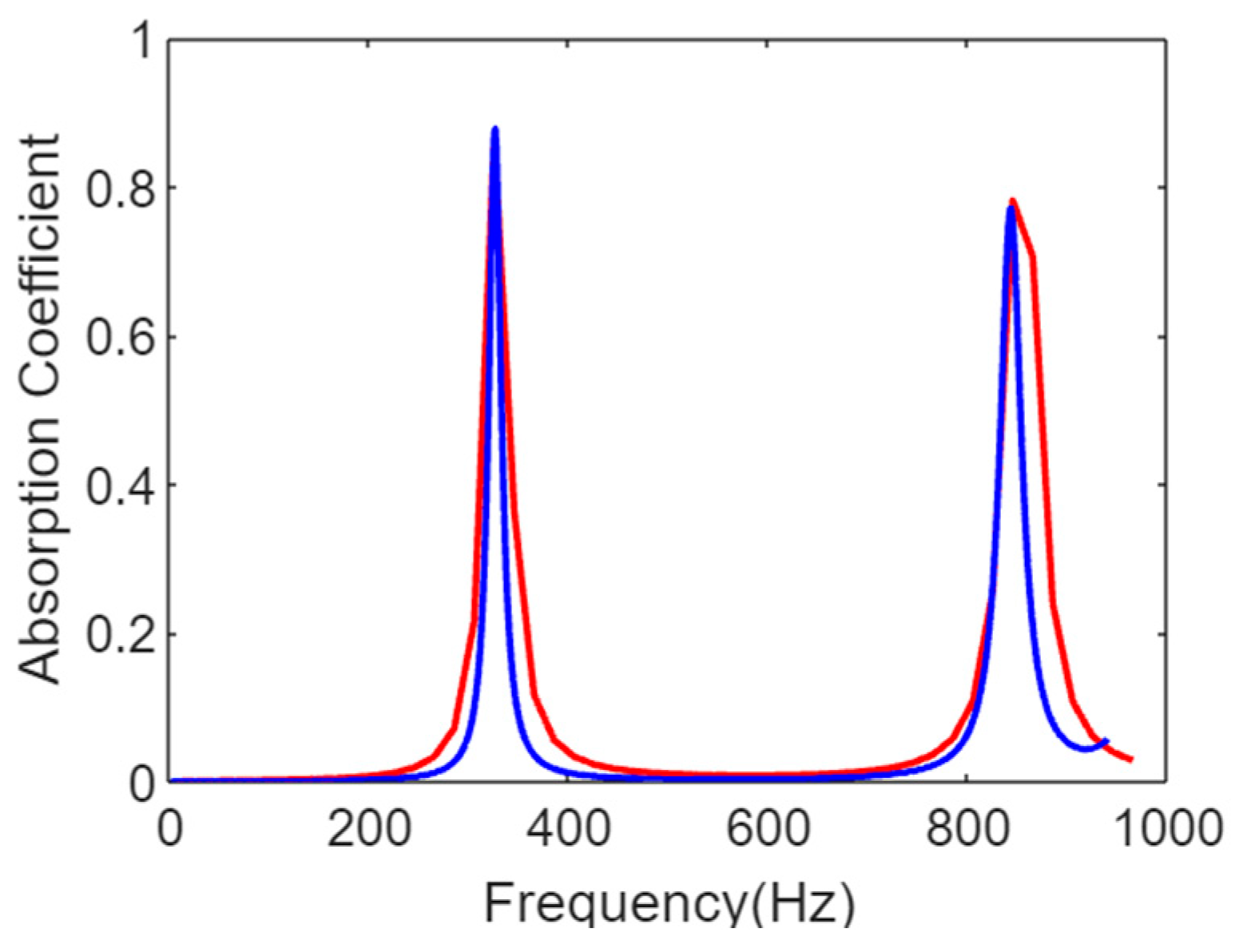
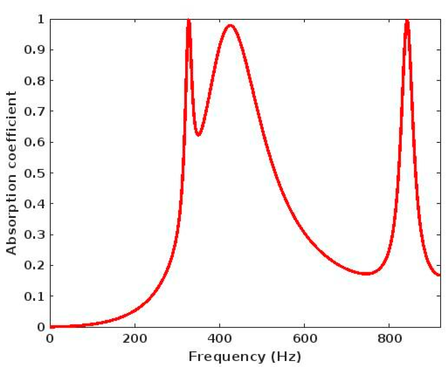
3. Results and Discussion

The results obtained from the numerical simulation and analytical calculations are analyzed separately for the coiled-up space and the MPP. After that, the results obtained for the hybrid model are considered. Figure 6 shows the analytical results of the MPP, which agree perfectly with the numerical simulations. A broader absorption curve is observed with a peak at 314 Hz with an absorption coefficient of 0.784.
For coiled-up space, two resonant peaks are observed: one at around 300 Hz and the other around 900 Hz. From Figure 7, it is seen that at low frequencies the analytical and numerical results match perfectly with each other. But a considerable variation is observed in the high-frequency range. In the analytical calculations, the effect of bend is not considered and the propagation path length is approximated. There are possible causes of variation. Two peaks are observed with decreasing absorption coefficients.
The hybrid absorber is the integration of the MPP and coiled-up space. When they are integrated, the absorption spectrum extends from around 300 Hz to 900 Hz. But a large antiresonance is also observed around 800 Hz. The absorption coefficient vs. frequency graph of the final absorber before tuning is shown in Figure 8.
Three peaks can be observed from the absorption characteristics. The first and last peaks belong to the coiled-up cavity and the second peak belongs to the MPP. About 98% of the absorption is achieved at very low frequencies but the peak obtained is narrow and the overall performance of the absorber is affected by the anti-resonance. So, the absorber is further tuned by varying geometric parameters to obtain a desirable result. Hence, the single cross-section of the MPP is divided into four cross-sections with varying porosities. The dimensions of the tuned hybrid absorber are given in Table 3 and Table 4. The absorption coefficient vs. frequency graph of the tuned absorber is shown in Figure 9.
Tuning of the parameters resulted in a wide bandwidth of absorption, with the absorption coefficient above 0.7 for the entire frequency range (from 321 Hz to 853 Hz). Distinct peaks can be observed in the absorption curve. The first peak corresponds to the first channel of the coiled-up space with an absorption coefficient of 0.996 at a resonant frequency of 327 Hz. Four cross-sections of the MPP result in four peaks and the last peak corresponds to the second channel of coiled-up space, with an absorption coefficient of 0.976 at 842 Hz. Thus, by integrating the coiled-up space and the MPP, broadband noise absorption is achieved in the low- to mid-frequency region. The proposed absorber with sub wavelength thickness λ 19 is highly promising for absorbing low- to mid-frequency noise.

4. Conclusions

The hybrid absorber is designed by integrating coiled-up space and an MPP for achieving low- to mid-frequency sound absorption. The usage of coiled-up space decreased the thickness of the absorber and it also facilitated absorption in the low-frequency regions. By integrating both of these configurations, a broadband of absorption is obtained. The absorber has more than 70% absorption from 321 Hz to 853 Hz. The slight variation between the analytical and numerical results of the hybrid absorber is due to the approximation of sound path length and the effect of bend at higher frequencies. The present configuration can be considered as a better choice for the attenuation of broadband sound in the low-mid frequency region. Acoustic panels manufactured with these hybrid absorber units, in parallel arrangements, can be used for the attenuation of low- to mid-frequency sound in large rooms and other acoustic environments.

Author Contributions

Conceptualization, M.K. and M.R.S.; methodology, D.S.G.K., P.A.L., A.K., A.M. and M.K.; software, D.S.G.K., P.A.L., A.K. and A.M.; validation, D.S.G.K., P.A.L., A.K. and A.M.; analysis, D.S.G.K., P.A.L., A.K., A.M. and M.K.; writing—original draft preparation, D.S.G.K., P.A.L., A.K. and A.M.; writing—review and editing, D.S.G.K., P.A.L., A.K., A.M. and M.R.S.; supervision, M.R.S. All authors have read and agreed to the published version of the manuscript.

Funding

This research received no external funding.

Institutional Review Board Statement

Not applicable.

Informed Consent Statement

Not applicable.

Data Availability Statement

Data are contained within the article.

Acknowledgments

The authors would like to thank the Government of Kerala and AICTE for the support they rendered.

Conflicts of Interest

The authors declare no conflicts of interest.

References

  1. Leventhall, H.G. Low frequency noise and annoyance. Noise Health 2004, 6, 59–72. [Google Scholar]
  2. Berglund, B.; Hassmen, P.; Job, R.F. Sources and effects of low frequency noise. J. Acoust. Soc. Am. 1996, 99, 2985–3002. [Google Scholar] [CrossRef] [PubMed]
  3. Araujo, A.; Neto, P.F.; Torres, S.L.; Remoald, P. Low frequency noise and its main effects on human health-A review of the literaturebetween 2016 and 2019. Appl. Sci. 2020, 10, 5205. [Google Scholar] [CrossRef]
  4. Miedema, H.; Oudshoorn, C. Annoyance from transportation noise: Relationships with exposure metrics DNL and DENL and their confidence intervals. Environ. Health Perspect. 2001, 109, 409–416. [Google Scholar] [CrossRef] [PubMed]
  5. Mehdi, M.R.; Kim, M.; Seong, J.C.; Arsalan, M.H. Spatio-temporal patterns of road traffic noise pollution in Karachi, Pakistan. Environ. Int. 2011, 37, 97–104. [Google Scholar] [CrossRef] [PubMed]
  6. Licitra, G.; Fredianelli, L.; Petri, D.; Vigotti, M.A. Annoyance evaluation due to overall railway noise and vibration in Pisa urban areas. Sci. Total Environ. 2016, 568, 1315–1325. [Google Scholar] [CrossRef] [PubMed]
  7. Mahesh, K.; Mini, R.S. Investigation on the Acoustic Performance of Multiple Helmholtz Resonator Configurations. Acoust. Aust. 2021, 49, 355–369. [Google Scholar] [CrossRef]
  8. Mahesh, K.; Mini, R.S. Theoretical investigation on the acoustic performance of Helmholtz resonator integrated microperforated panel absorber. Appl. Acout. 2021, 178, 108012. [Google Scholar] [CrossRef]
  9. Pavan, G.; Singh, S. Near-perfect sound absorptions in low-frequencies by varying compositions of porous labyrinthine acoustic metamaterial. Appl. Acoust. 2022, 198, 108974. [Google Scholar] [CrossRef]
  10. Dratva, J.; Phuleria, H.C.; Foraster, M.; Gaspoz, J.M.; Keidel, D.; Künzli, N.; Liu, L.-J.S.; Pons, M.; Zemp, E.; Gerbase, M.W. Transportation noise and blood pressure in a population-based sample of adults. Environ. Health Perspect. 2012, 120, 50–55. [Google Scholar] [CrossRef] [PubMed]
  11. Babisch, W.; Ising, H.; Gallacher, J. Health status as a potential effect modifier of the relation between noise annoyance and incidence of ischaemic heart disease. Occup. Environ. Med. 2003, 60, 739–745. [Google Scholar] [CrossRef] [PubMed]
  12. Muzet, A. Environmental noise, sleep and health. Sleep Med. Rev. 2007, 11, 135–142. [Google Scholar] [CrossRef] [PubMed]
  13. Chen, J.; Chung, Y.; Wang, C.; Lo, W.; Liu, C.; Yu, C.; Chang, I.; Lin, T. Ultrathin arch-like labyrinthine acoustic metasurface for low-frequency sound absorption. Appl. Acoust. 2023, 202, 109142. [Google Scholar] [CrossRef]
  14. Langfeldt, F.; Khatokar, A.; Gleine, W. Plate-type acoustic metamaterials with integrated Helmholtz resonators. Appl. Acoust. 2022, 199, 109019. [Google Scholar] [CrossRef]
  15. Lu, Q.; Li, X.; Zhang, X.; Lu, M.; Chen, Y. Perspective: Acoustic Metamaterials in Future Engineering. Engineering 2022, 17, 22–30. [Google Scholar] [CrossRef]
  16. Gaafer, F.N. Broadband Low-Frequency Sound Absorption via a Hexagonal Acoustic Metamaterial in the Honeycomb Structure. Kuwait J. Sci. 2022, 49, 1–11. [Google Scholar] [CrossRef]
  17. Chang, L.; Jiang, A.; Rao, M.; Ma, F.; Huang, H.; Zhu, Z.; Zhang, Y.; Wu, Y.; Li, B.; Hu, Y. Progress of low-frequency sound absorption research utilizing intelligent materials and acoustic metamaterials. RSC Adv. 2021, 11, 37784–37800. [Google Scholar] [CrossRef] [PubMed]
  18. Hongyu, C.; Chengtao, L.; Haoming, H. Research on Low-Frequency Noise Control Based on Fractal Coiled Acoustic Metamaterials. Shock Vib. 2022, 2022, 1–14. [Google Scholar]
  19. Wolkesson, M. Evaluation of Impedance Tube Methods—A Two Microphone In-Situ Method for Road Surfaces and the Three Microphone Transfer Function Method for Porous Materials. Master’s Thesis, Chalmers University of Technology, Goteborg, Sweden, 2013. [Google Scholar]
  20. Mahesh, K.; Mini, R.S. Numerical Investigation on the Absorption Characteristics of Helmholtz Resonator Based Absorber with Neck Opening on the Wall, In Proceedings of the International Conference on Emerging Trends in Engineering Yukthi-2021, Kozhikode, India, 24–26 September 2021.
  21. Maa, D.Y. Theory and design of microperforated panel sound-absorbing constructions. Sci. Sin. 1975, 18, 55–71. [Google Scholar]
Figure 1. CAD model of the hybrid absorber: (a) assembled isometric view and (b) exploded view.
Engproc 59 00168 g001
Figure 2. Impedance tube model with two microphones [19].
Engproc 59 00168 g002
Figure 3. Equivalent straight tube model of coiled-up space.
Engproc 59 00168 g003
Figure 4. Electro-acoustic model of MPP.
Engproc 59 00168 g004
Figure 5. Electro-acoustic model of hybrid absorber.
Engproc 59 00168 g005
Figure 6. Absorption coefficient vs. frequency plot of MPP from numerical simulation and analytical calculations (parameters are given in Table 2).
Engproc 59 00168 g006
Figure 7. Absorption coefficient vs. frequency plot of coiled-up space from numerical simulation and analytical calculations (parameters given in Table 1).
Engproc 59 00168 g007
Figure 8. Absorption coefficient vs. frequency plot of the hybrid absorber.
Engproc 59 00168 g008
Figure 9. Absorption coefficient vs. frequency plot of the hybrid absorber from numerical simulation and analytical calculation after tuning.
Engproc 59 00168 g009
Table 1. Geometric parameters of the coiled-up space.
Width Channel 1Length Channel 1Width Channel 2Length Channel 2HeightWall Thickness
11 mm264 mm8 mm102 mm12 mm3 mm
Table 2. Geometric parameters of the microperforated panel.
Diameter of PanelThickness of PanelDiameter of PerforationCavity HeightPorosity
100 mm1 mm1 mm40 mm0.08
Table 3. Geometric parameters of coiled-up cavity in the hybrid absorber after tuning. The height of the coiled cavity is 12 mm and the wall thickness is 3 mm.
Coiled CavityWidth (mm)Length (mm)
111264
28102
Table 4. Geometric parameters of MPP in the hybrid absorber after tuning. The diameter of the micro-perforated panel is 100 mm and the backing cavity thickness is 40 mm.
PanelThickness (mm)Diameter of Holes (mm)Porosity of Panel
12.71.30.018
23.81.70.015
31.510.02
41.32.50.006
Disclaimer/Publisher’s Note: The statements, opinions and data contained in all publications are solely those of the individual author(s) and contributor(s) and not of MDPI and/or the editor(s). MDPI and/or the editor(s) disclaim responsibility for any injury to people or property resulting from any ideas, methods, instructions or products referred to in the content.

