
Optimizing and Analyzing a Centrifugal Compressor Impeller for 50,000 rpm: Performance Enhancement and Structural Integrity Assessment †


Abstract
:1. Introduction
2. Modelling of Impeller
3. Optimal Impeller Design
4. Method
5. Results and Discussion
6. Conclusions
Author Contributions
Funding
Institutional Review Board Statement
Informed Consent Statement
Data Availability Statement
Acknowledgments
Conflicts of Interest
References
- Aghaei Tog, R.; Mesgharpoor Tousi, A.; Soltani, M. Design and CFD analysis of centrifugal compressor for a microgas-turbine. Aircraft Eng. Aerosp. Technol. 2007, 79, 137–143. [Google Scholar] [CrossRef]
- Ajjarapu, K.; Chandu; Babu, D.M. Design and Analysis of the Impeller of a Turbocharger for a diesel. Int. J. Adv. Eng. Res. Stud. 2012, 2, 46–49. [Google Scholar]
- Broatch, C.; Galindo, R.N.; Garcia, T.J.; Daglish, A.; Sharma, R.K. Simulations and measurements of automotive turbocharger compressor whoosh noise. Eng. Appl of Comp. Fluid Mech. 2015, 9, 12–20. [Google Scholar] [CrossRef]
- Baloni, B.D.; Channiwala, S.A.; Sugnanam, N.R.H. Design, Development and Analysis of Centrifugal Blower. J. Inst. Eng. India Ser. C 2018, 99, 277–284. [Google Scholar] [CrossRef]
- Basha, S.; Nagaraju, J. Design and static dynamic analysis of centrifugal impeller with conventional and composite material using various materials. Int. J. Adv. Sci. Res. Eng. Trends 2021, 6, 22–28. [Google Scholar]
- Botros, K.K.; Henderson, J.F. Developments in centrifugal compressor surge Control—A technology assessment. J. Tubomach. 1994, 116, 240–249. [Google Scholar] [CrossRef]
- Chaudari, J.B.; Channiwala, S.A. Finite Element Analysis of Centrifugal Compressor. In Proceedings of the National Conference on Thermal, Fluid and Manufacturing Science, Surat, India, 24–25 January 2014. [Google Scholar]
- Dukle, N.; Narayanan, K. Rotating equipment: Validating anti-surge control systems. Petroleum Technol. 2003, 8, 89–92. [Google Scholar]
- Galerkin, Y.B.; Voinov, I.B.; Drozdov, A.A. Comparison of CFD-calculations of centrifugal compressor stages by NUMECA Fine Turbo and ANSYS CFX programs. IOP Conf. Ser. Mater. Sci. Eng. 2017, 232, 012044. [Google Scholar] [CrossRef]
- Gayathri, R.; Shanthi, R.M.; Musica, S.R. Characteristic Fatigue Life Research on the Centrifugal Impeller. Int. J. Recent Technol. Eng. 2019, 8, 2934–2938. [Google Scholar]
- Hosseinpour, J.; Messele, M.; Engeda, A. Analysis and design of centrifugal compressor for 10 MWe supercritical CO2 Brayton cycles. J. Mech. Sci. Technol. 2023, 37, 2607–2621. [Google Scholar] [CrossRef]
- Karanth, S.; Havanur, V.K. Design, Modeling & Analysis of a Submersible Pump and to improve the Pump Efficiency. Int. J. Latest Trends Eng. Technol. 2014, 4, 178–190. [Google Scholar]
- Mostefa, B.; Kaddour, R.; Embarek, D.; Amar, K. Analysis and Optimization of the Performances of the Centrifugal Compressor Using the CFD. Int. J. Heat Technol. 2021, 39, 107–120. [Google Scholar] [CrossRef]
- Nihlaing, N.; Win, H.; Myintthein. Structural analysis of compressor impeller of turbocharger by changing the blade’s thickness. Int. J. Mech. Prod. Eng. 2019, 7, 18–22. [Google Scholar]
- Nguyen, V.-T.; Danlos, A.; Ravelet, F.; Deligant, M.; Solis, M.; Khelladi, S.; Bakir, F. CFD Analysis to explain the Operating Range Extension observed during Operation in Corotation Mode of a Twin-impeller Centrifugal Compressor Stage. In Proceedings of the 13th International Conference on Computational Heat Mass and Momentum Transfer (ICCHMT 21), Paris, France, 18–19 May 2021. [Google Scholar]
- Patel, B.; Kevadiya, M.; Joshi, D. Design & Analysis of Turbocharger Impeller for diesel engine. Int. J. Mag. Eng. Technol. Manag. Res. 2016, 3, 1804–1811. [Google Scholar]
- Prasad, S.A.; Rao, L.; Bab, B.; Babu, K. Static and Dynamic Analysis of a Centrifugal Pump Impeller. Int. J. Sci. Eng. Res. 2013, 4, 966–971. [Google Scholar]
- Setiya, M.; Baloni, B.D.; Channiwala, S.A. Structural analysis of load compressor blade of aircraft auxiliary power unit. Int. J. Sci. Eng. Res. 2015, 6, 596–601. [Google Scholar]
- Simon, H.; Wallmann, T.; Mnk, T. Improvements in performance characteristics of single- stage and multistage centrifugal compressors by simultaneous adjustments of inlet guide vanes and diffuser vanes. J. Turbomach. 1987, 109, 41–47. [Google Scholar] [CrossRef]
- Venkatesh, T.; Kumar, A.L.N.A.; Shareef, M.; Kumar, L.P. Structural Analysis of Centrifugal Compressor Impeller using ANSYS. CVR J. Sci. Technol. 2020, 19, 133–137. [Google Scholar]

| Parameter | Value |
|---|---|
| Height of the impeller (h) | 100 mm |
| Width of the impeller | 0.5 m |
| Rotational speed | 50,000 rpm |
| Eye tip diameter | 0.175 m |
| Design Parameter | Value |
|---|---|
| Impeller tip speed, U | 1308.2 m/s |
| Temperature increase, T03–T01 | 159 K |
| Pressure ratio, P03/P01 | 3.50 |
| Power required | 1438.1 kW |
| Area of an impeller eye, A1 | 0.01768 m2 |
| Density at inlet, p1 | 1.32 kg/m3 |
| Axial velocity, Ca1 | 192.82 m/s |
| Dynamic temperature equivalent, C12/2Cp | 18.3402 K |
| Temperature, T1 | 276.66 K |
| Pressure, P1 | 0.8939713 bar |
| Density, p1 | 1.12613 kg/m3 |
| Updated axial velocity, Ca1 | 200.98 m/s |
| Radial velocity, Cr2 | 200.98 m/s |
| Tangential velocity, Cw2 | 1177.4 m/s |
| Pressure ratio, P02/P01 | 3.99 |
| Temperature, T02 = T03 | 454 K |
| Temperature, T2 | 427 K |
| Pressure, P2 | 101.2 bar |
| Property | Aluminum Alloy 2618 | Ti 6246 |
|---|---|---|
| Young’s Modulus (GPa) | 80 | 114 |
| Density (kg/m3) | 2700 | 4650 |
| Ultimate Strength (MPa) | 440 | 1200 |
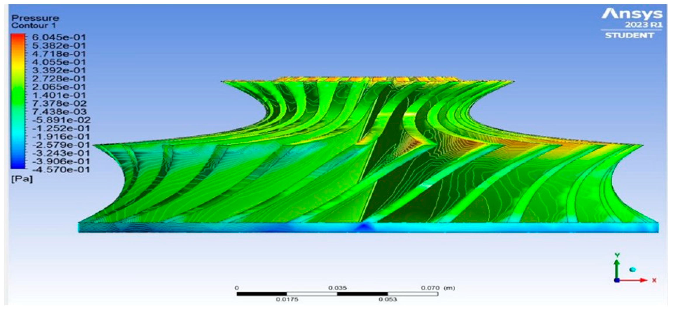
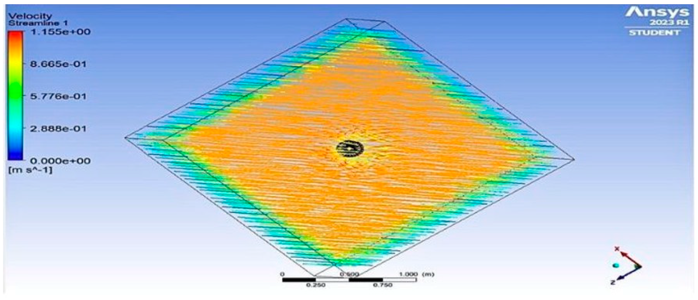
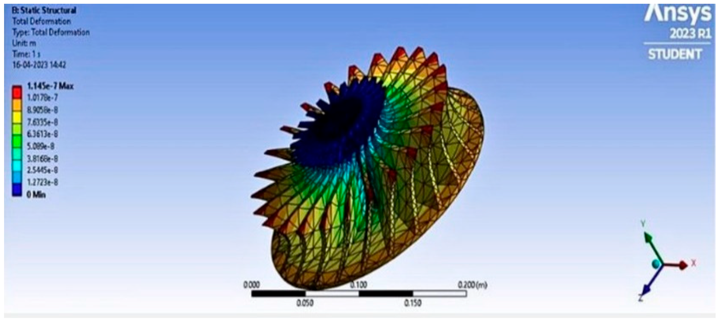
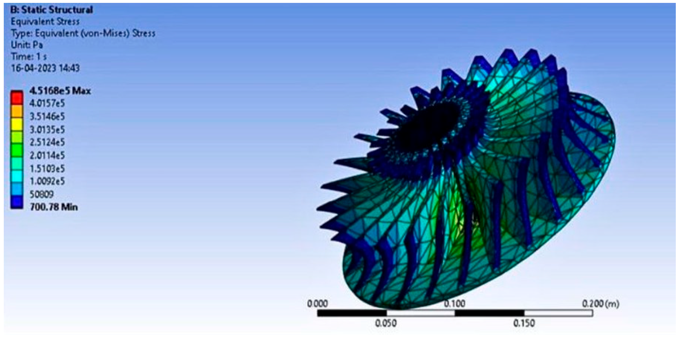
| Alloy | von Mises Stress (Pa) | Deformation (m) | Velocity (m/s) | Pressure (Pa) |
|---|---|---|---|---|
| Al 2618 alloy | 4.5168 × 10⁸ | 1.145 × 10⁻⁷ | 1.132 | 4.718 |
| Ti 6-2-4-6 | 6.7561 × 10⁸ | 1.392 × 10⁻³ | 2.124 | 5.819 |
Disclaimer/Publisher’s Note: The statements, opinions and data contained in all publications are solely those of the individual author(s) and contributor(s) and not of MDPI and/or the editor(s). MDPI and/or the editor(s) disclaim responsibility for any injury to people or property resulting from any ideas, methods, instructions or products referred to in the content. |
© 2024 by the authors. Licensee MDPI, Basel, Switzerland. This article is an open access article distributed under the terms and conditions of the Creative Commons Attribution (CC BY) license (https://creativecommons.org/licenses/by/4.0/).
Share and Cite
Ravinath, G.; Pushpa Latha, P.; Priya, L.; Ramesh, J. Optimizing and Analyzing a Centrifugal Compressor Impeller for 50,000 rpm: Performance Enhancement and Structural Integrity Assessment. Eng. Proc. 2023, 59, 221. https://doi.org/10.3390/engproc2023059221
Ravinath G, Pushpa Latha P, Priya L, Ramesh J. Optimizing and Analyzing a Centrifugal Compressor Impeller for 50,000 rpm: Performance Enhancement and Structural Integrity Assessment. Engineering Proceedings. 2023; 59(1):221. https://doi.org/10.3390/engproc2023059221
Chicago/Turabian StyleRavinath, Gayathri, Ponmary Pushpa Latha, Lakshmi Priya, and Joshna Ramesh. 2023. "Optimizing and Analyzing a Centrifugal Compressor Impeller for 50,000 rpm: Performance Enhancement and Structural Integrity Assessment" Engineering Proceedings 59, no. 1: 221. https://doi.org/10.3390/engproc2023059221