
LS-Dyna Impact Modelling on Carbon Fibre Reinforced Polymers (CFRP) Composite Aircraft Panel with Various Impactors †


Division of Aerospace Engineering, Karunya Institute of Technology and Sciences, Coimbatore 641114, Tamilnadu, India
*
Author to whom correspondence should be addressed.
†
Presented at the International Conference on Recent Advances in Science and Engineering, Dubai, United Arab Emirates, 4–5 October 2023.
Eng. Proc. 2023, 59(1), 26; https://doi.org/10.3390/engproc2023059026
Published: 10 December 2023
(This article belongs to the Proceedings of Eng. Proc., 2023, RAiSE-2023)
Abstract
:In the aviation industry, the usage of composites is increasing because of their unique feature in terms of damage tolerance and high structural integrity. It inspires the researcher to focus on dynamic behaviour of subsonic aircraft hat-shaped CFRP composite panels using the LS-Dyna tool to prove its excellent impact behaviour with the help of spherical, ogival and conical impactors. High-velocity impact simulations conducted in this research work duplicate the Foreign Object Damage on aircraft panels. The impact load locations are identified from the literature and notable damage features such as stresses, delamination length, internal energy absorbed, resultant force, delamination zone, resultant acceleration and resultant velocity are compared for the chosen impactor shapes. The elastic and plastic failure zones are displayed very clearly in the results to avoid any further damage in the future. All results help to understand the composite shell behaviour and different damage patterns.
1. Introduction
The Bombardier LEARJET 70 aircraft that can fly at Mach 0.75 is considered and the CFD and FEA simulation results help us to understand the impact of damage at the upper wing panel [1]. As laminated composites exhibit heterogeneous, anisotropic and brittle behaviour under various impact loads, the impact damage proves notable damage at both low as well as high velocities [2]. The types of impact loading are lower velocities with large masses—10 m/s, intermediate velocities—10 to 50 m/s, high/ballistic velocities with small masses—50 to 1000 m/s and impact hypervelocities—2000 to 5000 m/s. The chosen aircraft falls under the high or ballistic velocity category.
LS-Dyna modelling is done to reproduce the physical properties of preloaded composite panels under low-speed loading [3]. Three energy levels are used to act on wooden panels made of four distinct fibre directions. The resulting differences in damage initiation, progression, and durability reduction of the affected layers are compared [4,5,6,7,8]. The impact properties were studied using a proven longitudinal bar and shell layering process [9,10,11]. Research is being conducted to improve the specific energy absorption capacity (SEA), ballistic limiting speed and total energy absorption capacity of triangular, circular and hexagonal reinforcements against high-speed blunt impacts [12,13,14,15,16,17]. The optimal shape of the soft body impactor and its impact on CFRP laminates are evidence that the deformation is notable and also flows over the structure, spreading the impact load [18].
The effect of impactor shapes under consideration produces well-proven results that are recorded in this research article.
2. Modelling of Composite Panel with Impactor
Solid Modelling
The parametric modelling of the plate and stringer are conducted. The size of skin is 127 × 200 mm. The thickness of the skin and stringer are 2.82 and 3.01 mm, respectively. The size of the stringer is assumed from the literature. The impactor is also modelled based on the available experimental setup. Table 1 represents the properties of the material below.
The 3D Hashin failure criterion is recommended for exploring the failure behaviour of carbon fibre and epoxy matrix under impact load. To understand the failure in fibre and matrix because of tensile loading and compressive loading due to impact, five contour plots are used in this simulation. The plate and impactor are designed as a shell structure. The aircraft velocity is given as the impactor velocity and contact conditions are given to close the gap between the skin and the stringer. Nearly one million triangular elements are obtained. Tie-break contact is used in this research. To measure the delamination length in the perforated region, Chang–Chang impact modelling has been used.
3. Results and Discussion
The damage characteristics of spherical, conical and ogival impactors are discussed with the help of the LS-Dyna tool.
3.1. Spherical Impactor
The FEA results of spherical impactor are displayed below.
Distributions of X-stresses are sketched below.
Figure 1 shows that the max. value of X-stress is 1869 MPa. The zero-failure region is indicated in blue colour. The delamination length is (27 mm, 21 mm).
The variation of Y-stress is displayed below in Figure 2.
The maximum value of Y-stress is 1332 MPa. The Z-stress distribution is shown below in Figure 3.
The maximum value of Z-stress is 1660 MPa and it is observed at impact locations.
The maximum value of stress seems to be near the impact region. It is also observed that the fibres are intact at some distance away from the point of impact. In all three cases, the impactor bounces back but the amount of perforation is much less. The peak velocity and peak acceleration values from ten different points randomly chosen including impact region, top flange, and both sides of the web are 23.44 m/s and 18 × 103 m/s2, respectively. Similarly, the minimum velocity and acceleration values are 0.1 m/s and 0.5 × 10³ m/s2, respectively.
The internal energy absorbed is 117.1 kJ and the drop in kinetic energy is 20 kJ. Hence, the total energy remains constant and its value is 125.7 kJ.
Figure 4, Figure 5, Figure 6, Figure 7 and Figure 8, the Red regions in history variables 1, 2, 3, 4 and 5 indicate a healthy structure that exhibits elastic conditions. History variables 1, 2, 3, 4 and 5 are designed for the following modes: tensile fibres, compressive fibres, tensile matrices, compressive matrices and failures, respectively.
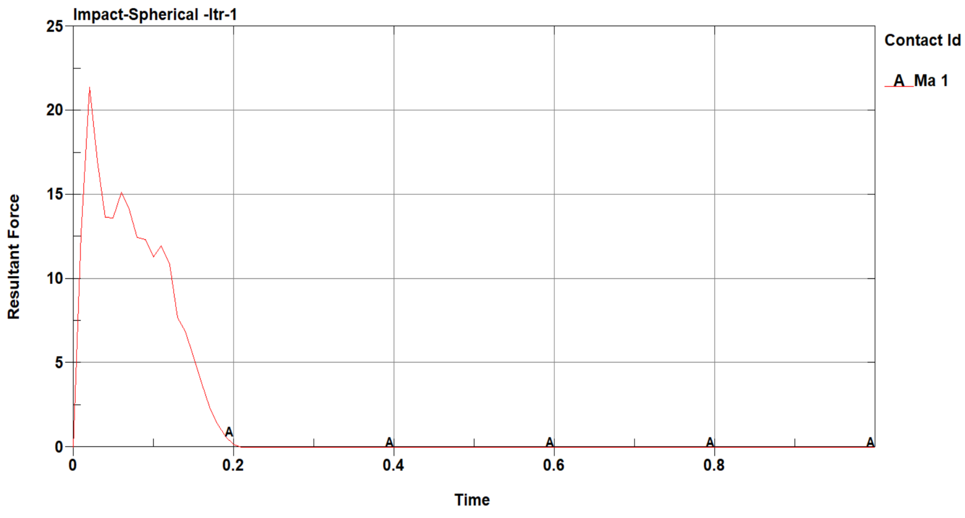
The resultant contact force from the spherical impactor is 21.5 kN.
3.2. Conical Impactor
The maximum value of X-stress is 1734 MPa and it is in the region of impact. The delamination length is (36 mm, 25 mm).
Figure 9, Figure 10 and Figure 11 show that the maximum value of Y-stress is 924.2 MPa and its value is lower than X-stress because of the fibre orientation. Here, the fibre orientation is fixed.
Figure 12 shows that the Z-stress value is 1745 MPa, i.e., the max. value when X and Y-stress values are compared. The peak resultant velocity and the minimum value are 32.92 m/s and 0.2 m/s, respectively. The peak resultant acceleration and the minimum acceleration value are 30 × 103 m/s2 and 0.2 × 10³ m/s2, respectively.
It is noted that internal energy increases and it remains almost the same. At the same time, kinetic energy decreases with time and it rises to some extent, after which there is no notable change. The values of total, kinetic and internal energies are 119.8 kJ, 109.9 kJ and 239.6 kJ, respectively. The fibre tension mode is not subjected to failure but the existence of failure has been proven in the following modes: fibre compression, tension and compression matrices. The overall damage shows elastic behaviour.
Figure 13 shows that the contact force from the conical impactor is 21.5 kN.
3.3. Ogival Impactor
Figure 14 shows that the maximum value of the X-stress is 1551 MPa and it is in the region of impact. The delamination length is (27 mm, 22 mm).
The maximum value of Y-stress is 770.3 MPa and the web of the composite panel shows the existence of fibre breakage, shown in Figure 15.
Figure 16 shows that the maximum value of Z-stress is 1650 MPa and it is in the region of impact.
The peak value of resultant velocity is 25 m/s and the minimum value is 0.1 m/s.
Similarly, the peak value of acceleration is 27.5 × 10³ m/s2 and the minimum value is 0.1 × 10³ m/s2.
The value of kinetic energy is 31.56 kJ and it is transformed to internal energy of 176.3 kJ. The constant total energy is 123.67 kJ.
The fibre tension failure does not occur during the impact [19]. The simulation results clearly display the existence of plastic conditions in fibre compression, matrix tension and matrix compression. The cumulative damage mode shows the elastic condition.
4. Conclusions
The mechanical behaviour of the CFRP panel with hat stringer relies upon the fibre thickness, number of layers and fibre orientation. Based on the literature, the specifications of the CFRP panel were fixed and dynamic analysis using LS-Dyna 4.5 software was carried out to understand the critical area and damage pattern. The features of the 3D Hashin and Chang–Chang methods were used to obtain better simulation results. It is concluded the energy absorption varies with the impactor shape. Numerically, it has been proven that the highest internal energy absorption takes place in the conical impactor. The strain rate also reaches the maximum in conical rather than in ogival impactors. The delamination length was also measured, and the impact characteristics were not the same. The impactor bounces back in some instances, also not returning based on its residual energy. The lowest damage level is observed in the spherical impactor. So, any debris within the spherical nose can create the minimum damage level in the CFRP panel. The resultant velocity and resultant acceleration are high in critical areas. The contour plots help to visualize that the CFRP panel is stronger in the fibre direction in comparison with other directions and it is also in accordance with the available literature and experimental results. The resultant force of 18.5 kN from the ogival impactor is the lowest in comparison with the other two impactors.
Author Contributions
Conceptualization, G.R. and J.J.W.; methodology, G.R.; validation, J.J.W.; formal analysis, G.R. and J.J.W.; data curation, J.J.W.; writing—original draft preparation, J.J.W.; writing—review and editing, G.R.; supervision, J.J.W. All authors have read and agreed to the published version of the manuscript.
Funding
This research received no external funding.
Institutional Review Board Statement
Not applicable.
Data Availability Statement
The data can be obtained from the corresponding author on request.
Acknowledgments
We acknowledge the institutional management and family members for their immense support.
Conflicts of Interest
The authors declare no conflict of interest.
References
- Kowshik, S.; Gowrishankar, M.C.; Shettar, M.; Bhat, R.; Gurumurthy, B.M. Durability prediction analysis on mechanical properties of GFRP upon immersion in water at ambient temperature. Cogent Eng. 2021, 8, 1956869. [Google Scholar] [CrossRef]
- Shettar, M.; Kowshik, S.; Hiremath, P.; Sharma, S. Water sorption-desorption-resorption effects on mechanical properties of epoxy-nanoclay nanocomposites. Int. J. Automot. Mech. 2022, 19, 9478–9486. [Google Scholar] [CrossRef]
- Gayathri, R. Design and characteristics study of an aircraft tapered wing. Int. J. Mech. Eng. 2022, 7, 6985–7000. [Google Scholar]
- Heimbs, S.; Heller, S.; Middendorf, P.; Hähnel, F.; Weiße, J. Low velocity impact on CFRP plates with compressive preload: Test and modelling. Int. J. Impact Eng. 2009, 36, 1182–1193. [Google Scholar] [CrossRef]
- Hou, Y.; Li, C.; Zhou, X.; Sapanathan, T.; Rachik, M. An insight into the low-velocity impact behavior of patch-repaired CFRP laminates using numerical and experimental approaches. Compos. Struct. 2018, 190, 179–188. [Google Scholar]
- Icten, B.M.; Kıral, B.G.; Deniz, M.E. Impactor diameter effect on low velocity impact response of woven glass epoxy composite plates. Compos. B Eng. 2013, 50, 325–332. [Google Scholar] [CrossRef]
- Jims John Wessley, G.; Gaith Franklin, A.; Vijay, S.J. Fabrication and Mechanical Characterization of Stir CastAA6063-Borosilicate-Fly Ash Hybrid Metal Matrix Composites. Int. J. Eng. Technol. 2018, 7, 101–105. [Google Scholar] [CrossRef]
- Mo, G.L.; Ma, Q.W.; Jin, Y.X.; Li, Z.X.; Wu, Z.L. Delamination process in cross-ply UHMWPE laminates under ballistic Penetration. Def. Technol. 2021, 17, 278–286. [Google Scholar] [CrossRef]
- Mo, Y.; Ge, D.; He, B. Experiment and optimization of the hat-stringer-stiffened composite panels under axial Compression. Compos. B. Eng. 2016, 84, 285–293. [Google Scholar] [CrossRef]
- Nishikawa, M.; Hemmi, K.; Park, S.; Nadabe, T.; Takeda, N. Finite Element Analysis on the Impact-Induced Damage of Composite Fan Blades Subjected to a Bird Strike. Trans. Jpn. Soc. Aeronaut. Space Sci. 2010, 58, 261–268. [Google Scholar] [CrossRef]
- Rajamanickam, R. Study of Delamination of Composite Hat Skin Stringer Interface Failure. Master’s Thesis, Blekinge Institute of Technology, Karlskrona, Sweden, 2019. [Google Scholar]
- Rakesh, P.K.; Sharma, V.; Singh, I.; Kumar, D. Delamination in Fiber Reinforced Plastics: A Finite Element Approach. Engineering 2011, 03, 549–554. [Google Scholar] [CrossRef]
- Ambri, A.; Kaur, R. Spars and Stringers-Function and Designing Ambri Student (Aerospace). Int. J. Aerosp. Eng. 2014, 1, 58–61. [Google Scholar]
- Winkel, J.D.; Adams, D.F. Instrumented drop weight impact testing of cross-ply and fabric composites. Compos 1985, 16, 268–278. [Google Scholar] [CrossRef]
- Xu, W.; Liu, L.; Xu, W. Experiments and Finite Element Simulations of Composite La9minates Following Low Velocity On-Edge Impact Damage. Polymers 2022, 14, 1744. [Google Scholar] [CrossRef]
- Zhou, J.; Liao, B.; Shi, Y.; Zuo, Y.; Tuo, H.; Jia, L. Low-velocity impact behavior and residual tensile strength of CFRP laminates. Compos. B Eng. 2019, 161, 300–313. [Google Scholar] [CrossRef]
- Gonzalez-Jimenez, A.; Manes, A.; Beligni, A.; Dziendzikowski, M.; Sbarufatti, C.; Giglio, M. Modelling and experimental testing of thick CFRP composites subjected to low velocity impacts. Procedia Struct. Integr. 2019, 24, 101–109. [Google Scholar] [CrossRef]
- Sommer, D.E.; Thomson, D.; Falcó, O.; Quino, G.; Cui, H.; Petrinic, N. Damage modelling of carbon fibre composite crush tubes: Numerical simulation and experimental validation of drop weight impact. Compos. Part A Appl. Sci. Manuf. 2022, 160, 107033. [Google Scholar] [CrossRef]
- Colamartino, I.; Bassi, S.M.; Benetton, D.; Anghileri, M. A Semi-Empirical Damage Evaluation Criterion for Thin Composite Impact Analysis. J. Dyn. Behav. Mater. 2022, 8, 424–436. [Google Scholar] [CrossRef]
- Falzon, B.G. Computational modelling of the crushing of carbon fibre-reinforced polymer composites. Philos. Trans. R. Soc. A 2022, 380, 20210336. [Google Scholar] [CrossRef]
Figure 1.
X-stress of spherical impactor.
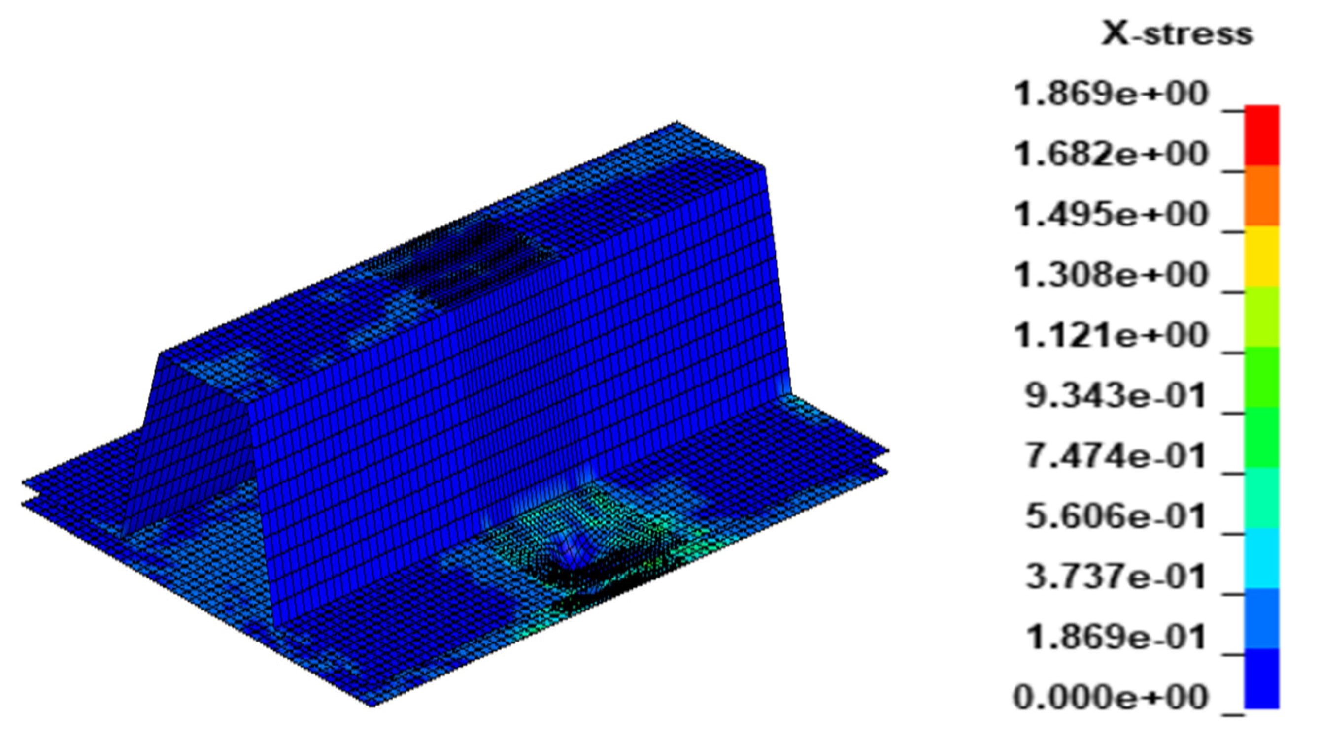
Figure 2.
Y-stress of spherical impactor.

Figure 3.
Z-stress of spherical impactor.
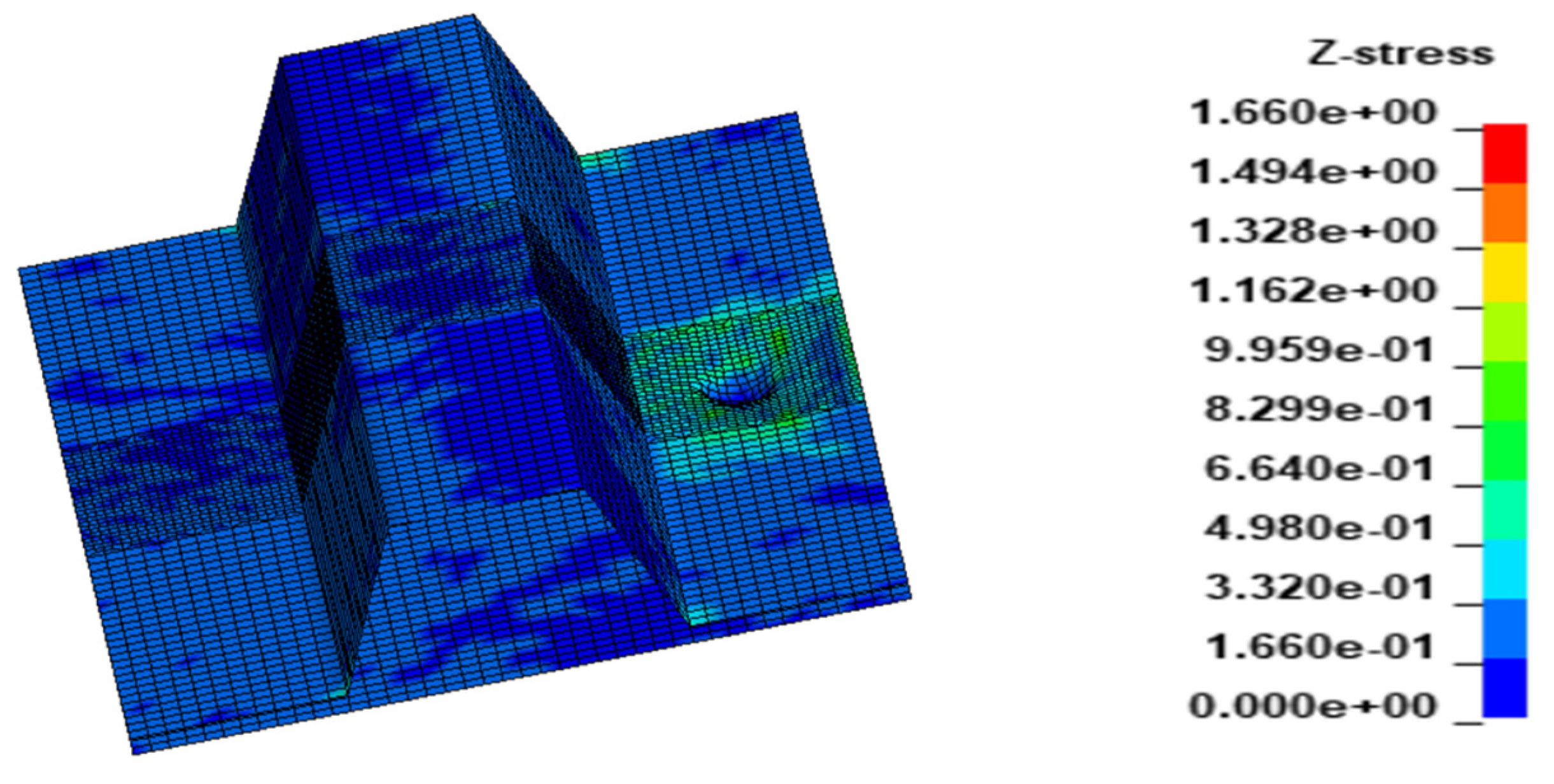
Figure 4.
Contours of history variable 1 (fibre tension mode).
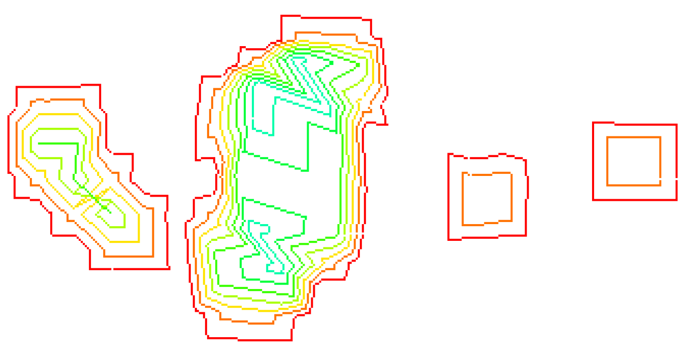
Figure 5.
Contours of history variable 2 (fibre compression mode).

Figure 6.
Contours of history variable 3 (matrix tension mode).

Figure 7.
Contours of history variable 4 (matrix compression mode).
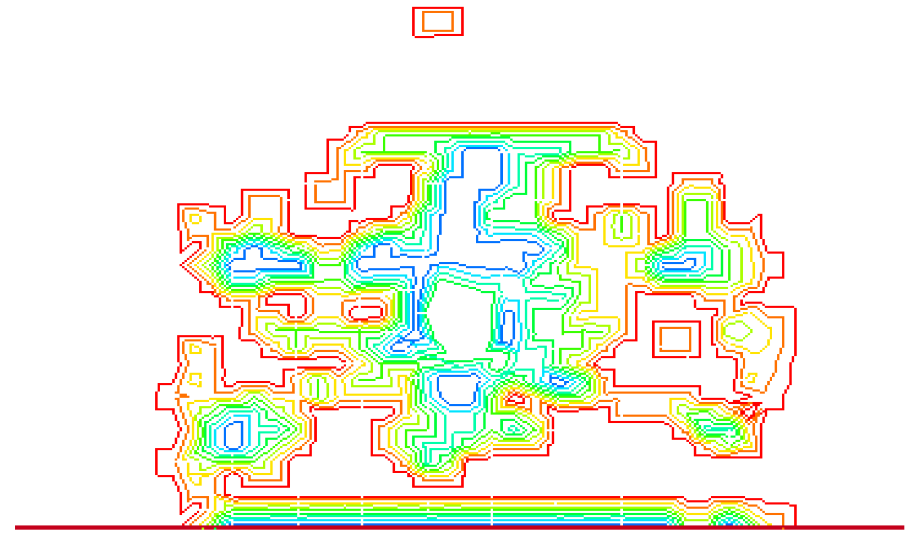
Figure 8.
Contours of history variable 5 (cumulative condition).
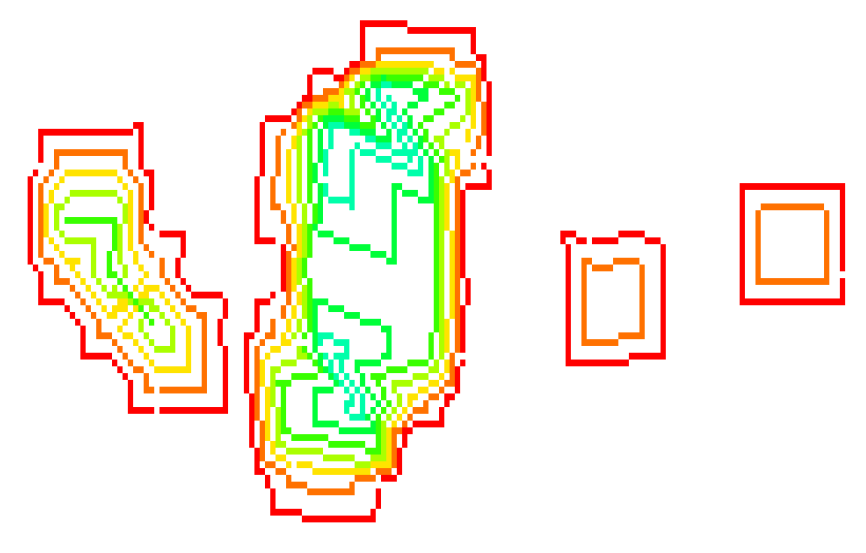
Figure 9.
Resultant force.

Figure 10.
X-stress of conical impactor.

Figure 11.
Y-stress of conical impactor.
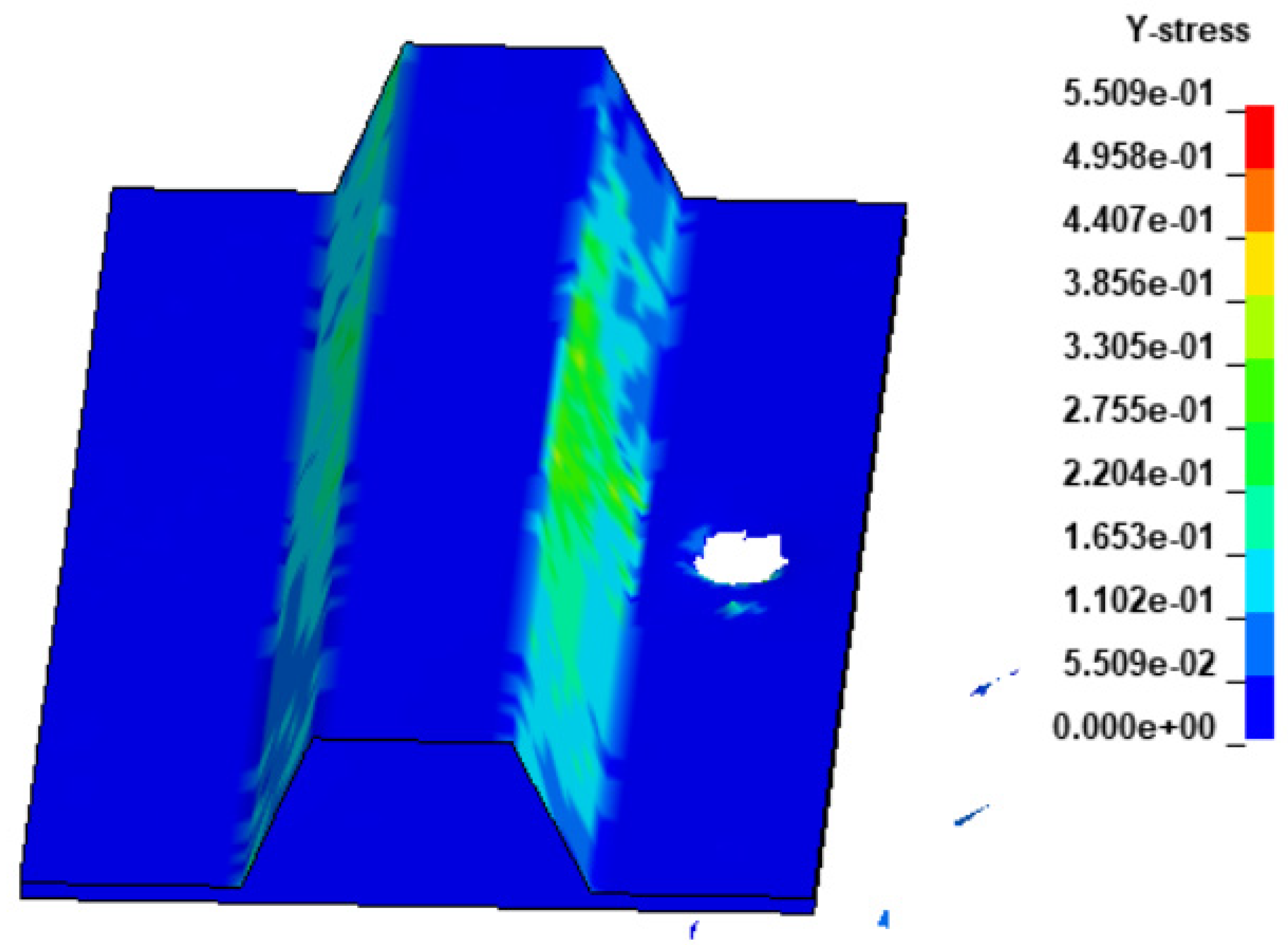
Figure 12.
Z-stress of conical impactor.
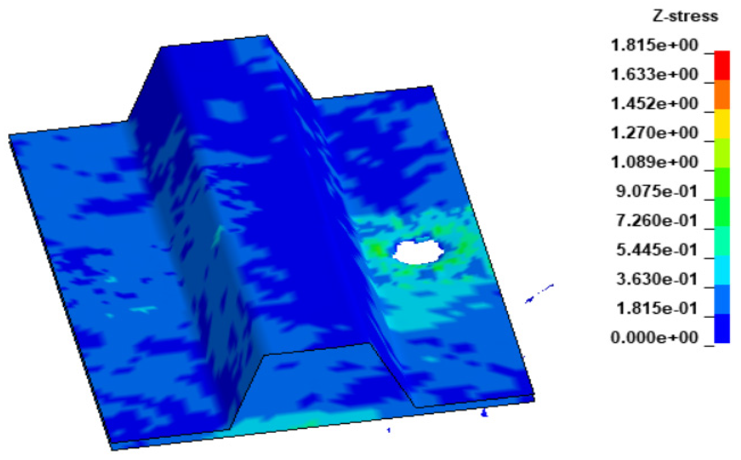
Figure 13.
Contact force.
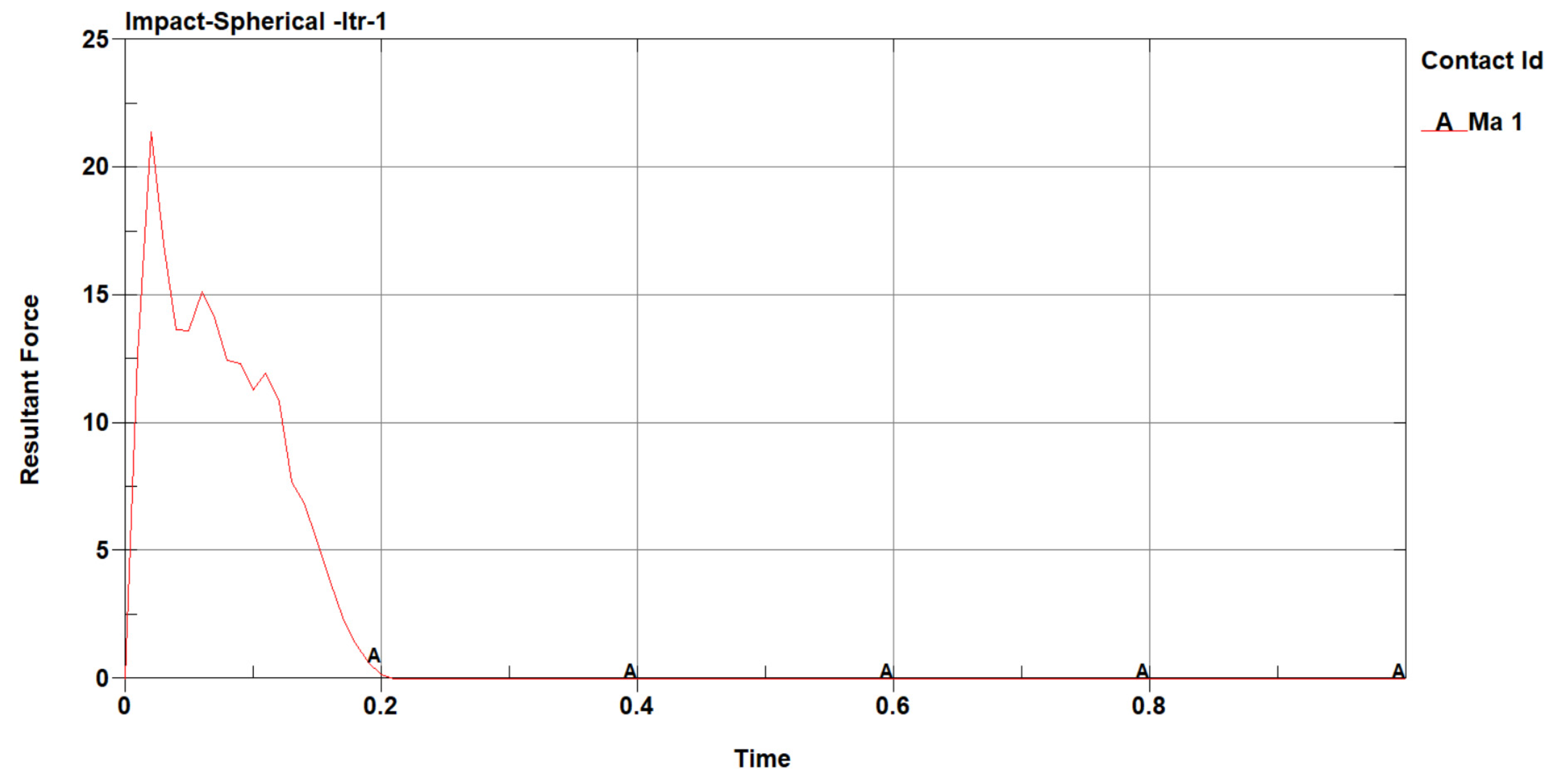
Figure 14.
X-stress of ogival impactor.

Figure 15.
Y-stress of ogival impactor.
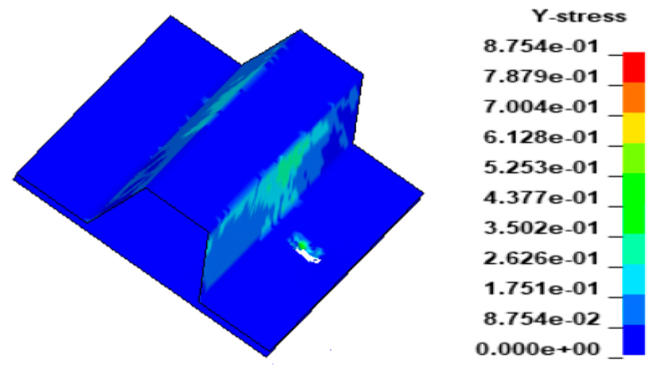
Figure 16.
Z-stress of ogival impactor.
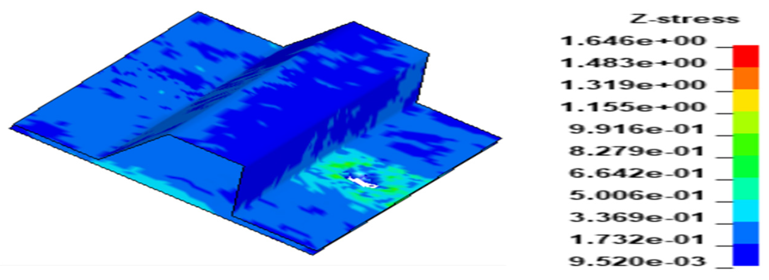
Figure 17.
Contact force.

Table 1.
Parametric modelling of plate and stringer.
| Mechanical Property | Value |
|---|---|
| Young’s moduli (Longitudinal), E11 | 153 GPa |
| Young’s moduli (Transverse), E22 (E22 = E33) | 10.3 GPa |
| Shear moduli (In-plane), G12 | 5.2 GPa |
| Poisson’s ratios (Major), ʋ12 | 0.3 |
| Tensile strengths (Longitudinal), XT | 2540 MPa |
| Compressive strengths (Longitudinal), XC | 1500 MPa |
| Tensile strengths (Transverse), YT | 82 MPa |
| Compressive strengths (Transverse), YC | 236 MPa |
| Shear strengths, SC | 90 MPa |
| Failures in tension, DFAILT | 0.017 |
| Failures in compressions, DFAILC | 0.0135 |
| Matrix strains, DFAILM | 0.1 |
| Failures in shears, DFAILS | 0.03 |
| Modes I energy release rates, GIC | 225 J/m2 |
| Modes II energy release rates, GIIC | 640 J/m2 |
Disclaimer/Publisher’s Note: The statements, opinions and data contained in all publications are solely those of the individual author(s) and contributor(s) and not of MDPI and/or the editor(s). MDPI and/or the editor(s) disclaim responsibility for any injury to people or property resulting from any ideas, methods, instructions or products referred to in the content. |
© 2023 by the authors. Licensee MDPI, Basel, Switzerland. This article is an open access article distributed under the terms and conditions of the Creative Commons Attribution (CC BY) license (https://creativecommons.org/licenses/by/4.0/).
Share and Cite
MDPI and ACS Style
Ravinath, G.; Wessley, J.J. LS-Dyna Impact Modelling on Carbon Fibre Reinforced Polymers (CFRP) Composite Aircraft Panel with Various Impactors. Eng. Proc. 2023, 59, 26. https://doi.org/10.3390/engproc2023059026
AMA Style
Ravinath G, Wessley JJ. LS-Dyna Impact Modelling on Carbon Fibre Reinforced Polymers (CFRP) Composite Aircraft Panel with Various Impactors. Engineering Proceedings. 2023; 59(1):26. https://doi.org/10.3390/engproc2023059026
Chicago/Turabian StyleRavinath, Gayathri, and Jims John Wessley. 2023. "LS-Dyna Impact Modelling on Carbon Fibre Reinforced Polymers (CFRP) Composite Aircraft Panel with Various Impactors" Engineering Proceedings 59, no. 1: 26. https://doi.org/10.3390/engproc2023059026