Proceeding Paper

The Effect of Process Parameters on Quality Characteristics in the Drilling of Aluminium–Metal Matrix Composites †

1
Department of Mechanical Engineering, Vidyavardhaka College of Engineering, Mysuru 570002, Karnataka, India
2
Department of Chemistry, Vidyavardhaka College of Engineering, Mysuru 570002, Karnataka, India
*
Author to whom correspondence should be addressed.
Presented at the International Conference on Recent Advances on Science and Engineering, Dubai, United Arab Emirates, 4–5 October 2023.
Eng. Proc. 2023, 59(1), 53; https://doi.org/10.3390/engproc2023059053
Published: 15 December 2023
(This article belongs to the Proceedings of Eng. Proc., 2023, RAiSE-2023)

Abstract

:
Present work focusses on investigating the effect of process parameters such as feed rate and spindle speed on quality characteristics of the hole, i.e., surface roughness (Ra) and circularity at entry and exit in the drilling of aluminium (Al) 6061 reinforced with different volume fraction of silicon nitride (Si3N4). Optimum parameters for Ra and circularity of hole at entry and exit are obtained as feed rate at 0.125 mm/rev, spindle speed at 300 rpm, diameter of drill at 8 mm, and % Vol. of Si3N4 at 5%. Using Analysis of Variance (ANOVA), we observed that spindle speed is the most influential parameter followed by feed rate.

1. Introduction

Al 6061 is largely employed in heavy-duty structural components of automobile, aerospace and defense systems because of its good strength-to-weight ratio. Mechanical properties of Al 6061 such as tensile strength, microhardness, ballistic resistance, etc., can be enhanced by reinforcing with ceramic materials such as metal oxides, nitrides and carbides [1,2]. Si3N4 is a metal nitride that provides excellent creep properties and tensile strength with a reduction in ductility when it is reinforced in appropriate proportion with Al 6061 endowed this combination for structural applications [3,4]. Previous studies have shown that Al 6061 reinforced with Si3N4 enhances corrosion resistance, wear resistance and metallurgical stability at high temperatures making this composite suitable for high wear and thermal-resistant applications [5]. Stir casting is the liquid state fabrication technique found to be a reliable production method for Al-Si3N4 MMC offers good mechanical and tribological properties [3,4,5,6,7]. Stir casting produces outstanding characteristics in Al-Si3N4 with regulated process conditions, and its low material density of 3.3 g/cm3 and heat conductivity of 170–230 W/mk make it excellent for applications where weight is an issue [3,8]. The presence of agglomerated reinforcing components in the matrix causes a non-uniform metallurgical structure, which leads to poor machinability of Al-MMCs during drilling operations, resulting in a shorter tool life, poor surface integrity, higher energy consumption, increased cutting force and so on [9]. Due to the poor quality of the hole created during drilling, mechanical assemblies are susceptible to failure over time. Selection of the correct volume proportion of Si3N4 in the Al matrix phase plays an important role in improving the machinability of the Al-Si3N4 composite. Levels of process parameters significantly affect the machining zone temperature while drilling the workpiece [10]. Only a few researchers have carried out an investigation on the effect of the volume proportion of Si3N4 in Al MMCs on the quality of drilling operations. Surface roughness, circularity and cylindricity are greatly influenced by the volume proportion of Si3N4 [11]. Drilling process parameters such as spindle speed and feed rate are the most obvious influence on the quality of the hole. Spindle speed, then feed, has the greatest effect on the thrust force [12]. Cutting velocity has the second-greatest impact on the surface after feed rate [13]. But, none of the work has suggested the standardized process parameters in the drilling of Al-MMC, in particular Al-Si3N4 composites. It becomes necessary to study the significant effect of process parameters on the quality characteristics of a hole before announcing them as standard parameters. Taguchi method is the easiest and most deliberate statistical approach to evaluate the effect of cutting parameters on output variables [14,15]. An analytical statistical technique known as ANOVA is used to quantify the relative importance of each factor on the objective function [11,16]. The relative contribution of each control factor to the output response is effectively determined through ANOVA so that it helps in obtaining the optimized parameter for the desired output [17,18]. Hence, the current study aims to investigate the effect of cutting parameters such as feed rate and spindle speed at various levels on the surface roughness and circularity of the hole in the drilling of Al 6061 reinforced with different volume proportions of Si3N4 MMC, fabricated using stir casting method.

2. Materials and Methods/Methodology

2.1. Material

In the present study, Al 6061 is selected as matrix material and α-phase Si3N4 as reinforcement. The properties of Al 6061 and Si3N4 are mentioned in Table 1.

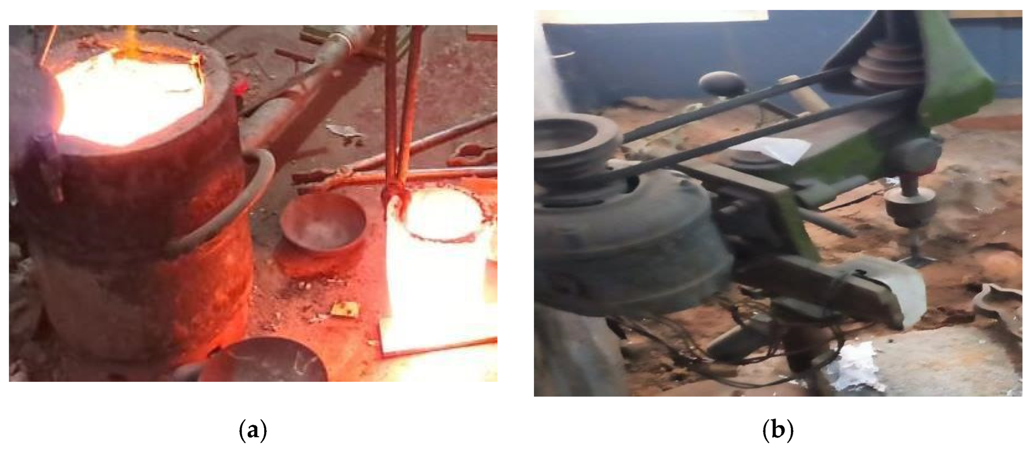
2.2. Stir Casting Process
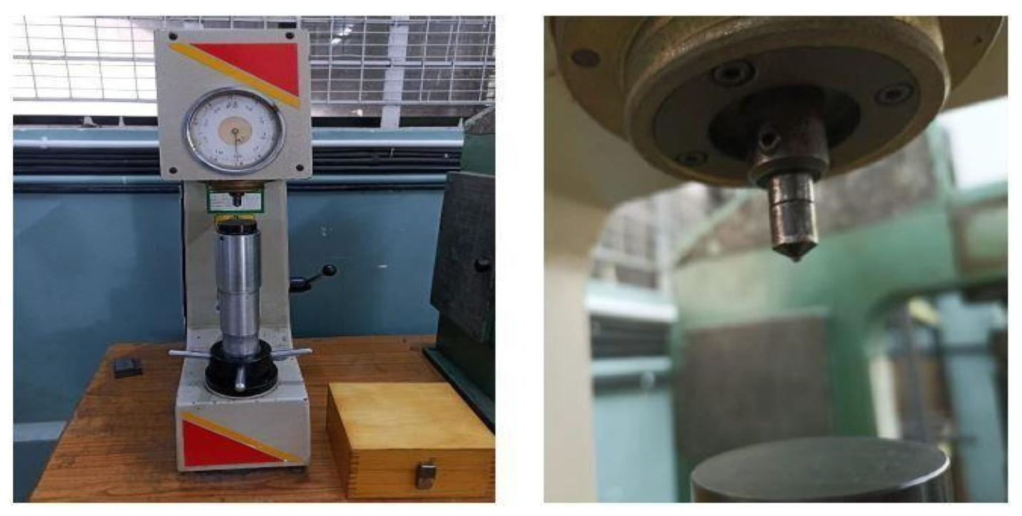
The stir casting process is the most economical and simple method to fabricate MMCs [18,19,20]. Al 6061 is reinforced with Si3N4 in three different volume proportions (i.e., 0%, 5% and 10%). Three different composite specimens are prepared to the size of the mould 52 mm × 51 mm × 20 mm using the stir casting process as shown in Figure 1a,b. The compositions of the specimens are mentioned in Table 2.

2.3. Hardness Test

The hardness of the composites is measured using a Rockwell hardness tester, as shown in Figure 2.

2.4. Planning of Experiments

Experiments are planned using Taguchi’s technique in Minitab software 18.1. Four control factors of three levels are selected for the study; details of the control factors and their levels are mentioned in Table 3. Taguchi’s L27 standard orthogonal array is selected for 4 control factors at 3 levels to conduct the experiment.

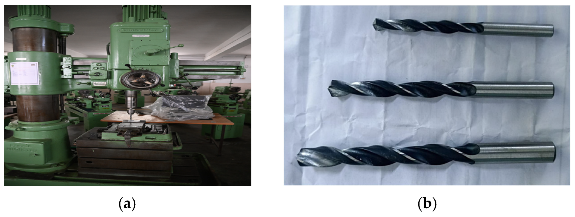
2.5. Drilling of Al-Si3N4 Composite Specimens

Al 6061 MMC reinforced with 0%, 5% and 10% volume proportion of Si3N4. Drilling is performed on the composite workpieces using special purpose automatic radial drilling machine as shown in Figure 3a. The cutting parameters are set based on Taguchi’s L27 standard orthogonal array. HSS drill bits of 6 mm, 8 mm and 10 mm diameter are used for the drilling process as shown in Figure 3b.

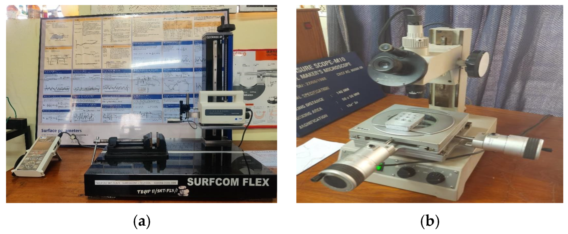
2.6. Surface Roughness and Circularity Measurement

The surface roughness of each hole is measured using Surfcom Flex with a sampling length of 4 mm, as shown in Figure 4a. Circularity at entry and exit of the hole is measured using a Tool Maker’s Microscope with the lowest count of 0.001 mm as shown in Figure 4b. The diameter of the hole is measured both along the X and Y axes and measurements are used to calculate the circularity of the hole based on the two-point method using Equation (1).
C i r c u l a r i t y = M a x D i a   X , D i a   Y M i n ( D i a   X , D i a   Y ) 2

3. Results

3.1. Hardness

The measured hardness of the composite workpieces is tabulated as shown in Table 3.

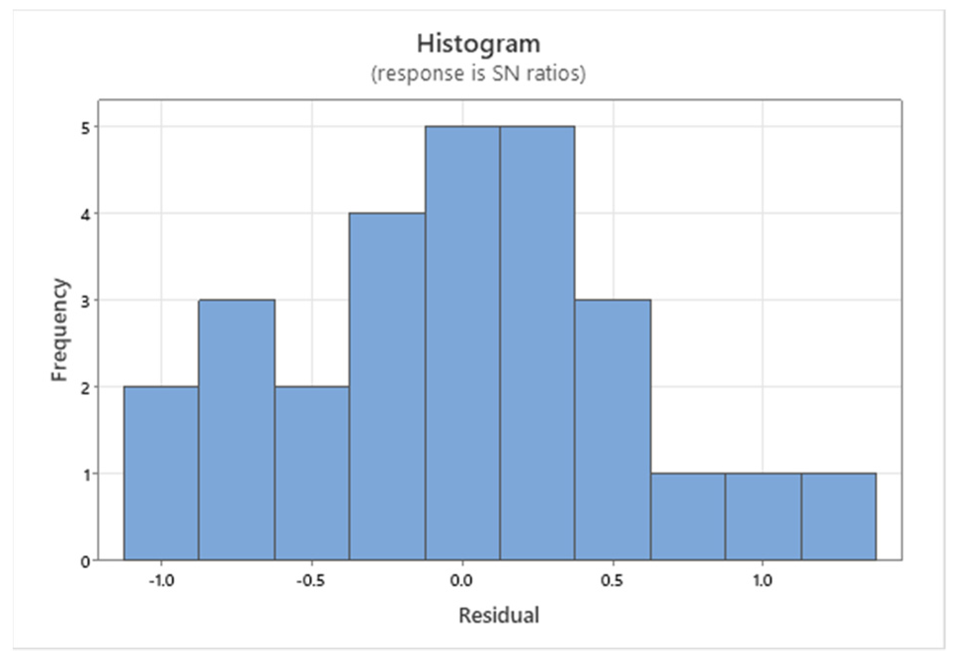
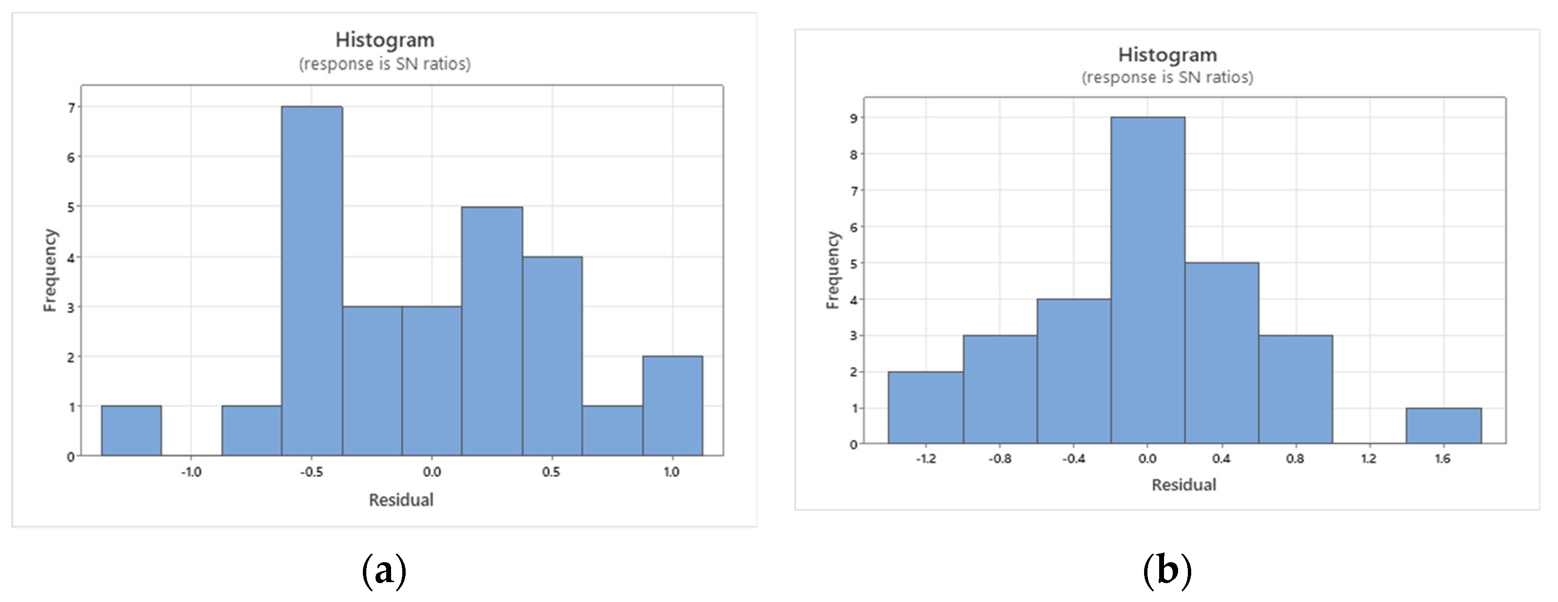
3.2. Taguchi Analysis

Taguchi’s statistical approach gives the way to know the effect of control factors under consideration on the Ra and circularity of drilled holes [21]. Experimental runs according to Taguchi’s L27 orthogonal array and results such as surface roughness (Ra) and circularity at entry and exit of the hole are tabulated as shown in Table 4. Holes created on the workpieces by drilling are shown in Figure 5.
The influence of control factors on the responses is investigated using Taguchi’s technique, where experimental results of each run are transformed into S/N ratio values. The smaller of the better condition is employed in the analysis of S/N ratios of all the responses. The response table for S/N ratios for Ra is mentioned in Table 5. The response table for S/N ratios for circularity at the entry and exit of holes is mentioned in Table 6 and Table 7, respectively.

3.3. ANOVA

The significant contribution of feed rate, spindle speed, % Vol. of S3N4 and diameter of drill bit on Ra and circularity of the hole at entry and exit is determined by ANOVA. ANOVA for S/N ratios and the effect of process parameters on the responses are shown in Table 8.

4. Discussions

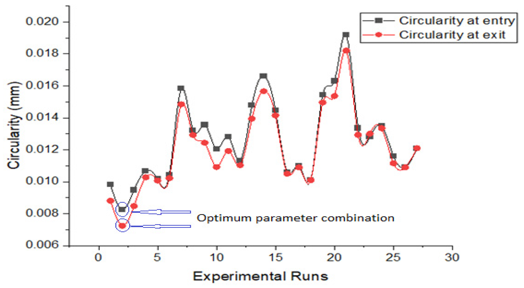
4.1. Effect of Spindle Speed and Feed Rate on Ra and Circularity

From the experiment, it is clearly evident that the Ra value significantly increases as the spindle speed increases from 300 rpm to 1160 rpm. The average Ra value increases from 6.853 μ to 7.775 μ with an increase in feed rate from 300 mm/rev to 580 mm/rev, and further decreases to 7.75 μ with an increase in feed rate from 580 mm/rev to 1160 mm/rev. variation of Ra with spindle speed and feed rate is shown in Figure 6a. The combined effect of feed rate and spindle speed on Ra is shown in Figure 6b. It is evident from Figure 6a that better Ra is obtained at lower feed (0.125 mm) and speed (300 rpm). The circularity of the hole at entry and exit deteriorates as the spindle speed increases from 300 rpm to 580 rpm and further deteriorates more at 1160 rpm. Circularity is significantly affected by spindle speed as compared to feed rate. The circularity of the hole at entry and exit worsens as the feed rate increases from 0.125 mm/rev to 0.575 mm/rev., and further deteriorates as the feed rate increases from 0.575 mm/rev to 1.25 mm/rev. Circularity at exit is better than at entry of the hole due to excessive thrust force. The variation of circularity at the entry and exit of the hole with spindle speed and feed rate is shown in Figure 7.

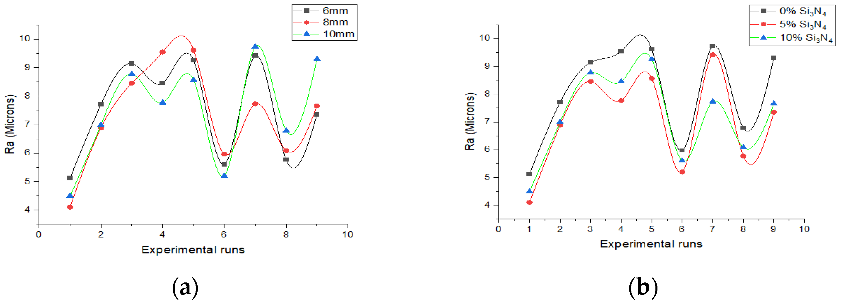
4.2. Effect of Diameter of Drill Bit and % Vol. of Si3N4 Reinforcement on Ra

The effect of the diameter of the drill bit on Ra is shown in Figure 8a. The diameter of the drill bit has no significant effect on Ra, and a superior Ra is attained at 8 mm dia. Ra of the hole surface improves with Si3N4 reinforcement up to 5% and deteriorates further with Si3N4 reinforcement up to 10%. The effect of Si3N4 reinforcement on Ra is shown in Figure 8b.

4.3. ANOVA

Table 3 shows that hardness increases with an increase in % vol. of Si3N4 reinforcement in Al-Si3N4 MMC and maximum hardness of 48.4 RHN is obtained at 10% vol. of Si3N4. The main effects for Ra and circularity at entry and exit are plotted in Figure 9 and Figure 10a,b. Figure 9 shows the effect of process parameters on Ra. It reveals that optimum parameters for Ra are obtained as feed rate at level 1 (0.125 mm/rev), spindle speed at level 1 (300 rpm), the diameter of drill at level 2 (8 mm) and % Vol. of Si3N4 at level 2 (5%). Figure 10a shows the effect of process parameters on the circularity of the hole at entry. Figure 10b shows the effect of process parameters on the circularity of the hole at the exit. It reveals that optimum parameters for circularity of the hole at entry and exit and are obtained as feed rate at level 1 (0.125 mm/rev), spindle speed at level 1 (300 rpm), the diameter of drill at level 2 (8 mm) and % Vol. of Si3N4 at level 2 (5%).
The ANOVA results in Table 8 reveal the significant contribution of each parameter on Ra. Spindle speed has more effect on Ra with its contribution of 56. 57%. The histogram for Ra is plotted in Figure 11. ANOVA for S/N ratios in Table 8 shows the relative contribution of process parameters on circularity at both the entry and exit of the hole, respectively. Spindle speed has more effect on circularity with its contribution of 63.579% at entry and 55.39% at the exit of the hole. The histogram for circularity at the entry and exit of the hole is plotted in Figure 12a,b, respectively. Confirmation experiments are carried out for the optimum combination of process parameters and are in good agreement with the responses with an error of 1%.

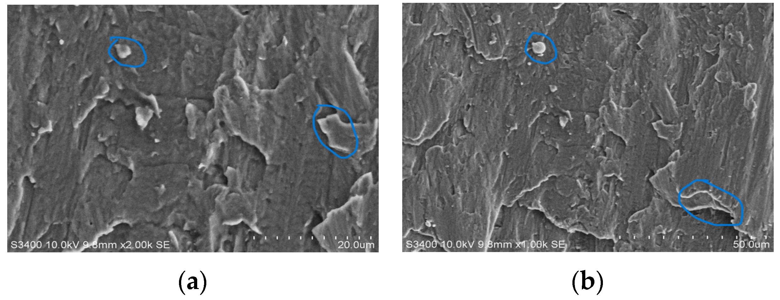
4.4. Microscopic Study of Drilled Hole

Figure 13a,b show a scanning electron microscopy (SEM) image of the drilled hole with optimum parameters. Figure 13a,b shows the aggregation of Si3N4 and matrix burn, which result in roughness on the surface of the drilled hole.

5. Conclusions

This paper presents the effect of process parameters, such as feed rate and spindle speed on quality characteristics of the hole such as surface roughness (Ra), and circularity at entry and exit in the drilling of Al6061, MMC reinforced with Si3N4 at three different volume proportions (0%, 5% and 10%), fabricated using the stir casting technique. Conclusions drawn from the results and discussions are as follows:
  • Optimum parameters for Ra, circularity of hole at entry and exit are obtained as feed rate at level 1 (0.125 mm/rev), spindle speed at level 1 (300 rpm), diameter of drill at level 2 (8 mm), and % Vol. of Si3N4 at level 2 (5%);
  • From ANOVA results, it is concluded that spindle speed is the most influential parameter on Ra and circularity of hole at entry and exit followed by feed rate.

Author Contributions

Conceptualization, K.B.V. and D.S.R.G.; methodology, G.V.N.P.; software, B.S.N.; validation, K.B.V., D.S.R.G. and K.R.; formal analysis, K.R.; investigation, D.S.R.G.; resources, S.; data curation, K.R.; writing—K.B.V. and D.S.R.G.; writing—review and editing, G.V.N.P.; visualization, S.; supervision, K.B.V.; project administration, G.V.N.P.; funding acquisition, G.V.N.P. and K.B.V. All authors have read and agreed to the published version of the manuscript.

Funding

This research was funded by AICTE under the RPS scheme (File No. 8-56/FDC/RPS/POLICY-1/2021-22) with AQIS ID: 1-9290875241.

Data Availability Statement

Data are unavailable due to privacy.

Conflicts of Interest

The authors declare no conflict of interest.

References

  1. Karabulut, Ş.; Karakoç, H.; Bilgin, M.; Canpolat, H.; Krolczyk, G.M.; Sarıkaya, M. A comparative study on mechanical and ballistic performance of functionally graded Al6061 composites reinforced with B4C, SiC, and Al2O3. J. Mater. Res. Technol. 2023, 23, 5050–5065. [Google Scholar] [CrossRef]
  2. Gill, R.S.; Samra, P.S.; Kumar, A. Effect of different types of reinforcement on tribological properties of aluminium metal matrix composites (MMCs)—A review of recent studies. Mater. Today Proc. 2022, 56, 3094–3101. [Google Scholar] [CrossRef]
  3. Sharma, P.; Sharma, S.; Khanduja, D. Production and some properties of Si3N4 reinforced aluminium alloy composites. J. Asian Ceram. Soc. 2015, 3, 352–359. [Google Scholar] [CrossRef]
  4. Rao, P.R.; Mohan, C.B. Study on mechanical performance of silicon nitride reinforced aluminium metal matrix composites. Mater. Today Proc. 2020, 33, 5534–5538. [Google Scholar]
  5. Arya, R.K.; Telang, A. Silicon Nitride as a Reinforcement for Aluminium Metal Matrix Composites to Enhance Microstructural, Mechanical and Tribological Behavior. Int. J. Eng. Adv. Technol. (IJEAT) 2020, 9, 2249–8958. [Google Scholar] [CrossRef]
  6. Lade, J.; Mohammed, K.A.; Singh, D.; Verma, R.P.; Math, P.; Saraswat, M.; Gupta, L.R. A critical review of fabrication routes and their effects on mechanical properties of AMMCs. Mater. Today Proc. 2023, in press. [CrossRef]
  7. Ramesh, C.S.; Keshavamurthy, R.; Channabasappa, B.H.; Pramod, S. Friction and wear behavior of Ni-P coated Si3N4 reinforced Al6061 composites. Tribol. Int. 2010, 43, 623–634. [Google Scholar] [CrossRef]
  8. Gowda, B.U.; Ravindra, H.V.; Gurupavan, H.R.; Ugrasen, G.; Prakash, G.N. Optimization of process parameters in drilling Al-Si3N4 metal matrix composites material using Taguchi technique. Procedia Mater. Sci. 2014, 5, 2207–2214. [Google Scholar] [CrossRef]
  9. Chakraborty, S.; Raut, R.D.; Rofin, T.M.; Chakraborty, S. Optimization of drilling processes of aluminium metal matrix composites using the robust ordinal priority approach. Decis. Anal. J. 2023, 7, 100258. [Google Scholar] [CrossRef]
  10. Samy, G.S.; Kumaran, S.T. Measurement and analysis of temperature, thrust force and surface roughness in drilling of AA (6351)-B4C composite. Measurement 2017, 103, 1–9. [Google Scholar] [CrossRef]
  11. Gowda, B.U.; Ravindra, H.V.; Prakash, G.N.; Nishanth, P.; Ugrasen, G. Optimization of process parameters in drilling of epoxy Si3N4 composite material. Mater. Today Proc. 2015, 2, 2852–2861. [Google Scholar] [CrossRef]
  12. Juliyana, S.J.; Prakash, J.U. Drilling parameter optimization of metal matrix composites (LM5/ZrO2) using Taguchi Technique. Mater. Today Proc. 2020, 33, 3046–3050. [Google Scholar] [CrossRef]
  13. Davim, J.P. Study of drilling metal-matrix composites based on the Taguchi techniques. J. Mater. Process. Technol. 2003, 132, 250–254. [Google Scholar] [CrossRef]
  14. Ravindranath, V.M.; Shankar, G.S.; Basavarajappa, S.; Suresh, R. Optimization of Al/B4C and Al/B4C/Gr MMC Drilling Using Taguchi Approach. Mater. Today Proc. 2017, 4, 11181–11187. [Google Scholar] [CrossRef]
  15. Lingamurthy, K.; Manjunatha, T.H.; Joshi, R.; Basavaraja, Y.; Anilkumar, H.M. Drilling Parameters Optimization and Characterization of Al7075 Reinforced with Al2O3. Mater. Today Proc. 2018, 5, 25092–25101. [Google Scholar] [CrossRef]
  16. Salur, E.; Aslan, A.; Kuntoglu, M.; Gunes, A.; Sahin, O.S. Experimental study and analysis of machinability characteristics of metal matrix composites during drilling. Compos. Part B Eng. 2019, 166, 401–413. [Google Scholar] [CrossRef]
  17. Vankanti, V.K.; Ganta, V. Optimization of process parameters in drilling of GFRP composite using Taguchi method. J. Mater. Res. Technol. 2014, 3, 35–41. [Google Scholar] [CrossRef]
  18. Chakrapani, P.; Suryakumari, T.S.A. Modelling and analysing the water jet machining parameters of aluminium nano composite by ANOVA and Taguchi. Mater. Today Proc. 2021, 47, 370–375. [Google Scholar] [CrossRef]
  19. Samal, P.; Vundavilli, P.R.; Meher, A.; Mahapatra, M.M. Recent progress in aluminum metal matrix composites: A review on processing, mechanical and wear properties. J. Manuf. Process. 2020, 59, 131–152. [Google Scholar] [CrossRef]
  20. Sharma, S.; Bharadwaj, P.; Oza, A.D.; Pandey, A. Application of metal matrix composite fabricated by reinforcement materials—A review. Mater. Today Proc. 2023, in press. [CrossRef]
  21. Saravanan, K.G.; Prabu, R.; Maniraj, S. Parametric optimization of chrome composite through ultrasonic machining using taguchi approach. Mater. Today Proc. 2021, 45, 1975–1978. [Google Scholar] [CrossRef]
Figure 1. (a) Graphite crucible; (b) automatic stirrer in stir casting process.
Engproc 59 00053 g001
Figure 2. Rockwell hardness tester.
Engproc 59 00053 g002
Figure 3. (a) Experimental setup for drilling of Al-MMCs; (b) HSS drill bits.
Engproc 59 00053 g003
Figure 4. (a) Surfcom flex roughness tester. (b) Tool maker’s microscope.
Engproc 59 00053 g004
Figure 5. Drilling operations performed on the workpieces.
Engproc 59 00053 g005
Figure 6. (a) Combined effect of feed rate and spindle speed on Ra; (b) variation of Ra with spindle speed and feed rate.
Engproc 59 00053 g006
Figure 7. The variation of circularity at entry and exit of hole with spindle speed and feed rate.
Engproc 59 00053 g007
Figure 8. (a) Effect of diameter of drill bit on Ra; (b) effect of Si3N4 reinforcement on Ra.
Engproc 59 00053 g008
Figure 9. Main effect plot for S/N ratios (Ra).
Engproc 59 00053 g009
Figure 10. (a) Main effect plot for S/N ratios (circularity at exit); (b) main effect plot for S/N ratios (circularity at entry).
Engproc 59 00053 g010
Figure 11. Histogram of residual for Ra.
Engproc 59 00053 g011
Figure 12. (a) Histogram of residuals for circularity at entry; (b) circularity at exit.
Engproc 59 00053 g012
Figure 13. Scanning electron microscopy (SEM) image of the drilled hole with optimum parameters. (a) Aggregation of Si3N4; (b) matrix burn.
Engproc 59 00053 g013
Table 1. Properties of Al6061 and Si3N4 (α-phase).
PropertiesAl 6061Si3N4 (α-Phase)
Density2.7 gm/cm33.44 gm/cm3
Melting Point585 °C1900 °C
Ultimate Tensile Strength 310 MPa525 MPa
Young’s Modulus68.9 MPa297 GPa
Thermal Conductivity167 W/m-K30 W/m-K
Specific Heat897 J/Kg-K1.1 J/g-°C
Hardness92 BHN162 HRC
Dielectric Constant-10.5
Table 2. Composition of composite specimens.
Specimen No.Composition
1Al6061
2Al6061 + 5% Vol. of Si3N4
3Al6061 + 10% Vol. of Si3N4
Table 3. Hardness of the composite workpieces.
Specimen No.Average RHN
143.4
245.6
348.4
Table 4. Taguchi’s L27 orthogonal array with responses.
RunsFeed Rate (mm/rev)Spindle Speed (rpm)Drill Dia. (mm)% Vol. of Si3N4Surface Roughness (Ra)
in Microns
Circularity at Entry (mm)Circularity at Exit (mm)
10.125300605.1230.00980.0088
20.125300854.1010.00830.0073
30.12530010104.4940.00950.0085
40.125580607.7060.01070.0103
50.125580856.8870.01020.0101
60.12558010106.9960.01040.0102
70.1251160609.1420.01590.0149
80.1251160858.4560.01320.0129
90.125116010108.7720.01360.0124
100.5755806108.4570.01200.0109
110.575580809.5470.01280.0119
120.5755801057.7720.01130.0110
130.57511606109.2530.01480.0139
140.5751160809.6120.01660.0157
150.57511601058.5670.01450.0141
160.5753006105.6040.01060.0105
170.575300805.9640.01100.0109
180.5753001055.1990.01010.0101
191.251160659.4180.01540.0150
201.2511608107.7320.01630.0154
211.2511601009.7320.01920.0182
221.25300655.7690.01340.0129
231.253008106.0840.01280.0130
241.253001006.7850.01350.0134
251.25580657.3520.01160.0112
261.255808107.6570.01090.0109
271.255801009.3060.01210.0121
Table 5. Response table for S/N ratios for Ra.
LevelFeed Rate (mm/rev)Spindle Speed (rpm)Drill Dia. (mm)% Vol. of Si3N4
1−16.39−14.65−17.34−17.96
2−17.6−17.97−17.05−16.71
3−17.66−19.03−17.26−16.98
Delta1.274.380.281.26
Rank2143
Table 6. Response table for S/N ratios for circularity at entry.
LevelFeed Rate (mm/rev)Spindle Speed (rpm)Drill Dia. (mm)% Vol. of Si3N4
139.1339.2938.0637.59
238.0838.9338.2838.57
337.2636.2538.1338.31
Delta1.863.040.230.99
Rank2143
Table 7. Response table for S/N ratios for circularity at exit.
LevelFeed Rate (mm/rev)Spindle Speed (rpm)Drill Dia. (mm)% Vol. of Si3N4
139.739.6738.5237.99
238.4239.2238.6238.87
337.4736.6938.4538.72
Delta2.232.980.170.89
Rank2143
Table 8. Analysis of variance for SN ratios (Ra).
ResponsesRaCircularity at EntryCircularity at Exit
Source% Contribution% Contribution% Contribution
Feed Rate (mm/rev)15.2920.07526.87
Spindle Speed (rpm)56.5763.57955.39
Drill Dia. (mm)0.650.3100.16
% Vol. of Si3N413.096.0134.84
Residual Error14.4010.02312.75
Total100100100
Disclaimer/Publisher’s Note: The statements, opinions and data contained in all publications are solely those of the individual author(s) and contributor(s) and not of MDPI and/or the editor(s). MDPI and/or the editor(s) disclaim responsibility for any injury to people or property resulting from any ideas, methods, instructions or products referred to in the content.

