
Heat Transfer Enhancement in a Tube Heat Exchanger Using Discrete Triangular-Prism Roughness Elements †


Department of Mechanical and Industrial Engineering, Manipal Institute of Technology, Manipal Academy of Higher Education, Manipal 576104, Karnataka, India
†
Presented at the International Conference on Recent Advances on Science and Engineering, Dubai, United Arab Emirates, 4–5 October 2023.
Eng. Proc. 2023, 59(1), 62; https://doi.org/10.3390/engproc2023059062
Published: 18 December 2023
(This article belongs to the Proceedings of Eng. Proc., 2023, RAiSE-2023)
Abstract
:Heat exchangers of high effectiveness are generally sought by the thermal industry for the efficient utilization of heat energy. The present study focuses on the enhancement of the effectiveness of a single-tube heat exchanger by attaching equilateral triangular-prism roughness elements on the peripheral heat transfer surface. The forced convection in a circular tube is analyzed using ANSYS-fluent considering air as the working fluid in the Reynolds number (Re) range of 10,000 to 18,000. The geometric parameters (the cross-section and the roughness element height) are fixed. The effects of longitudinal pitch, angular pitch and the orientation of triangular-prism roughness elements on the heat transfer and the frictional energy loss are studied. The presence of roughness elements on the heat transfer surface is found to increase turbulence and fluid mixing. Up to a 23% increase in heat transfer performance is seen in the Nusselt number values of the roughened tube over the smooth tube. The presence of roughness elements on the tube surface also increases the frictional losses; however, this increase is found to be gradual with the reduction in both longitudinal and angular pitch.
1. Introduction
The efficient utilization of energy is necessary in the wake of depleting natural resources for energy on planet Earth. Out of various forms of energy, heat is the most abundant form; however, this low-quality energy is easily lost to the surrounding environment. In order to prevent loses and have a better utilization of heat energy, there is a need to innovate and redesign the energy handling equipment in thermal power plants. Heat exchangers are one of the most prominent components of the energy transformation process in these thermal power plants, and generally use circular pipes to transfer heat from one fluid to the other. But the heat transfer from one fluid to the other in these pipes is hindered by the formation of a viscous sub-layer on the tube surface. Breaking this layer and inducing turbulence to increase heat convected from the hot surface to the flowing fluid has been a major area of research for the last several years.
The various surface modifications that have been studied to improve heat transfer include artificially induced surface roughness or turbulators [1,2,3,4], hydrophilic porous layer coatings [5], wire and tape inserts [6,7,8], longitudinal fins that extend from inlet to outlet of the pipe [9,10,11], etc. A comprehensive review of the various techniques used for improving convection in double-pipe heat exchangers (DPHE) can be found in [12,13].
Syed et al. [11] studied the effect of longitudinal triangular fins on heat transfer in an annulus. The fins were attached to the outside of the inner pipe. Their 2D analysis of laminar flow and heat transfer in a part of the cross-section showed a monotonic increase in the pressure drop due to friction with the increase in number of fins and fin height. Later, Ishaq et al. [14] extended the above study to longitudinal triangular fins of different height combinations. Further, Syed et al. [15] studied the effect of fin-tip thickness on the heat transfer performance of the same heat exchanger. Rout et al. [16] investigated a heat exchanger with internal fins under mixed convection flow. They considered rectangular, triangular and T-shaped longitudinal fins and showed improvement in heat transfer at the cost of a large pressure drop.
El Maakoul et al. [17] showed that helical fins perform better than straight longitudinal fins on the annulus side of the DPHE, but at the cost of large frictional loss. On the other hand, Zhang et al. [18] used circular cross-section roughness elements along with helical fins to enhance heat transfer in the annular region of a double-pipe heat exchanger. They showed that helical fins alone were insufficient to produce enough turbulence. They introduced discrete roughness elements in addition to helical fins, which strongly changed the flow dynamics with extra vortices and resulted in improved heat transfer.
It is a well-known fact that fins increase heat transfer by increasing the surface area available for the transfer of heat. But the use of longitudinal fins to enhance the rate of heat transfer results in increased energy loss due to friction, whereas the discrete roughness elements attached to the heat transfer surface can increase the rate of heat transfer but at a lesser friction penalty. Jeng and Tzeng [19] studied heat transfer and pressure loss characteristics of square-shaped roughness elements in a rectangular channel through experiments. From the Nusselt number results, they concluded that for a particular longitudinal pitch, the square roughness elements performed better than circular-pin fins. Recently, Jin et al. [20] considered six different kinds of roughness elements, circular, elliptic, tear-drop, oblong, lancet and NACA, for heat transfer augmentation in a cooling channel of a rectangular cross-section. Further, the effect of the inclination of cylindrical pins on convection heat transfer in a rectangular channel was studied by Narato et al. [21]. These studies show that there is a greater influence of the geometry and orientation of roughness elements on heat transfer.
On the other hand, Searle et al. [22] showed that it is possible to manufacture circular tubes with internal roughness elements. Using the additive manufacturing technique, they fabricated and studied the heat transfer in an internally roughened tube for critical CO2 cycle recuperator application. Further, Zhao et al. [23] experimentally showed that the internally roughened tubes of solar trough collectors yield 10 to 15% better performance in terms of energy efficiency over smooth tubes. Both the above studies used circular roughness elements for the augmentation of heat transfer in circular tubes.
From this literature review, we can see that, traditionally, due to fabrication complexity, longitudinal straight fins have mostly been considered for the enhancement of heat transfer in circular or annular tubes. But in the case of longitudinal fins, the improvement in heat transfer comes at the huge cost of a pressure drop due to increased frictional losses. On the other hand, discrete roughness elements would induce the required turbulence in the flow field with little increase in friction, as shown by Zhang et al. [18]. Also, the literature shows that the shape and the arrangement of discrete roughness elements greatly influence the flow and heat transfer characteristics. Therefore, compared to square roughness elements, properly oriented triangular-prism roughness elements may cause less of a pressure drop, whereas the heat transfer performance may increase or remain the same as that of square roughness elements. Further, the feasibility of the fabrication of internally roughened tubes motivates us to consider discretely placed equilateral triangular-prism roughness elements on the inner peripheral surface of a circular pipe for the augmentation of heat transfer with a reduced friction penalty.
Thus, our objective is to study the thermic characteristics in a circular tube with internally placed equilateral triangular-prism roughness elements by using a numerical methodology. The triangular-prism roughness elements used in the present study represent a novel geometry which has, to date, not been explored in the case of circular tubes. The roughness elements are attached to the peripheral surface of the tube. The geometry of the roughness elements is kept constant in the analysis. The effects of the longitudinal pitch, angular pitch and orientation of the roughness elements on heat transfer performance and frictional characteristics are studied under different Reynolds numbers.
2. Computational Domain and Numerical Model
An aluminum pipe with an internal diameter of 25 mm and wall thickness of 1 mm is used in this study. The 3D computational domain consists of an 800 mm length circular pipe that is divided into three regions: inlet, test and exit. The inlet and test regions both are 300 mm long and the rest of the pipe is the exit. The domain used in the analysis is shown in Figure 1. The test section inner wall is attached with equilateral-triangular-prism roughness elements with a side length of 1 mm and height of 5 mm. The steady-state forced-convection heat transfer in the circular pipe with roughness elements is analyzed by calculating the solution of governing equations for mass, momentum and energy by applying the following conditions at the boundaries.
At the inlet, a uniform velocity profile that corresponds to different Reynolds numbers (Re) (10,000, 12,000, 14,000, 16,000 and 18,000) is specified. The inlet velocity (V) of air is estimated for a given Reynolds number by using the tube diameter (D = 25 mm), fluid density (ρ = 1.18 kg m−3), dynamic viscosity (μ = 0.0000185 kg m−1 s−1) and Reynolds number expression Re = ρVD/μ. The inlet temperature of air is specified as 300 K. The out-flow condition with zero-gauge pressure is specified at the pipe outlet. All solid surfaces are treated as no-slip and impermeable. The air flowing through the pipe is heated due to the heat flux of 1000 W/m2 applied to the outer wall of the pipe in the test region. The walls of the inlet and exit region of pipe are treated as adiabatic.
The equations governing forced-convection heat transfer in the circular pipe are solved using a finite-volume-based SST model as it gives a better comparison with the experimental results [21]. Second-order up-wind discretization is employed for all the non-linear terms. The simulations are iterated until 10−5 convergence for continuity, momentum and turbulence quantities, and 10−8 for energy is achieved. Once convergence is achieved, the average air temperature at the inlet (Ti) and at the exit (To) and the average surface temperature (Ts) and the pressure drop (Δp) in the test section of the tube are noted. The Nusselt number (Nu) and the friction coefficient (Cf) are then obtained using Equations (1) and (2) as listed below.
Nusselt number expression:
where k is the thermal conductivity of air (0.0263 W m−1 K−1) and is the mean temperature.
Friction coefficient expression:
Grid Convergence and Validation
Figure 2 shows the meshed domain with enlarged views of the mesh in the cross-section as well as in the partial longitudinal section in the test region. In order to generate a good-quality hexa-dominant mesh, face-sizing is applied to the roughness elements’ faces with an element size of 0.1 times the smallest edge length of the roughness element. A total of 15 inflation layers are added to resolve the gradients of velocity and temperature effectively at the walls. The patch conforming method is applied to the solid and fluid parts of the test region. Before proceeding with results extraction, a rigorous grid-convergence test is performed to ascertain whether the results obtained are grid-independent. Table 1 gives the details of the grid-convergence test. It is found that both the Nusselt number and friction coefficient become grid-independent for an element number of about seven million. Therefore, the grid parameters corresponding to an element number of seven million are used for all the computations performed in the present study.
On achieving grid convergence, the correctness of the results generated through the CFD analysis was verified using the well-known empirical correlations given by Equations (3) and (4) for the smooth pipe without roughness elements. Figure 3a shows the comparison of Nusselt number values with the Dittus–Boelter equation, and Figure 3b shows a comparison of the friction coefficient values with the modified Blasius equation for the smooth pipe. Both the Nusselt number and friction coefficient values show good agreement with the empirical correlations. The maximum error observed is −3% for the Nusselt number at Re 18,000 and 5% for the friction coefficient at Re 10,000.
Dittus–Boelter Nu correlation:
Modified Blasius equation:
3. Results
The steady-state results of forced-convection heat transfer are computed at Re numbers of 10 k, 12 k, 14 k, 16 k and 18 k. The longitudinal pitch (p) is varied to 20 mm, 30 mm and 40 mm. The angular pitch (θ) is varied to 45°, 60° and 90°. The triangular-prism orientation is changed based on the line bisecting the leading corner angle. The angle between the streamwise flow direction and the bisection line (α) is varied to 0°, 30° and 60°. The influence of the longitudinal pitch, angular pitch and orientation of roughness elements on the heat transfer and frictional energy loss is discussed using the dimensionless quantities of the Nusselt number and the friction coefficient, respectively. Further insight into the variation in Nu and Cf is given by discussing the contour plots of velocity and pressure.
3.1. Effect of Longitudinal Pitch
Figure 4a presents the average Nusselt number values, and Figure 4b presents the coefficient of friction obtained at different Re numbers for different longitudinal pitch values for a 60° angular pitch and 0° orientations. Figure 5 depicts the contours of velocity magnitude and an enlarged view of the velocity vectors depicting the recirculation zone downstream of the roughness elements in a longitudinal section of the pipe taken at mid-height (i.e., at x = 10 mm) of the roughness element for different values of longitudinal pitch at Re 18,000 for a 60° angular pitch and 0° orientations.
For a given circular pipe carrying a known fluid, the increase in Re implies an increase in average velocity of the flow, which means an increased mass flow rate. The positive trend shown by the average Nusselt number values with respect to Re in Figure 4a is clearly because of the increased heat-carrying capacity and the turbulence intensity of air due to the increase in the mass flow rate with respect to Re. It can be observed that the average Nusselt number values for the roughened pipe are higher than those for the smooth pipe. This is mainly due to the increase in turbulence intensity, the mixing of fluid downstream of the roughness elements in the recirculation zone and flow impingement, and partly due to the increase in the area of the heat transfer surface. However, since the roughness elements are very small in size and are discretely placed, the increase in the area of the heat transfer surface in this case is marginal. Hence, we can conclude that most of the enhancement in heat transfer is due to the flow impingement and mixing of fluid in the presence of roughness elements. The increase in Nusselt number in the presence of fins confirms the positive impact of roughness elements on heat transfer. The roughness elements cause flow impingement on the pipe surface, which can be seen from the velocity contour plots shown in Figure 5. We can see that either side of the fin, the flow accelerates, and due to the curvature of the tube, some quantity of the accelerated fluid can reach the hot surface of the tube and thereby take a greater amount of heat from the surface. From Figure 5, we can also see that a recirculation zone is formed on the downstream side of each roughness element, which helps in the mixing of hot fluid near the tube surface with the cold fluid in the central region of the tube. Since the fluid in the recirculation zone moves slowly, it increases the overall time spent by the fluid in the test region, giving it more time to take heat energy from the pipe surface.
Further, in Figure 4a, we can notice that for a given Re, there is a monotonic increase in the Nusselt number values with decrease in longitudinal pitch between the consecutive rows of roughness elements. It can be seen that the increase in the Nusselt number from the 40 mm pitch to the 30 mm pitch is less than the corresponding increase in the Nusselt number from the 30 mm pitch to the 20 mm pitch. This can be explained using the total number of roughness elements corresponding to a particular longitudinal pitch. For the 40 mm pitch, there are 42 roughness elements in 7 rows; likewise, for the 30 mm pitch, there are 54 roughness elements in 9 rows, and for the 20 mm pitch, there are 84 roughness elements in 14 rows. The increase in the number of roughness elements from the 40 mm pitch to 30 mm is relatively smaller than the increase in number of roughness element from the 30 mm to the 20 mm pitch. Since the turbulence and flow impingement are proportional to the number of roughness elements, the 30 mm pitch shows less improvement from the 40 mm pitch compared to the 20 mm pitch from the 30 mm pitch. Also, an increase in the velocity magnitude with a decrease in pitch value can be noticed from Figure 5 (refer the legend), and the length of the wake region behind the roughness elements, moreover, remains same. The increase in velocity and fluid mixing in the wake region behind the roughness elements increases heat transfer, and this results in an increase in the Nusselt number with a reduction in longitudinal pitch. On average, 9.5%, 13.2% and 22.1% improvements in the Nusselt number over the smooth tube are observed for the longitudinal pitches of 40 mm, 30 mm and 20 mm, respectively. At the highest, about a 23% increase in the Nusselt number compared with smooth pipe is obtained at Re 10,000 for the 20 mm pitch.
On the other hand, the introduction of roughness elements to generate extra turbulence also increases the frictional loses. Overcoming this loss requires the creation of a large pressure difference across the inlet and the exit for the roughened pipe compared to the smooth pipe. Obviously, a larger pressure drop demands more pumping power, which is again a loss of energy. Hence, keeping the frictional losses under check is important efficient heat exchanger designs. The dependence of the friction coefficient on the Re for both smooth and roughened pipe is shown in Figure 4b. There is about a 30 to 60% increase in friction loss in the presence of roughness elements compared with the smooth pipe. There is a large shift in the friction coefficient for the 40 mm pitch compared to the smooth pipe, but then, the increase in the friction coefficient with the reduction in pitch is more gradual. The smaller increase in the friction coefficient with the reduction in pitch is because the roughness elements are exactly behind each other in the consecutive pitches, which maintains same blockage of the flow. Thus, the increase in the friction coefficient is mainly due to the increase in surface area as well as the number of wake zones with the reduction in longitudinal pitch.
Figure 6 shows the distribution of pressure in the y = 0 plane for different values of longitudinal pitch at Re 18,000 for a 60°agular pitch and 0° orientations. The uniform pressure gradient observed in the case of smooth pipe is disturbed in the presence of roughness elements. A high (positive) pressure zone is created on the upstream side of the roughness element due to the blockage of the flow, and a low (negative) pressure zone is formed in the wake region downstream of the roughness element due to flow separation at the edges of the face perpendicular to the flow direction. These alternative pressure zones cause momentum loss in the fluid, and as a result, the friction coefficient increases.
3.2. Effect of Angular Pitch
The average Nusselt number values at different Re numbers for different angular pitch values for the 20 mm longitudinal pitch and 0° orientations is plotted in Figure 7a. We can see that there is an increase in the average Nusselt number with a decrease in angular pitch. Since the number of roughness elements increases proportionally with a decrease in angular pitch, the Nu curve shifts up equally between 90° to 60° and 60° to 45°.
The influence of angular pitch on the friction coefficient for the 20 mm longitudinal pitch and 0° orientations is shown in Figure 7b. We can see that there is an increase in the friction coefficient with a decrease in angular pitch. Since the number of roughness elements increases proportionally with a decrease in angular pitch, the Cf curve also shifts upwards with a decrease in angular pitch.
3.3. Effect of Orientation of Roughness Element
Figure 8a shows the variation in Nu with Re of the roughened pipe at different orientations of the roughness elements for the 20 mm longitudinal pitch and 60° angular pitch. It can be seen that the 30° orientation performs better than 0° and 60°. This is because the 30° orientation develops an asymmetric flow field around the roughness element which generates more turbulence and flow mixing compared to the 0° and 60° orientations which are symmetric to the streamwise flow direction.
Figure 8b shows the friction coefficient variation with Re for the roughened pipe at different orientations of the roughness elements at the 20 mm longitudinal pitch and 60° angular pitch. It can be seen that the 30° orientation incurs maximum frictional losses. Thus, it is evident that the improvement in heat transfer comes at the cost of frictional losses. However, the 0° orientation performs better in terms of frictional losses compared to 60° orientations, whereas both have almost same Nusselt number performance.
4. Conclusions
The present study uses discretely placed triangular-prism roughness elements on a peripheral surface to augment heat transfer by inducing turbulence in the flow field of a circular pipe. CFD analysis is performed for the fixed roughness element geometry by considering three different longitudinal pitches (20 mm, 30 mm and 40 mm), three different angular pitches (45°, 60° and 90°) and three different orientations (0°, 30° and 60°). The main conclusions drawn from the study are as follows.
- The installation of roughness elements on the inner peripheral surface increases the turbulence intensity of fluid flow in the pipe.
- The flow impingement on either side and recirculation and mixing of fluid on the downstream side of the roughness elements enhances the heat transfer. Up to a 23% increase in the Nusselt number is observed for the 20 mm pitch at Re 10,000.
- The friction effect increases gradually with the reduction in longitudinal pitch. Up to a 60% increase in friction is observed for the 20 mm pitch at Re 18,000.
- The reduction in both longitudinal and angular pitch improves the heat transfer in the heat exchanger, but at the cost of frictional losses.
- The best heat transfer performance is observed for the 30° orientation of the roughness elements with respect to the streamwise direction.
Funding
This research received no external funding.
Institutional Review Board Statement
Not applicable.
Informed Consent Statement
Not applicable.
Data Availability Statement
All the required data are presented in the article. No additional data are required.
Conflicts of Interest
The author declares no conflict of interest.
References
- Dagdevir, T.; Keklikcioglu, O.; Ozceyhan, V. Heat transfer performance and flow characteristic in enhanced tube with the trapezoidal dimples. Int. Commun. Heat Mass Transf. 2019, 108, 104299. [Google Scholar] [CrossRef]
- Xie, S.; Liang, Z.; Zhang, J.; Zhang, L.; Wang, Y.; Ding, H. Numerical investigation on flow and heat transfer in dimpled tube with teardrop dimples. Int. J. Heat Mass Transf. 2019, 131, 713–723. [Google Scholar] [CrossRef]
- Zheng, N.; Liu, W.; Liu, Z.; Liu, P.; Shan, F. A numerical study on heat transfer enhancement and the flow structure in a heat exchanger tube with discrete double inclined ribs. Appl. Therm. Eng. 2015, 90, 232–241. [Google Scholar] [CrossRef]
- Cheraghi, M.H.; Ameri, M.; Shahabadi, M. Numerical study on the heat transfer enhancement and pressure drop inside deep dimpled tubes. Int. J. Heat Mass Transf. 2020, 147, 118845. [Google Scholar] [CrossRef]
- Lee, J.; Lee, D.Y. Design, fabrication, and testing of a compact regenerative evaporative cooler with finned channels. Int. J. Energy A Clean Environ. 2011, 12, 221–237. [Google Scholar] [CrossRef]
- Tri Wijayanta, A.; Yaningsih, I.; Aziz, M.; Miyazaki, T. Double-sided delta-wing tape inserts to enhance convective heat transfer and fluid flow characteristics of a double-pipe heat exchanger. Appl. Therm. Eng. 2018, 145, 27–37. [Google Scholar] [CrossRef]
- Sharifi, K.; Sabeti, M.; Rafiei, M.; Mohammadi, A.H.; Shirazi, L. Computational fluid dynamics (CFD) technique to study the effects of helical wire inserts on heat transfer and pressure drop in a double pipe heat exchanger. Appl. Therm. Eng. 2018, 128, 898–910. [Google Scholar] [CrossRef]
- Shishkin, A.V.; Tarasevich, S.E.; Yakovlev, A.B. Heat transfer of R134a refrigerant boiling in tubular channels with twisted tape inserts. Int. J. Energy A Clean Environ. 2016, 17, 187–207. [Google Scholar] [CrossRef]
- Duan, L.; Ling, X.; Peng, H. Flow and heat transfer characteristics of a double-tube structure internal finned tube with blossom shape internal fins. Appl. Therm. Eng. 2018, 128, 1102–1115. [Google Scholar] [CrossRef]
- El Maakoul, A.; Feddi, K.; Saadeddine, S.; Ben, A. Performance enhancement of finned annulus using surface interruptions in double-pipe heat exchangers. Energy Convers. Manag. 2020, 210, 112710. [Google Scholar] [CrossRef]
- Syed, K.S.; Ishaq, M.; Bakhsh, M. Laminar convection in the annulus of a double-pipe with triangular fins. Comput. Fluids. 2011, 44, 43–55. [Google Scholar] [CrossRef]
- Omidi, M.; Farhadi, M.; Jafari, M. A comprehensive review on double pipe heat exchangers. Appl. Therm. Eng. 2017, 110, 1075–1090. [Google Scholar] [CrossRef]
- Mousa, M.H.; Miljkovic, N.; Nawaz, K. Review of heat transfer enhancement techniques for single phase flows. Renew Sustain Energy Rev. 2021, 137, 110566. [Google Scholar] [CrossRef]
- Ishaq, M.; Saifullah, K.; Iqbal, Z.; Hassan, A.; Ali, A. DG-FEM based simulation of laminar convection in an annulus with triangular fins of different heights. Int. J. Therm. Sci. 2013, 72, 125–146. [Google Scholar] [CrossRef]
- Syed, K.S.; Ishaq, M.; Iqbal, Z.; Hassan, A. Numerical study of an innovative design of a finned double-pipe heat exchanger with variable fin-tip thickness. Energy Convers. Manag. 2015, 98, 69–80. [Google Scholar] [CrossRef]
- Rout, S.K.; Thatoi, D.N.; Acharya, A.K.; Mishra, D.P. CFD supported performance estimation of an internally finned tube heat exchanger under mixed convection flow. Procedia Eng. 2012, 38, 585–597. [Google Scholar] [CrossRef]
- El Maakoul, A.; El Metoui, M.; Ben Abdellah, A.; Saadeddine, S.; Meziane, M. Numerical investigation of thermohydraulic performance of air to water double-pipe heat exchanger with helical fins. Appl. Therm. Eng. 2017, 127, 127–139. [Google Scholar] [CrossRef]
- Zhang, L.; Du, W.; Wu, J.; Li, Y.; Xing, Y. Fluid flow characteristics for shell side of double-pipe heat exchanger with helical fins and pin fins. Exp. Therm. Fluid Sci. 2012, 36, 30–43. [Google Scholar] [CrossRef]
- Jeng, T.M.; Tzeng, S.C. Pressure drop and heat transfer of square pin-fin arrays in in-line and staggered arrangements. Int. J. Heat Mass Transf. 2007, 50, 2364–2375. [Google Scholar] [CrossRef]
- Jin, W.; Wu, J.; Jia, N.; Lei, J.; Ji, W.; Xie, G. Effect of shape and distribution of pin-fins on the flow and heat transfer characteristics in the rectangular cooling channel. Int. J. Therm. Sci. 2021, 161, 106758. [Google Scholar] [CrossRef]
- Narato, P.; Wae-hayee, M.; Kaewchoothong, N.; Nuntadusit, C. Heat transfer enhancement and flow characteristics in a rectangular channel having inclined pin arrays mounted on the endwall surface. Int. Commun. Heat Mass Transf. 2021, 122, 105162. [Google Scholar] [CrossRef]
- Searle, M.; Black, J.; Straub, D.; Robey, E.; Yip, J.; Ramesh, S.; Roy, A.; Sabau, A.S.; Mollot, D. Heat transfer coefficients of additively manufactured tubes with internal pin fins for supercritical carbon dioxide cycle recuperators. Appl. Therm. Eng. 2020, 181, 116030. [Google Scholar] [CrossRef]
- Zhao, Z.; Bai, F.; Zhang, X.; Wang, Z. Experimental study of pin finned receiver tubes for a parabolic trough solar air collector. Sol. Energy. 2020, 207, 91–102. [Google Scholar] [CrossRef]
Figure 1.
Computational domain with details of roughness element arrangement.
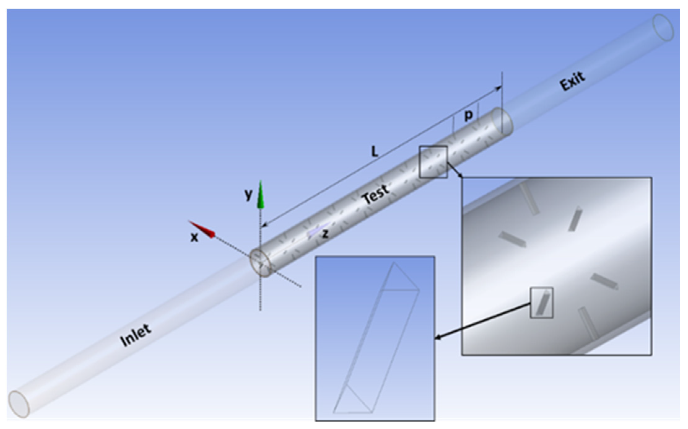
Figure 2.
Meshed domain with enlarged views of the mesh in the cross-section as well as in the partial longitudinal section in the test region.
Figure 2.
Meshed domain with enlarged views of the mesh in the cross-section as well as in the partial longitudinal section in the test region.
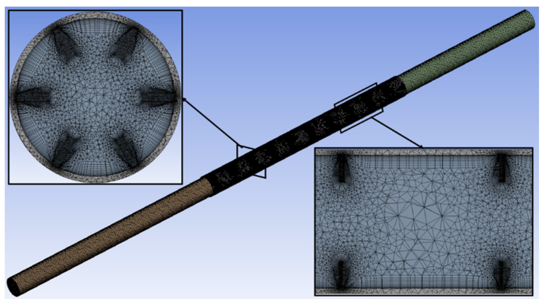
Figure 3.
Comparison of CFD results with the correlations for the smooth pipe: (a) Nusselt number vs. Reynolds number, (b) friction coefficient vs. Reynolds number.
Figure 3.
Comparison of CFD results with the correlations for the smooth pipe: (a) Nusselt number vs. Reynolds number, (b) friction coefficient vs. Reynolds number.

Figure 4.
Effects of different longitudinal pitches on heat transfer and frictional energy loss at fixed angular pitch of 60° and 0° orientations: (a) Nusselt number vs. Reynolds number, (b) friction coefficient vs. Reynolds number.
Figure 4.
Effects of different longitudinal pitches on heat transfer and frictional energy loss at fixed angular pitch of 60° and 0° orientations: (a) Nusselt number vs. Reynolds number, (b) friction coefficient vs. Reynolds number.
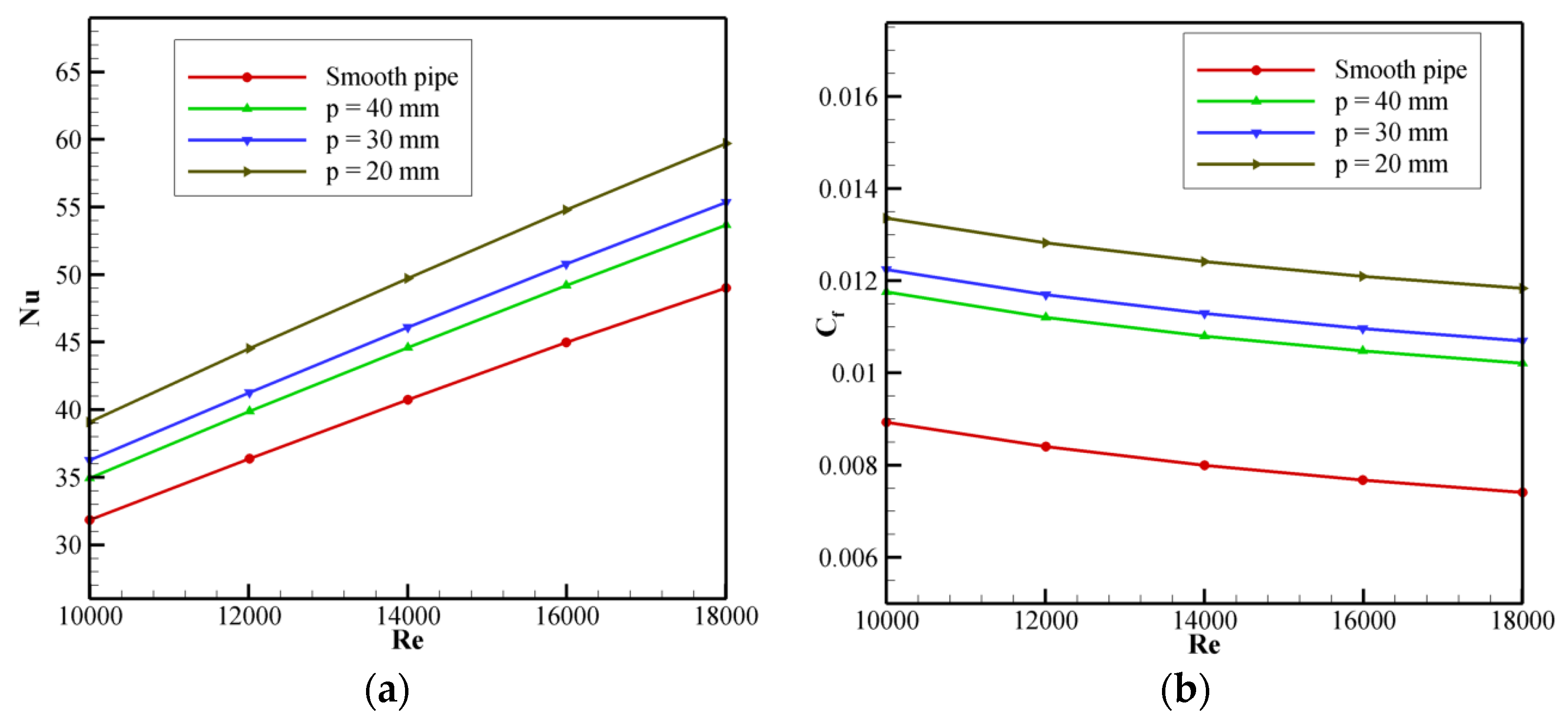
Figure 5.
Velocity (m/s) contours and an enlarged view of velocity vectors downstream of the roughness element in the pipe for different longitudinal pitch arrangements at Re 18,000: (a) 40 mm pitch, (b) 30 mm pitch and (c) 20 mm pitch.
Figure 5.
Velocity (m/s) contours and an enlarged view of velocity vectors downstream of the roughness element in the pipe for different longitudinal pitch arrangements at Re 18,000: (a) 40 mm pitch, (b) 30 mm pitch and (c) 20 mm pitch.
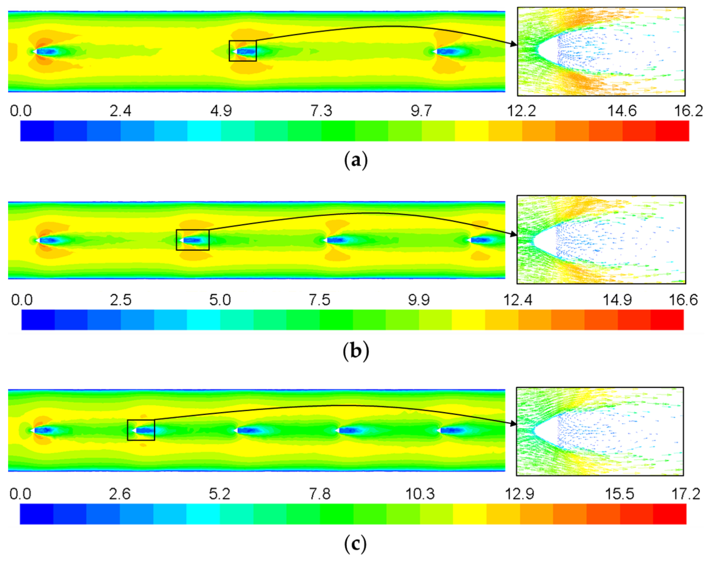
Figure 6.
Pressure (Pa) distribution in the pipe for different longitudinal pitch arrangements at Re 18,000: (a) smooth pipe without roughness elements, (b) 40 mm pitch, (c) 30 mm pitch and (d) 20 mm pitch.
Figure 6.
Pressure (Pa) distribution in the pipe for different longitudinal pitch arrangements at Re 18,000: (a) smooth pipe without roughness elements, (b) 40 mm pitch, (c) 30 mm pitch and (d) 20 mm pitch.

Figure 7.
Effects of different angular pitches on the heat transfer and frictional energy loss at fixed longitudinal pitch of 20 mm and 0° orientations: (a) Nusselt number vs. Reynolds number, (b) friction coefficient vs. Reynolds number.
Figure 7.
Effects of different angular pitches on the heat transfer and frictional energy loss at fixed longitudinal pitch of 20 mm and 0° orientations: (a) Nusselt number vs. Reynolds number, (b) friction coefficient vs. Reynolds number.
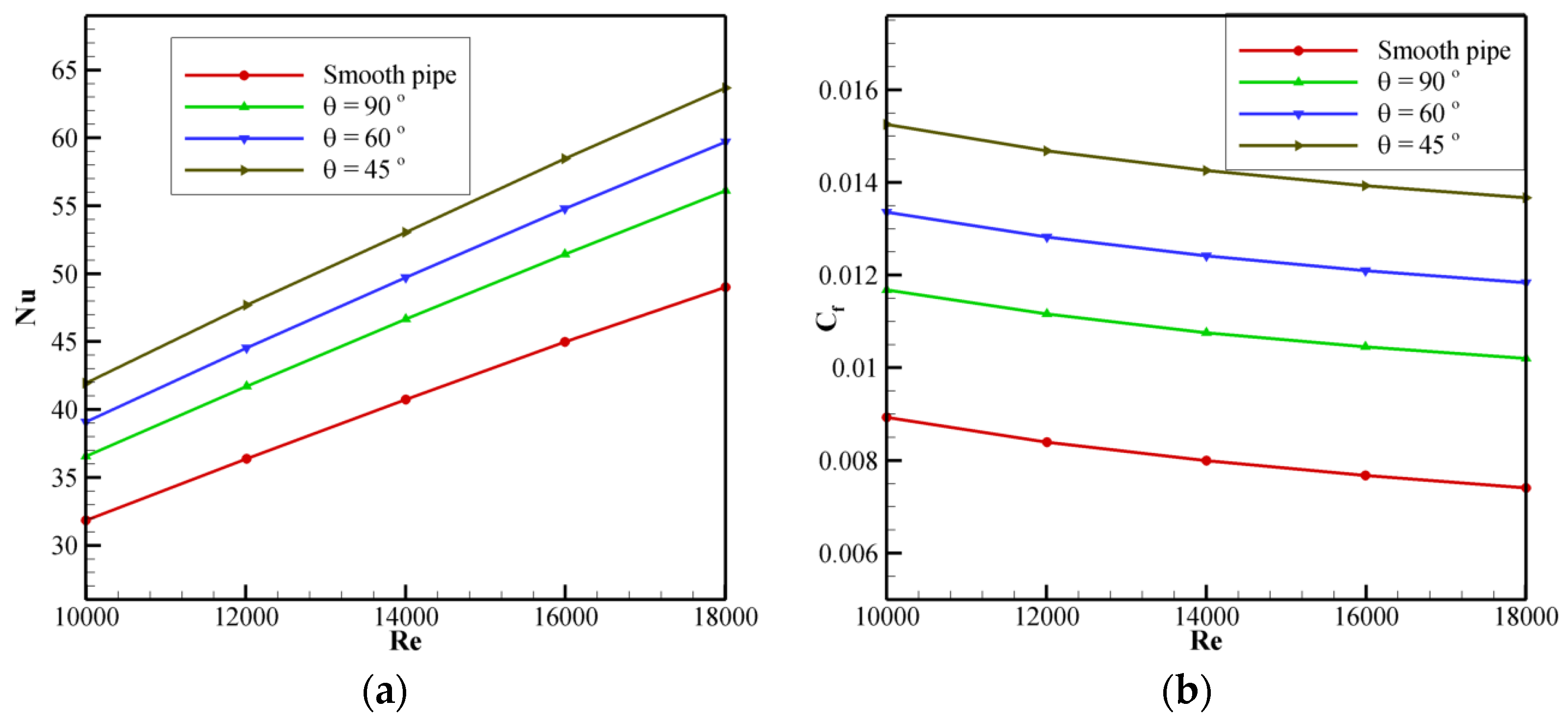
Figure 8.
Effects of orientation of roughness element on the heat transfer and frictional energy loss at fixed longitudinal pitch of 20 mm and angular pitch of 60°: (a) Nusselt number vs. Reynolds number, (b) friction coefficient vs. Reynolds number.
Figure 8.
Effects of orientation of roughness element on the heat transfer and frictional energy loss at fixed longitudinal pitch of 20 mm and angular pitch of 60°: (a) Nusselt number vs. Reynolds number, (b) friction coefficient vs. Reynolds number.


Table 1.
Details of the grid-convergence test.
| Number of Elements | Nu | % Change in Nu | Cf | % Change in Cf |
|---|---|---|---|---|
| 4516639 | 55.16 | ------- | 0.01074 | ------- |
| 5713427 | 55.29 | 0.236 | 0.01071 | −0.279 |
| 6999530 | 55.36 | 0.126 | 0.01069 | −0.187 |
| 9355479 | 55.38 | 0.036 | 0.01069 | 0.000 |
Disclaimer/Publisher’s Note: The statements, opinions and data contained in all publications are solely those of the individual author(s) and contributor(s) and not of MDPI and/or the editor(s). MDPI and/or the editor(s) disclaim responsibility for any injury to people or property resulting from any ideas, methods, instructions or products referred to in the content. |
© 2023 by the author. Licensee MDPI, Basel, Switzerland. This article is an open access article distributed under the terms and conditions of the Creative Commons Attribution (CC BY) license (https://creativecommons.org/licenses/by/4.0/).
Share and Cite
MDPI and ACS Style
Fernandes, D.V. Heat Transfer Enhancement in a Tube Heat Exchanger Using Discrete Triangular-Prism Roughness Elements. Eng. Proc. 2023, 59, 62. https://doi.org/10.3390/engproc2023059062
AMA Style
Fernandes DV. Heat Transfer Enhancement in a Tube Heat Exchanger Using Discrete Triangular-Prism Roughness Elements. Engineering Proceedings. 2023; 59(1):62. https://doi.org/10.3390/engproc2023059062
Chicago/Turabian StyleFernandes, Dolfred Vijay. 2023. "Heat Transfer Enhancement in a Tube Heat Exchanger Using Discrete Triangular-Prism Roughness Elements" Engineering Proceedings 59, no. 1: 62. https://doi.org/10.3390/engproc2023059062