Abstract
Carbon fiber-reinforced aluminum laminates, known as CARALL, have wide applications in aircraft structures. However, numerous holes must be processed to assemble these structures, which is conventionally practiced through drilling. However, the drilling process exhibits certain limitations when utilized for hole-making in heterogeneous materials. In the recent past, helical milling has positioned itself as an alternative to the drilling process. However, helical milling performance examination during hole-making in CARALL is scant and needs further evaluation. The present study compares the milling process to the drilling process considering important performance indices, including cutting forces, surface roughness, chip morphology, machining temperature, and burr size. Additionally, microscopic characterization of the boreholes is performed to verify the presence of surface damage and delamination defects. Helical milling successfully lowered the thrust and radial forces and restrained the machining temperature below the levels attained via drilling. The diametrical deviation is higher at entry and lower at exit for both processes; however, helical milling produced holes with much higher accuracy. Helical milling developed smaller sized holes in comparison to drilling. Moreover, rougher surfaces due to the abrasion of continuous chips were observed in drilling, while a smoother finish was noted in helically milled holes. Based on the comprehensive comparative analysis, helical milling positions itself as an acceptable alternative to conventional drilling for machining fiber metal laminates.
1. Introduction
Fiber metal laminates are multi-layered materials formed by stacking fiber reinforced matrix and metal piles alternatively in a particular predefined sequence and orientation [1]. Aluminum is the most used metal ply [2]. However, titanium, steel, and magnesium are good substitutes. Aramid, carbon, and glass are popular fibrous materials used for reinforcement. FMLs provide great advantages, such as higher fatigue resistance, lower weight, high-temperature resistance, good anti-corrosion properties, and moisture resistance [3]. Additionally, they possess higher impact-absorbing capabilities. Due to the array of advantages, they are widely used in aircraft industries; for example, CARALL is used as an impact absorber for helicopter struts and the fabrication of aircraft seats [4].
FMLs are manufactured to be near net shape. However, several holes are required to assemble the FML structures. In aircraft industries, riveting is the most common method for assembling structural parts [5]. Mechanical drilling is widely used for hole processing in aircraft industries. However, the drilling process has serious drawbacks. Drilling multi-material FMLs is challenging, considering the coupling between the metal and composite phases [6]. The difference in the thermo-mechanical properties of the two phases affects the metal-cutting process. Distinctive properties between the metal and composites can affect the dimensional accuracy of drilled holes [7,8,9]. Also, improper selection of the process variables can increase the thrust load and lower the hole quality [10]. Very high thrust can aid undesirable burr formation [11]. These burrs formed at the periphery of the processed hole can act as crack initiation sites and, thus, lower the fatigue strength [12]. The high cutting temperatures generated via conventional drilling can result in a heat-affected zone (HAZ) and damage the material surface and subsurface [13]. Moreover, the continuous chips generated during conventional drilling can aid in the delamination of composite layers [14]. Drilling-induced delamination affects the structural integrity of the laminate and lowers the load-carrying capacity, while severe internal damage can deteriorate the surface quality and trigger sudden hybrid composite failure [15]. Also, high cutting forces and machining temperatures and the abrasive nature of the composite materials can cause serious tool wear problems [10].
In recent times, researchers have explored the feasibility of employing the helical milling process to suppress the limitations of the drilling processes. The process has gained traction due to its ability to process holes in difficult-to-machine materials like titanium. The kinematics of helical milling presents an advantage from the perspective of machinability. The material undergoes shearing and is subjected to cutting action at the peripheral and axial teeth. The distribution of cutting between the two teeth significantly lowers the magnitude of the cutting forces [16,17]. The reduced work–tool contact lowers the cutting temperatures during helical milling [16,17]. The reduction in the magnitude of cutting forces and temperature, along with the improved chip breakability, helps to lower the surface roughness of the helically milled bores [17,18]. The improved machinability also helps in increasing the cutting tool’s life [19]. Moreover, helically milled holes show reduced plastic deformation and a vast improvement in fatigue life compared to conventionally drilled holes [20] Additionally, the size of the helical milling is smaller than the drilled ones, thereby diminishing the requirements of additional de-burring operations [16]. As reported in the literature, helical milling is a versatile operation that can process holes in difficult-to-machine materials. However, scant literature is available on the machinability of FMLs using helical milling. As a result, a gap exists concerning the behavior of process variables and process kinematics in terms of various performance indicators like hole quality and process productivity. Therefore, the current work comparatively analyses drilling with helical milling for processing holes in CARALL and explores the performance by considering cutting forces, surface roughness, chip morphology, machining temperature, and burr size.
2. Materials and Methods/Methodology
CARALL FMLs were manufactured using 2024 aluminum alloy sheets (0.5 mm thick) and unidirectional carbon fiber prepreg (0.2 mm thick). The carbon fiber in the prepreg has a modulus of 240 GPa and a tensile strength of 4000 MPa. The matrix was made of Epoxy A45, and the resin content in the prepreg was 38%. The carbon fiber prepreg has a density of 1.8 g/cm3 and an areal weight of 200 GSM. The FMLs were cured in two stages at a prescribed temperature and pressure using an autoclave technique, as shown in Figure 1. For the fabrication, the two materials were stacked alternately, as shown in Figure 2a. Unidirectional carbon fiber prepregs were oriented in the aluminum rolling direction. The temperature increased from ambient to 80 °C at a controlled rate of 2 °C/min. After a dwell period of 30 min, the temperature was increased to 130 °C and held in position for 90 min. During the curing process, the pressure was maintained at 6 bar. Figure 2b displays the fabricated CARALL specimen.
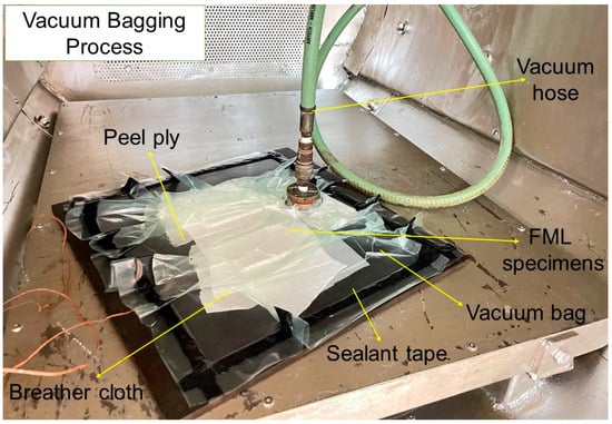
Figure 1.
Specimen preparation using a vacuum bagging setup in an autoclave.
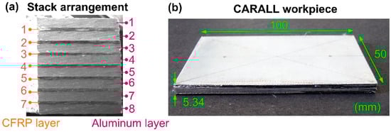
Figure 2.
(a) Stack arrangement in the fabricated CARALL specimen. (b) Fabricated CARALL specimen.
The experimental study was conducted to evaluate the performance indices, including cutting forces, machining temperature, surface roughness, chip morphology, and burr size for both hole-making processes. Additionally, microscopic characterization of the boreholes was performed to verify the presence of surface damage and delamination defects. Machining trials were conducted on a Vertical Machining Center (VMC), using the setup shown in Figure 3a. The drilling was conducted using a 6.8 mm twist drill, while helical milling tests were carried out using a 5 mm end mill, as shown in Figure 3b. Table 1 lists the process variables selected for experimentation. Experimentation used three cutting speeds of 30, 60, and 90 m/min, keeping the feed constant. The parity between the two hole-making processes was maintained by keeping the machining time similar and maintaining a constant feed.
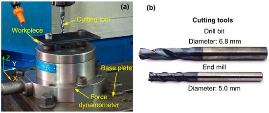
Figure 3.
(a) Helical milling experimental setup. (b) Cutting tools used.

Table 1.
Process variables for comparative evaluation.
3. Results
3.1. Cutting Forces
Figure 4 depicts the behavior of thrust force and resultant radial forces with the cutting speeds for both processes. The cutting force magnitude is lower during the helical milling process. For example, the thrust force magnitude (Case 3) recorded during the drilling operation was 157.3 N, while the helical milling was 62.5 N (see Figure 4a). The radial force generated for the two hole-making operations shows a trend similar to a thrust force. The resultant radial during the drilling operation was 101.7 N, while the helical milling had a magnitude of 39.8 N (see Figure 4b).
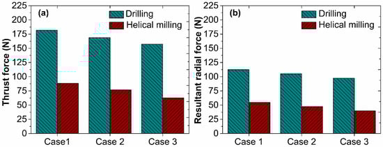
Figure 4.
Variation in (a) thrust force with cutting speed and (b) resultant radial force with cutting speed.
3.2. Chip Morphology
Figure 5 displays the chips formed during the two hole-making operations. Drilling produced long continuous chips, while helical milling produced short discontinuous chips (see Figure 5. The production of such discontinued chips is preferable for easy chip evacuation and its ability to minimize surface damage.
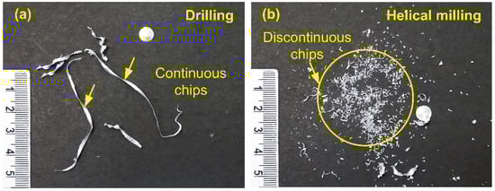
Figure 5.
Chip shape and size during (a) drilling and (b) helical milling.
3.3. Surface Roughness
Figure 6 presents the comparison of surface roughness values between drilled and milled hole surfaces. As noticed, the surface roughness of drilled holes was higher when compared to helically milled ones. The highest surface roughness was obtained from Case 1. Drilling resulted in a surface roughness value of 4.8 µm, whereas helical milling had a lower roughness value of 3.1 µm for Case 1.
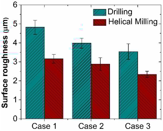
Figure 6.
Surface roughness vs. cutting speed.
3.4. Machining Temperature
Figure 7 gives the comparison between machining temperatures for drilling and helical milling operations for three cases. A higher machining temperature was observed in drilling than in helical milling for all the test cases. The machining temperature developed during drilling was 155.6 °C, and in the helical milling process, it was 114.4 °C. The maximum temperature resulted in Case 3.
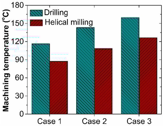
Figure 7.
Machining temperature vs. cutting speed.
3.5. Diametrical Accuracy
Figure 8 shows that both operations generated holes that were larger than the nominal dimension (6.8 mm). However, the diametrical deviation was higher in the drilled holes in comparison to the helically milled holes. The diametrical deviation was higher at the entry compared to the exit hole, a similar trend was observed for all the cases and both hole-making processes.
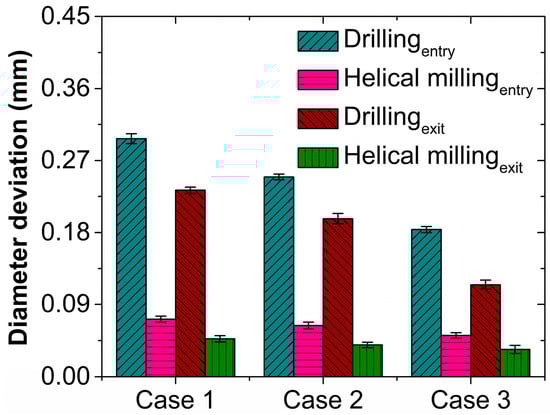
Figure 8.
Diameter deviation vs. cutting speed.
3.6. Burr Formation
Figure 9a,b compares the burr height and burr width obtained for all three cases, respectively, for both hole-making processes. Burrs of prominent size were observed in the drilled holes, and relatively small-sized burrs were observed for helical milling. The highest burr sizes resulted in Case 3 for both processes.
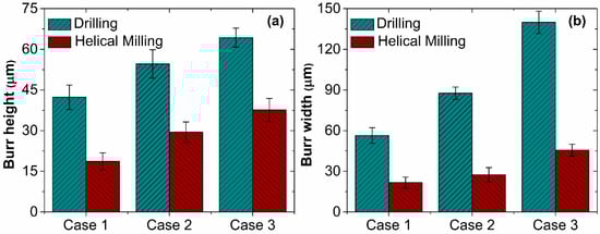
Figure 9.
(a) Burr height vs. cutting speed. (b) Burr width vs. cutting speed.
3.7. SEM Analysis of Hole Surface
Figure 10a,b provides the scanning electron microscope images of the machined hole surfaces for drilling and helical milling, respectively. Ply delamination was observed in a hole drilled using a higher speed and feed. However, the helical milling generated damage-free holes, even under similar processing conditions.
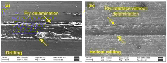
Figure 10.
(a) Ply delamination during drilling. (b) Damage-free helically milled workpiece.
4. Discussion
4.1. Cutting Forces
Drilling resulted in a higher thrust force magnitude, which is attributed to the full contact of the frontal chisel edges of the drill with the workpiece. However, a reduction in thrust force magnitude is observed during helical milling and ascribed to the force distribution between the axial and peripheral cutting edges of end mill. The higher radial force magnitude observed during the drilling operation is linked to the chip evacuation mechanism. In conventional drilling, tool flutes extrude the strain-hardened chips from the machining zone. In the process, they abrade the bore surface, thus raising the frictional and radial loads. However, smaller end mill tools evacuate the chips quickly without raising the frictional load. Furthermore, observation reveals that the force components decrease with increasing cutting speed (see Figure 4. The decrease in the force magnitude with the cutting speed is attributed to material thermal softening due to the higher cutting temperature.
4.2. Chip Morphology
The continuous chips generated during drilling (see Figure 5a) caused damage to the drilled hole surface and even played a prominent role in increasing the cutting forces and machining temperatures. The continuous chips were produced as a result of an unrestricted flow of chips through the flutes of a drill bit. On the other hand, the helical milling kinematics enabled chip breakability and served as a primary reason for generating discontinuous chips (see Figure 5b). Chips, thus, had little interaction with the hole surface, even assisting in reducing the cutting forces and temperatures.
4.3. Surface Roughness
Drilling yielded a higher surface roughness value, resulting from grooves generated on the hole surface by the strain-hardened chips. In contrast, lower surface roughness in milled holes is attributed to process kinematics. The difference in the tool and bore diameters provides enough space for interference-free chip evacuation. As observed from Figure 6, the surface roughness decreased as the cutting speed increased. A reduction in the magnitude of cutting forces at higher cutting speeds helped to improve surface finish.
4.4. Machining Temperature
As noticed, drilling yielded higher machining temperatures. Uninterrupted contact between the twist drill and bore surface in conventional drilling increased the frictional load and, hence, the temperature. However, intermittent work–tool contact during helical milling helped to dissipate the generated heat and lower the machining temperatures. As seen in Figure 7, the machining temperature intensified with the utilization of higher cutting speeds. The reduced interaction time at higher speeds lowered the heat conduction capacity of the machined chips. It must be noted that the temperatures generated during drilling are significantly higher than the glass transition temperature of epoxy resin (130 °C). However, the temperatures measured during helical milling were located within the acceptable limit.
4.5. Diameterical Accuracy
Higher diametrical deviation in drilled holes was observed, which is attributed to the larger thrust force. In addition, chips evacuated through the flues of the twist drill also aided in enlarging the size of the hole. In helical milling, load distribution lowers the thrust force, thus producing holes with lower diametrical deviations. The effect of the cutting speed on diametrical deviation can be seen in Figure 8. A decrease in diametrical deviation with the increase in cutting speed results from improved process stability and decreased milling force at high cutting speeds.
4.6. Burr Formation
Drilling resulted in larger-sized burrs, which is attributed to the thrust force. Excessive thrust force and the accompanying plastic deformation stretched the work material, generating large burrs. However, a lower thrust load during helical milling produced smaller-sized burrs. However, the sizes of the burrs increased as the cutting speed increased, which is evident in Figure 9. This increase is attributed to the higher cutting temperatures and plastic deformation observed at higher cutting speeds.
4.7. SEM Analysis of Hole Surface
The surface morphology study of the drilled holes revealed delamination, as seen in Figure 10a, which is attributed to the higher cutting forces and temperature. Intermittent cutting and lower thrust forces and machining temperatures produced during helically milled holes helped to produce delamination-free interfaces (see Figure 10b) on the surfaces of machined holes.
5. Conclusions
The results demonstrate that helical milling can lower the magnitude of cutting forces and machining temperature. Also, holes processed via helical milling showed superior surface finish and diametrical accuracy. Burr size was lower than the mechanical drilling process. Also, the generation of powdery chips enables easy chip evacuation. Overall, the outcome of the work suggests that helical milling is advantageous for making holes in FMLs. However, further evaluation is needed to optimize the helical milling process to obtain an absolutely defect-free hole.
Author Contributions
Conceptualization, S.S.B. and G.B.; methodology, M.B.; validation, M.B.; formal analysis, M.B.; investigation, M.B.; data curation, G.B.; writing—original draft preparation, M.B.; writing—review and editing, G.B. and S.S.B.; supervision, G.B. and S.S.B.; project administration, G.B. and S.S.B.; funding acquisition, G.B. All authors have read and agreed to the published version of the manuscript.
Funding
This research was funded via an intramural grant from the Manipal Academy of Higher Education (MAHE), Manipal.
Institutional Review Board Statement
Not applicable.
Data Availability Statement
All the data are provided in the manuscript.
Conflicts of Interest
The authors declare there is no conflict of interest.
References
- Asundi, A.; Choi, A.Y.N. Fiber metal laminates: An advanced material for future aircraft. J. Mater. Process. Technol. 1997, 63, 384–394. [Google Scholar] [CrossRef]
- Dursun, T.; Soutis, C. Recent developments in advanced aircraft aluminum alloys. Mater. Des. (1980–2015) 2014, 56, 862–871. [Google Scholar] [CrossRef]
- Ding, Z.; Wang, H.; Luo, J.; Li, N. A review on forming technologies of fibre metal laminates. Int. J. Lightweight Mater. Manuf. 2021, 4, 110–126. [Google Scholar] [CrossRef]
- Sinmazçelik, T.; Avcu, E.; Bora, M.Ö.; Çoban, O. A review: Fibre metal laminates, background, bonding types and applied test methods. Mater. Des. 2011, 32, 3671–3685. [Google Scholar] [CrossRef]
- Kalidas, S.; DeVor, R.E.; Kapoor, S.G. Experimental investigation of the effect of drill coatings on hole quality under dry and wet drilling conditions. Surf. Coat. Technol. 2001, 148, 117–128. [Google Scholar] [CrossRef]
- Xu, J.; El Mansori, M. Experimental study on drilling mechanisms and strategies of hybrid CFRP/Ti stacks. Compos. Struct. 2016, 157, 461–482. [Google Scholar] [CrossRef]
- Brinksmeier, E.; Janssen, R. Drilling of Multi-Layer Composite Materials consisting of Carbon Fiber Reinforced Plastics (CFRP), Titanium and Aluminum Alloys. CIRP Ann. 2002, 51, 87–90. [Google Scholar] [CrossRef]
- Qi, Z.; Zhang, K.; Li, Y.; Liu, S.; Cheng, H. Critical thrust force predicting modeling for delamination-free drilling of metal-FRP stacks. Compos. Struct. 2014, 107, 604–609. [Google Scholar] [CrossRef]
- Costa, R.D.F.S.; Sales-Contini, R.C.M.; Silva, F.J.G.; Sebbe, N.; Jesus, A.M.P. A Critical Review on Fiber Metal Laminates (FML): From Manufacturing to Sustainable Processing. Metals 2023, 13, 638. [Google Scholar] [CrossRef]
- Zitoune, R.; Krishnaraj, V.; Collombet, F. Study of drilling of composite material and aluminium stack. Compos. Struct. 2010, 92, 1246–1255. [Google Scholar] [CrossRef]
- Jin, S.Y.; Pramanik, A.; Basak, A.K.; Prakash, C.; Shankar, S.; Debnath, S. Burr formation and its treatments—A review. Int. J. Adv. Manuf. Technol. 2020, 107, 2189–2210. [Google Scholar] [CrossRef]
- Aurich, J.C.; Dornfeld, D.; Arrazola, P.J.; Franke, V.; Leitz, L.; Min, S. Burrs—Analysis, control and removal. CIRP Ann. 2009, 58, 519–542. [Google Scholar] [CrossRef]
- Marques, F.; Silva, F.G.A.; Silva, T.E.F.; Rosa, P.A.R.; Marques, A.T.; de Jesus, A.M.P. Delamination of Fibre Metal Laminates Due to Drilling: Experimental Study and Fracture Mechanics-Based Modelling. Metals 2022, 12, 1262. [Google Scholar] [CrossRef]
- Hemant, K.; Kona, A.; Karthik, S.A.; Bolar, G. Experimental investigation into helical hole milling of fiber metal laminates. Mater. Today Proc. 2019, 27, 208–216. [Google Scholar] [CrossRef]
- Khashaba, U. Delamination in Drilling GFR-Thermoset Composites. In Proceedings of the International Conference on Aerospace Sciences and Aviation Technology, Military Technical College, Cairo, Egypt, 9–13 May 2003. [Google Scholar]
- Wang, B.; Chang, K.; Wang, M.; Zhang, F.; Zhang, Y.; Zheng, Y. Experimental studies on helical milling process to improve hole quality for the Superalloy (MSRR7197). Int. J. Adv. Manuf. Technol. 2018, 99, 1449–1458. [Google Scholar] [CrossRef]
- Akula, S.; Bolar, G. Comparative evaluation of machining processes for making holes in GLARE fiber metal laminates. Mater. Today Proc. 2021, 46, 9126–9131. [Google Scholar] [CrossRef]
- Iyer, R.; Koshy, P.; Ng, E. Helical milling: An enabling technology for hard machining precision holes in AISI D2 tool steel. Int. J. Mach. Tools. Manuf. 2007, 47, 205–210. [Google Scholar] [CrossRef]
- Li, H.; He, G.; Qin, X.; Wang, G.; Lu, C.; Gui, L. Tool wear and hole quality investigation in dry helical milling of Ti-6Al-4V alloy. Int. J. Adv. Manuf. Technol. 2014, 71, 1511–1523. [Google Scholar] [CrossRef]
- Wang, G.-D.; Suntoo, D.; Li, N.; Peng, T.; Li, Y. Experimental research in CFRP/Ti stack through different helical milling strategies. Int. J. Adv. Manuf. Technol. 2018, 98, 3251–3267. [Google Scholar] [CrossRef]
Disclaimer/Publisher’s Note: The statements, opinions and data contained in all publications are solely those of the individual author(s) and contributor(s) and not of MDPI and/or the editor(s). MDPI and/or the editor(s) disclaim responsibility for any injury to people or property resulting from any ideas, methods, instructions or products referred to in the content. |
© 2023 by the authors. Licensee MDPI, Basel, Switzerland. This article is an open access article distributed under the terms and conditions of the Creative Commons Attribution (CC BY) license (https://creativecommons.org/licenses/by/4.0/).