Technological Research of a Clean Energy Router Based on Advanced Adiabatic Compressed Air Energy Storage System


Abstract
:1. Introduction
2. AA-CAES System
2.1. The Working Principle of AA-CAES
2.2. Compound CAES
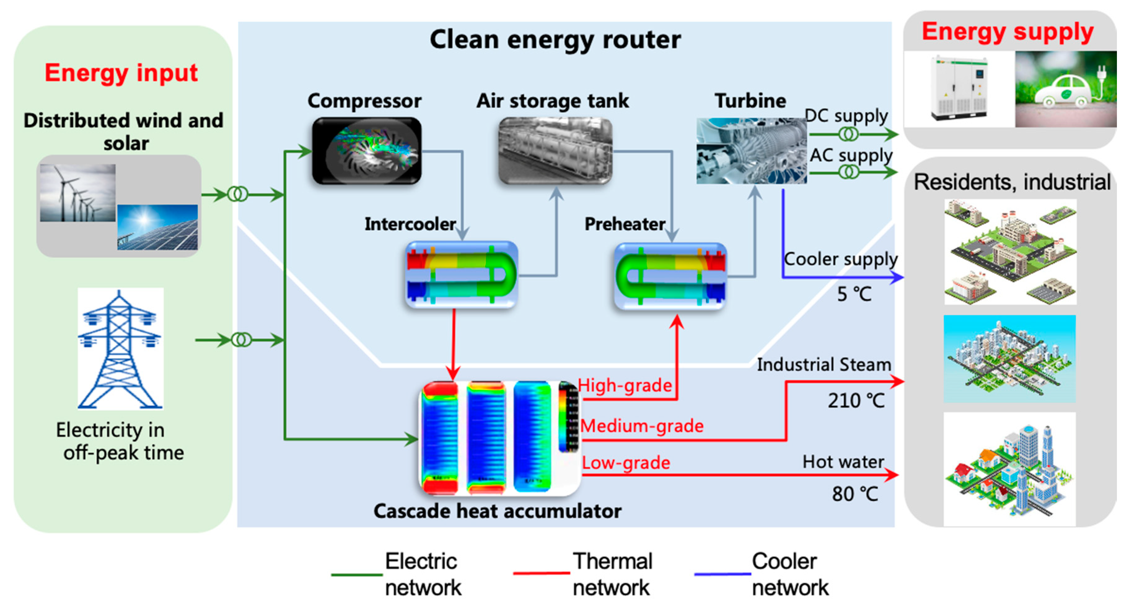
3. The CER
Coupling Architecture and Working Mode
4. Thermodynamic Simulation Model of AA-CAES
4.1. Compressor Module
4.2. Heat Exchanger Module
4.2.1. Heat Exchanger on the Compression Side
4.2.2. Heat Exchanger on the Expansion Side
4.3. Thermal Storage Module
4.4. AST Module
4.5. Turbine Module
5. Energy Flow Analysis and Conversion Mechanism
5.1. Heating Energy Produced
5.2. Cooling Energy Produced
5.3. Overall Energy Storage Efficiency
6. Simulation and Results
6.1. Charging Process
6.2. Discharging Process
6.3. The Whole System Operation Process
7. Conclusions
- The results show the outlet pressure change of the compressor under the two conditions of the adiabatic and heat exchange of the AST. When considering the heat exchange of the AST, the sixth stage of the compressor reached a stable pressure in 3.4 h compared with 2.5 h under the adiabatic conditions of the AST. The adiabatic conditions of the AST were closer to the actual situation when we need to consider the comparison with the actual data of the system.
- The results of the discharging process demonstrated that the adiabatic and heat exchange of the AST did not influence the outlet pressure of the turbine, and, thus, meet the requirements of the design. Meanwhile, it is essential to consider the heat exchange of the medium-temperature thermal storage unit due to the accuracy of the model.
- Finally, the efficiency of the system was analyzed based on two aspects: First, the efficiency of the power exchange was obtained by the ratio between the power consumption and the power generation as 56.5%. Second, the overall efficiency of the system reached 93.6% from the perspective of the CEU rate of the combination of cooling, heating, and electric energy.
Author Contributions
Funding
Conflicts of Interest
Nomenclature
| EI | Energy Internet |
| AA-CAES | Advanced adiabatic compressed air energy storage system |
| CER | Clean energy router |
| CEU | Comprehensive energy utilization |
| RE | Renewable energy |
| DG | Distributed generation |
| AC | Alternating current |
| DC | Direct current |
| ESS | Energy storage system |
| PHS | Pumped hydroelectric storage system |
| BES | Battery energy storage system |
| REN | Regional energy network |
| CAES | Compressed air energy storage system |
| CTS | Cascade thermal storage system |
| AST | Air storage tank |
| CCHP | Combined cooling, heating, and power |
References
- Xue, X.; Mei, S.; Lin, Y.; Chen, L.; Chen, Y. Energy Internet oriented non-supplementary fired compressed air energy storage and prospective of application. Power Syst. Technol. 2016, 40, 164–171. [Google Scholar]
- Phebe, A.; Samuel, A. A review of renewable energy sources, sustainability issues and climate change mitigation. Cogent Eng. 2016, 3, 1167990. [Google Scholar]
- Sun, J.; Wang, Z.; Li, G. Measuring emission-reduction and energy-conservation efficiency of Chinese cities considering management and technology heterogeneity. J. Clean. Prod. 2018, 175, 561–571. [Google Scholar] [CrossRef]
- Rifkin, J. The Third Industrial Revolution: How Lateral Power is Transforming Energy, the Economy and the World. Available online: https://edisciplinas.usp.br/pluginfile.php/5086400/mod_label/intro/epdf.pub_the-third-industrial-revolution.pdf (accessed on 18 September 2020).
- Venkataramani, G.; Parankusam, P.; Ramalingam, V.; Wang, J. A review on compressed air energy storage—A pathway for smart grid and polygeneration. Renew. Sustain. Energy Rev. 2016, 62, 895–907. [Google Scholar] [CrossRef]
- Audrius, B.; Nick, J. Exergy and exergoeconomic analysis of a compressed air energy storage combined with a district energy system. Energy Convers. Manag. 2014, 77, 432–440. [Google Scholar]
- Ahmad, T.; Zhang, H.; Yan, B. A review on renewable energy and electricity requirement forecasting models for smart grid and buildings. Sustain. Cities Soc. 2020, 55, 102052. [Google Scholar] [CrossRef]
- Wang, J.; Lu, K.; Ma, L.; Wang, J.; Dooner, M.; Miao, S.; Li, J.; Wang, D. Overview of compressed air energy storage and technology development. Energies 2017, 10, 991. [Google Scholar] [CrossRef] [Green Version]
- Jams, A.; Han, G.; Liu, L.; Peng, Y.; Mohsin, K. Optimal resource allocation in energy-efficient Internet-of-things networks with imperfect CSI. J. IEEE Internet Things J. 2020, 6, 10846–10854. [Google Scholar]
- Geidl, M.; Andersson, G. Optimal power flow of multiple energy carriers. J. IEEE Trans. Power Syst. 2007, 22, 145–155. [Google Scholar] [CrossRef]
- Geidel, M.; Koeppel, G.; Favre, P. Energy hubs for the future. J. Power Energy Mag. IEEE 2007, 5, 24–30. [Google Scholar] [CrossRef]
- Neyestani, N.; Yazdani, D.; Shafie, K. Stochastic modeling of multienergy carriers dependencies in smart local networks with distributed energy resources. J. IEEE Trans. Smart Grid 2015, 6, 1748–1762. [Google Scholar] [CrossRef]
- Manshadi, S.; Khodayar, M. Resilient operation of multiple energy carrier microgrids. J. IEEE Trans. Smart Grid 2015, 6, 2283–2292. [Google Scholar] [CrossRef]
- Katz, R.; Culler, D.; Sanders, S. An information-centric energy infrastructure: The Berkeley view. J. Sustain. Comput. Inform. Syst. 2011, 1, 7–22. [Google Scholar] [CrossRef]
- Guo, H.; Wang, F.; Zhang, L.; Luo, J. A hierarchical optimization strategy of the energy router based energy Internet. IEEE Trans. Power Syst. 2020, 34, 4177–4185. [Google Scholar] [CrossRef]
- Zhang, X.; Chen, H.; Liu, J.; Li, W.; Tan, C. Research progress in compressed air energy storage system: A review. J. Energy Storage Sci. Technol. 2012, 1, 26–40. [Google Scholar]
- Arabkoohsar, A.; Dremark-Larsen, M.; Lorentzen, R.; Andresen, G.B. Subcooled compressed air energy storage system for coproduction of heat, cooling and electricity. Appl. Energy 2017, 205, 602–614. [Google Scholar] [CrossRef]
- Wang, S.; Zhang, X.; Yang, L.; Zhou, Y.; Wang, J. Experimental study of compressed air energy storage system with thermal energy storage. Energy 2016, 103, 182–191. [Google Scholar] [CrossRef]
- Bergman, T.; Incropera, F.; DeWitt, D. Fundamentals of Heat and Mass Tranzsfer; John Wiley & Sons: Hoboken, NJ, USA, 2011; pp. 706–727. [Google Scholar]
- Zhang, W.; Xue, X.; Liu, F.; Mei, S. Modelling and experimental validation of advanced adiabatic compressed air energy storage with off-design heat exchanger. IET Renew. Power Gener. 2020, 14, 389–398. [Google Scholar] [CrossRef]
- Liu, W.; Li, Q.; Liang, F.; Liu, L.; Xu, G.; Yang, Y. Performance analysis of a coal-fired external combustion compressed air energy storage system. Entropy 2014, 16, 5935–5953. [Google Scholar] [CrossRef] [Green Version]
- Kim, Y.; Favrat, D. Energy and exergy analysis of a micro-compressed air energy storage and air cycle heating and cooling system. Energy 2010, 35, 213–220. [Google Scholar] [CrossRef] [Green Version]
- Geissbühler, L.; Becattini, V.; Zanganeh, G. Pilot-scale demonstration of advanced adiabatic compressed airenergy storage, part 1: Plant description and tests with sensible thermal-energy storage. J. Energy Storage 2018, 17, 129–139. [Google Scholar] [CrossRef]
- Jakiel, C.; Zunft, S.; Nowi, A. Adiabatic compressed air energy storage plants for efficient peak load power supply from wind energy: The european project AA-CAES. Int. J. Energy Technol. Policy 2007, 5, 296–306. [Google Scholar] [CrossRef]
- Sciacovelli, A.; Li, Y.; Chen, H. Dynamic simulation of adiabatic compressed air energy storage (A-CAES) plant with integrated thermal storage–link between components performance and plant performance. Appl. Energy 2017, 185, 16–28. [Google Scholar] [CrossRef] [Green Version]
- Houssainy, S.; Janbozorgi, M.; Kavehpour, P. Performance of an isobaric hybrid compressed air energy storage system at minimum entropy generation. J. Energy Resour. Technol. 2020, 142, 1–20. [Google Scholar] [CrossRef]
- Julian, D.; Rob, H.; Juan, C. Effect of multi-tank thermal energy storage, recuperator effectiveness, and solar receiver conductance on the performance of a concentrated solar supercritical CO2-based power plant operating under different seasonal conditions. Energy 2016, 115, 353–368. [Google Scholar]
- Steta, D. Modeling of an Advanced Adiabatic Compressed Air Energy Storage (AA-CAES) Unit and an Optimal Model-Based Operation Strategy for Its Integration into Power Markets; EEH Power Systems Laboratory Swiss Federal Institute of Technology (ETH): Zurich, Switzerland, 2010. [Google Scholar]
- Oliver, G.; Malte, B.; Reinhold, K. Increasing fossil power plant flexibility by integrating molten-salt thermal storage. Energy 2017, 118, 876–883. [Google Scholar]
- Li, R.; Wang, H.; Zhang, H. Dynamic simulation of a cooling, heating and power system based on adiabatic compressed air energy storage. Renew. Energy 2019, 138, 326–339. [Google Scholar] [CrossRef]
- Chen, L.; Xie, M.; Zhao, P. A novel isobaric adiabatic compressed air energy storage (ia-caes) system on the base of volatile fluid. Appl. Energy 2018, 210, 198–210. [Google Scholar] [CrossRef]
- Abbasi, M.; Chahartaghi, M.; Hashemian, S.M. Energy, exergy and economic evaluations of a CCHP system by using the internal combustion engines and gas turbine as prime movers. Energy Convers. Manag. 2018, 173, 359–374. [Google Scholar] [CrossRef]


| Parameters | Value | Unit |
|---|---|---|
| Compressor isentropic efficiency | 0.84 | / |
| Turbine isentropic efficiency | 0.9 | / |
| Air mass flow of compressor | 7.39 | kg/s |
| Air mass flow of turbine | 14.46 | kg/s |
| Air mass flow of thermal storage medium | 2.18 | kg/s |
| Specific heat capacity of air at constant pressure | 1005 | J/kg·k |
| The specific heat capacity of water | 4200 | J/kg·k |
| Air constant | 287 | J/kg·k |
| Heat transfer coefficient between air and the outside of the tank | 30 | W/(m2·k) |
| Ambient temperature | 293 | K |
| Ambient pressure | 0.1015 | MPa |
| Compression period | 8 | h |
| Expansion period | 4 | h |
| Parameters | AA-CAES | CCHP |
|---|---|---|
| Round trip efficiency, % | 93.6 | 87% |
| Electric to electric efficiency, % | 56.5 | / |
| Exergy efficiency, % | / | 80% |
Publisher’s Note: MDPI stays neutral with regard to jurisdictional claims in published maps and institutional affiliations. |
© 2020 by the authors. Licensee MDPI, Basel, Switzerland. This article is an open access article distributed under the terms and conditions of the Creative Commons Attribution (CC BY) license (http://creativecommons.org/licenses/by/4.0/).
Share and Cite
Ni, C.; Xue, X.; Mei, S.; Zhang, X.-P.; Chen, X. Technological Research of a Clean Energy Router Based on Advanced Adiabatic Compressed Air Energy Storage System. Entropy 2020, 22, 1440. https://doi.org/10.3390/e22121440
Ni C, Xue X, Mei S, Zhang X-P, Chen X. Technological Research of a Clean Energy Router Based on Advanced Adiabatic Compressed Air Energy Storage System. Entropy. 2020; 22(12):1440. https://doi.org/10.3390/e22121440
Chicago/Turabian StyleNi, Chenyixuan, Xiaodai Xue, Shengwei Mei, Xiao-Ping Zhang, and Xiaotao Chen. 2020. "Technological Research of a Clean Energy Router Based on Advanced Adiabatic Compressed Air Energy Storage System" Entropy 22, no. 12: 1440. https://doi.org/10.3390/e22121440
APA StyleNi, C., Xue, X., Mei, S., Zhang, X.-P., & Chen, X. (2020). Technological Research of a Clean Energy Router Based on Advanced Adiabatic Compressed Air Energy Storage System. Entropy, 22(12), 1440. https://doi.org/10.3390/e22121440