Decision Tree-Based Sensitive Information Identification and Encrypted Transmission System

Abstract
:1. Introduction
- ●
- The decision tree model is readable and descriptive, which is helpful for manual analysis;
- ●
- It is highly efficient: the decision tree only needs to be constructed once and is used repeatedly; the maximum calculation time of each prediction cannot exceed the depth of the decision tree [12].
2. Sensitive Information Identification
2.1. Decision Tree
2.2. Information Gain
2.2.1. The Meaning of Information Entropy to a Decision Tree
2.2.2. Information Gain
2.3. Constructing a Classifier with Feature Faces
2.3.1. Principal Component Analysis
- Zero averaging: take the mean of each column, and then subtract the mean from all the numbers in that column;
- Find the covariance matrix of this matrix;
- Evaluate the eigenvalue and eigenmatrix;
- Retain the main components (i.e., retain the first n features with large retention values).
2.3.2. Building a Decision Tree with Sklearn
3. Encrypted Transmission System
3.1. Basic Functions of the SM4 Encryption Algorithm
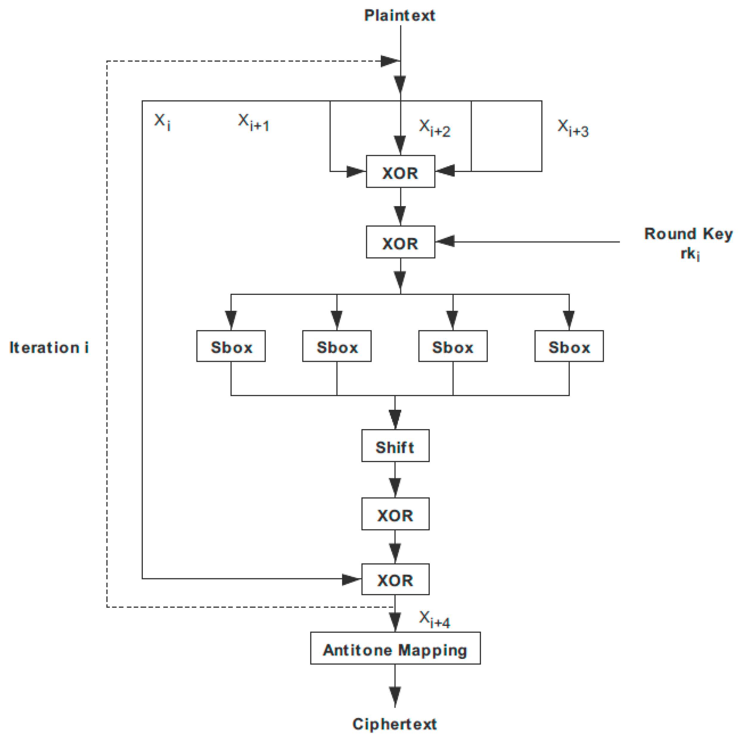
3.2. SM4 Encryption Algorithm Encryption and Decryption Process
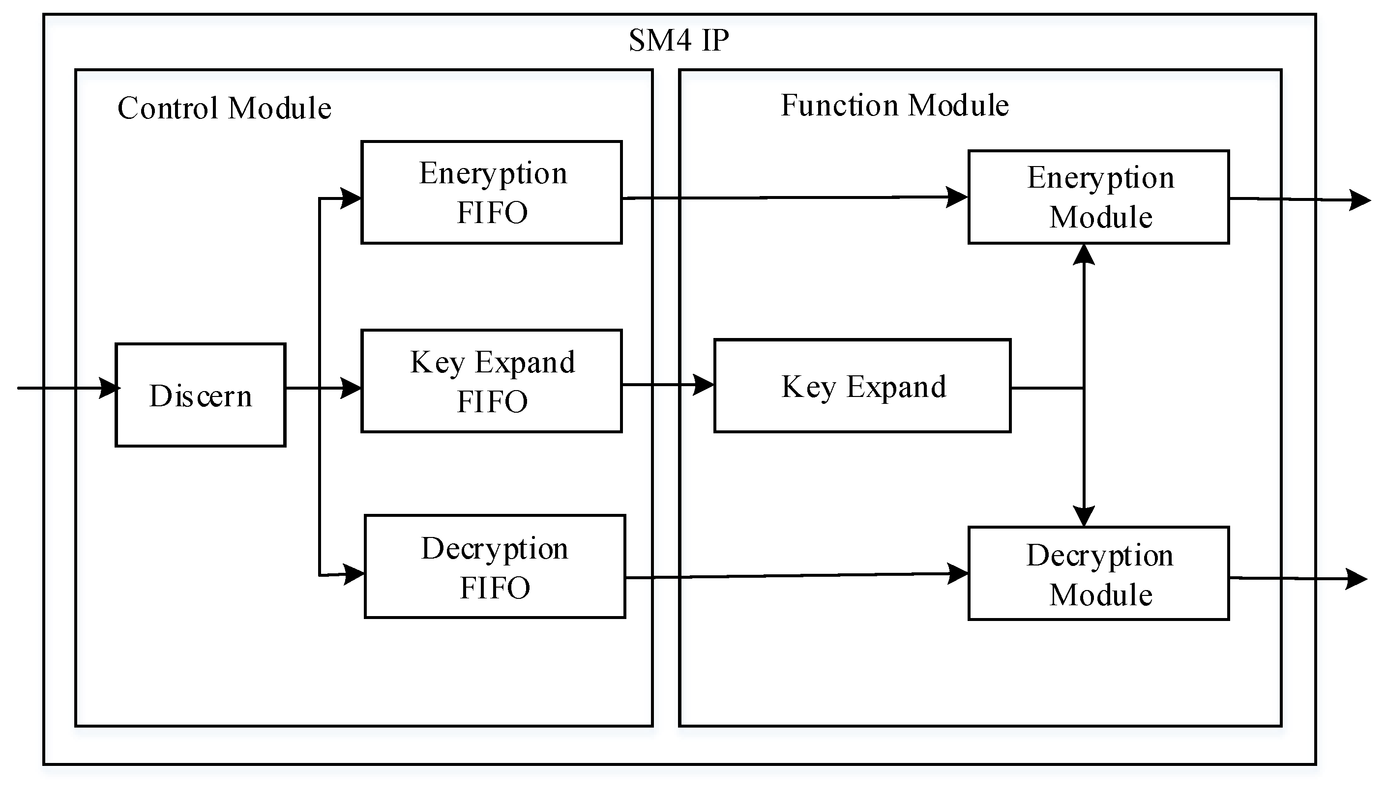
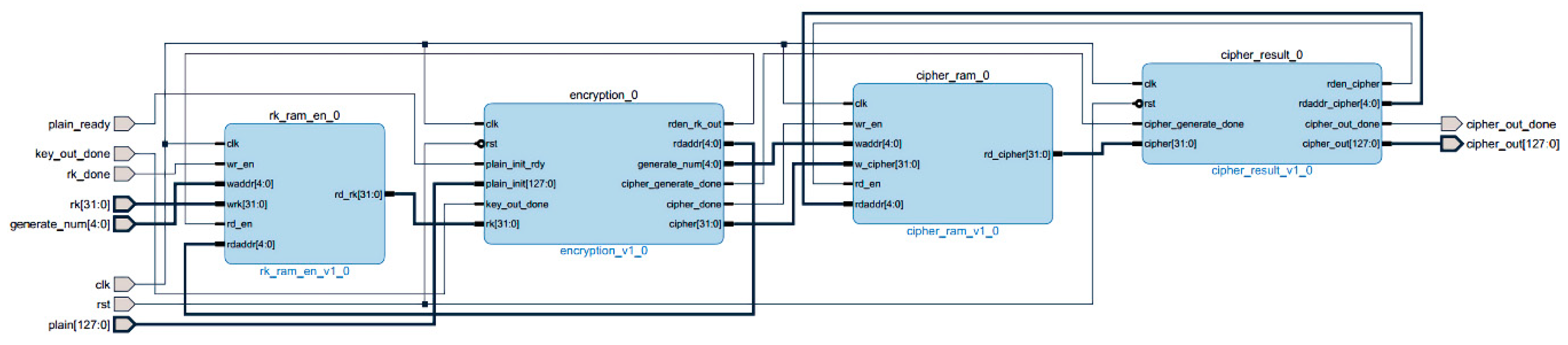
3.3. SM4 Encryption IP Core Design
3.4. Hardware Implementation
3.4.1. PL-Side Design and Implementation
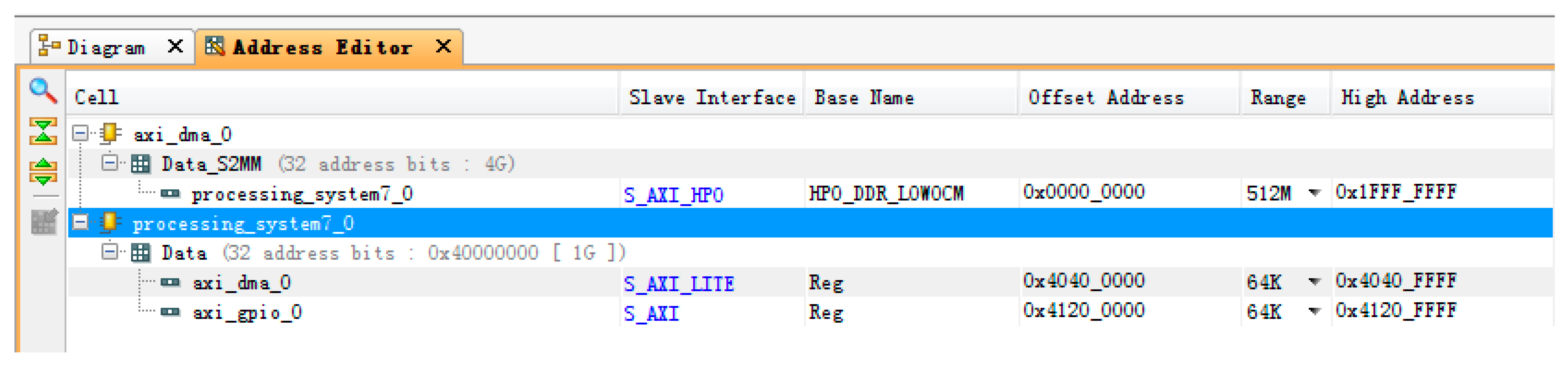
3.4.2. Communication between PL (Progarmmable Logic) and PS (Processing System)
4. Results
4.1. Face Recognition
- Construct a data matrix D;
- Find a mean face (like Figure 10);
- Reduce the dimension of the data matrix.
- 4.
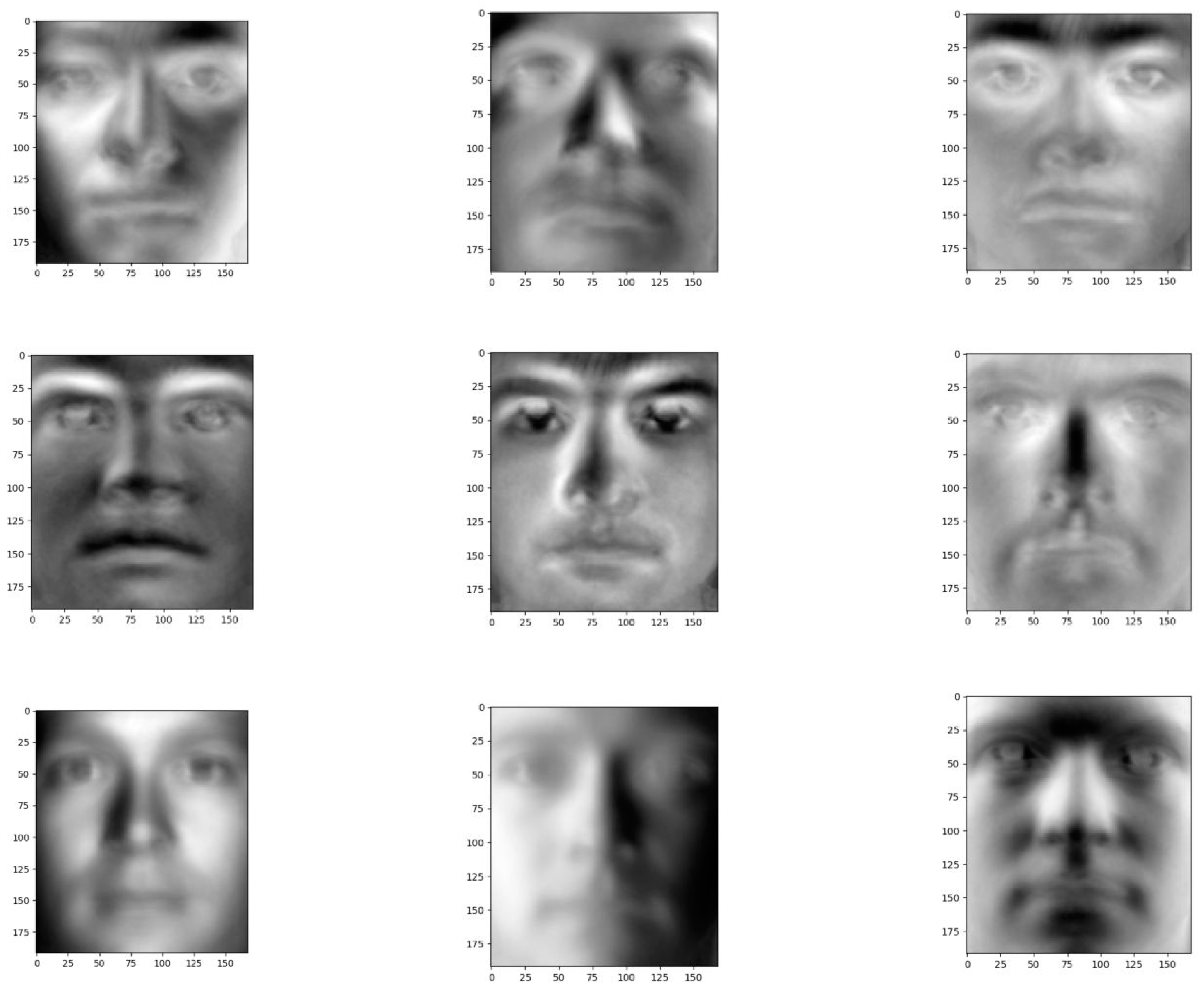
- Analyze the obtained matrix using principal component analysis to identify the featured face.
- ●
- Data matrix structure.
- Load the dataset in grayscale format;
- Convert each image into vector format;
- These vector horizontal stacked into a matrix D, if the width and height of each image W and H, respectively, the total number of images for N, is the size of the D for N * (W * H);
- Each data point is labeled as the person’s identity, which is stored in an N-dimensional vector Y.
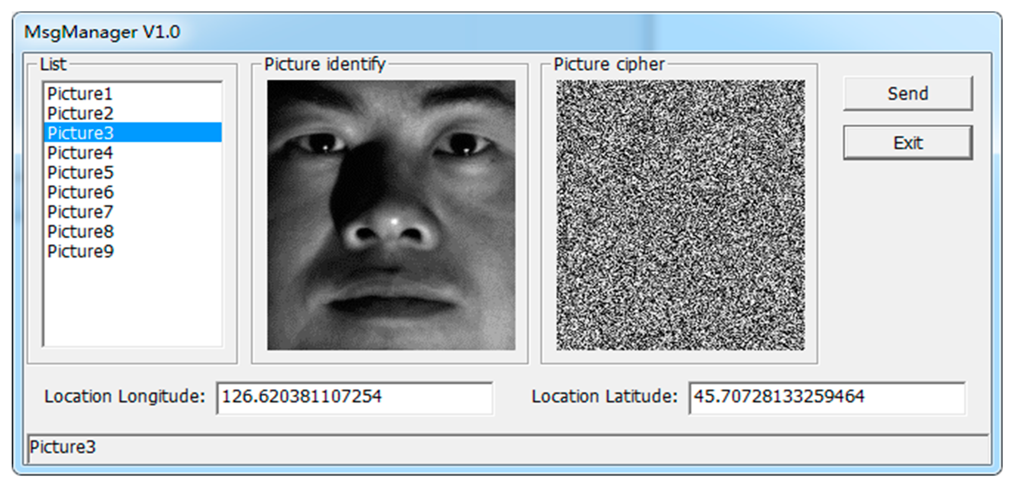
4.2. Encryption Transmission
5. Conclusions and Future Work
- The construction of a classifier using characteristic faces to achieve face recognition;
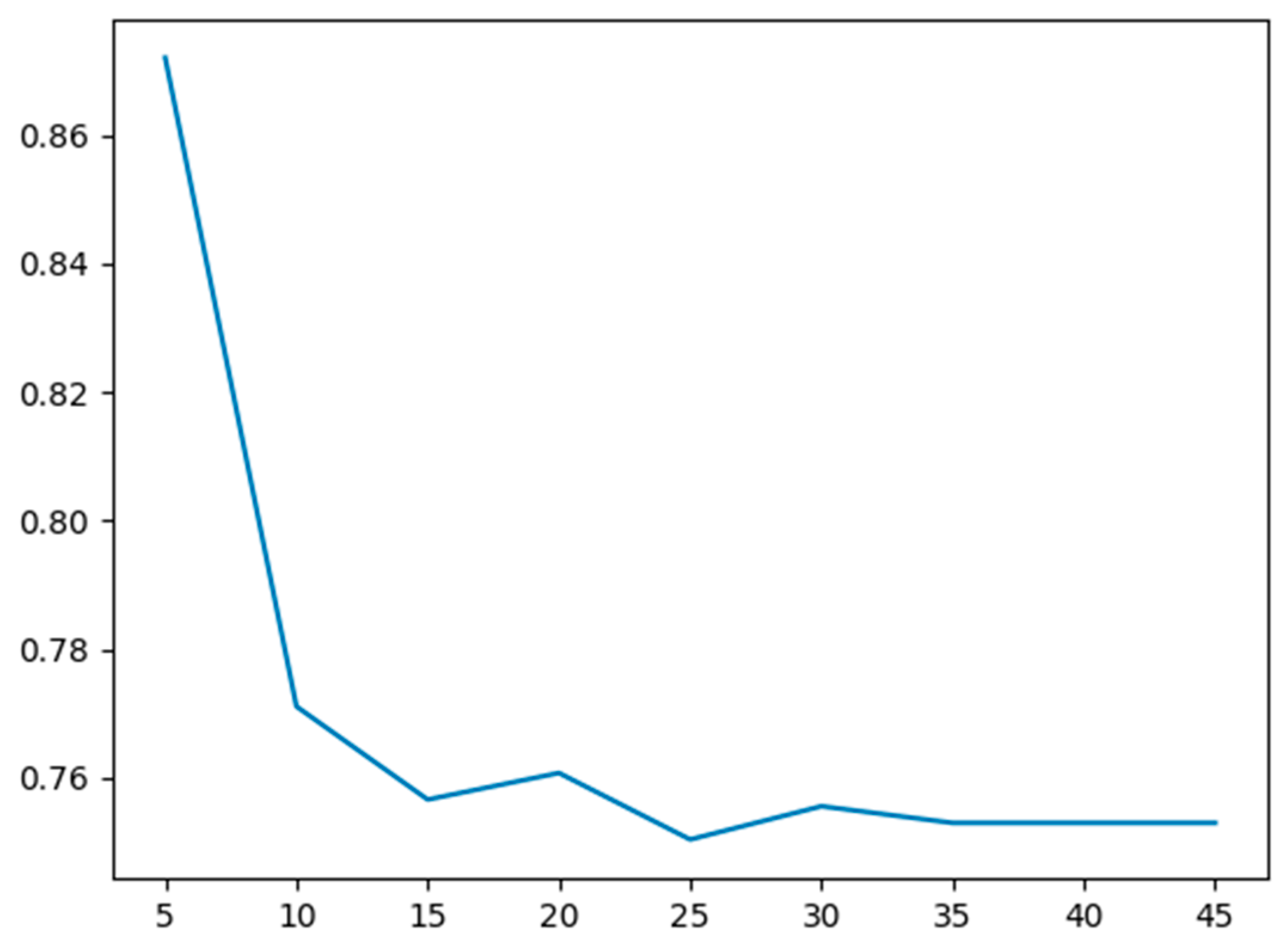
- The maximum depth hyperparameter versus the cross-validation error is plotted to find the optimal hyperparameter;
- The parameters are obtained through a 2D hyperparameter search. Clearly, the 2D hyperparameter search helped improve test error compared to the 1D hyperparameter search for maximum tree depth;
- Hardware implementation of each module design of the encryption transmission system. On the FPGA-side, the PCIe interface is developed based on XDMA. The hardware is realized, and high-speed data transmission between host and board is completed. In the SM4 encryption core module, the control module implements protocol parsing and storage, while the function module implements key expansion, encryption, and decryption, and encapsulates this into an IP core with an AXI interface, naming it in the system. Under the ARM processor environment, the DMA data communication between the PL-end and PS-end is realized, and the MAC network control module is used to realize data transmission;
- Hardware testing is carried out on the sensitive information recognition and encryption transmission system. Firstly, the system test hardware platform was built, and then the function and performance of the PCIe interface were tested and analyzed.
- Although the decision tree is used to realize face recognition, the algorithm is rarely improved, and the recognition accuracy needs to be improved;
- In the future, we will create and train our own datasets and realize real-time face recognition on video frames;
- The implementation scheme of the SM4 encryption algorithm can be improved by converting it into an assembly line design; this will increase the total resource consumption of the design, and improve the running speed of the design and the efficiency of the system implementation;
- When PCIe transfers data, it can use PIO to transfer the key and DMA to transfer the data according to the address; this no longer requires the design of a frame head resolution module, which improves the usability and scalability of the design;
- In the future, we will use FPGAs to implement public key encryption algorithms to complete digital signatures, key exchanges, etc. These modules will be combined with our existing SM4 IP.
Author Contributions
Funding
Conflicts of Interest
References
- Wei, H.; Cui, H.; Lu, X. Differential algebraic analysis of the SMS4 block cipher algorithm. J. Chengdu Univ. (Nat. Sci. Ed.) 2012, 31, 158–160. [Google Scholar]
- Cai, Y.; Qu, Y. Research and design of SMS4 encryption chip based on single-wheel loop structure. Electron. Des. Eng. 2016, 39–42, 46. [Google Scholar]
- Wang, Z.; Gao, Q. Design of DMA controller based on the FPGA PCIe bus interface. Electron. Technol. Appl. 2008, 44, 9–12. [Google Scholar]
- Li, L.; Liu, B.; Wang, H. QTL: A new ultra-lightweight block cipher. Microprocess. Microsyst. 2016, 45, 45–55. [Google Scholar] [CrossRef]
- Martínez-Herrera, A.; Mancillas-López, C.; Mex-Perera, C. GCM implementations of Camellia-128 and SMS4 by optimizing the polynomial multiplier. Microprocess. Microsyst. 2016, 45, 129–140. [Google Scholar] [CrossRef]
- Wu, J. Research and implementation of mixed cryptography algorithm based on SM4 and SM2. Softw. Guide 2013, 12, 127–130. [Google Scholar]
- Lang, H.; Zhang, L.; Wu, W. Fast software implementation technology of SM4. J. Univ. Chin. Acad. Sci. 2008, 35, 180–187. [Google Scholar]
- Wang, Y. Research on the hardware implementation of SMS4 cryptography. Autom. Instrum. 2015, 133, 137. [Google Scholar]
- Legat, U.; Biasizzo, A.; Novak, F. A compact AES core with on-line error-detection for FPGA applications with modest hardware resources. Microprocess. Microsyst. 2011, 35, 405–416. [Google Scholar] [CrossRef]
- Wei, Y. Design of PCIe Bus DMA Platform Based on FPGA; Wuhan University of Technology: Wuhan, China, 2013. [Google Scholar]
- Mohd, B.; Hayajneh, T.; Vasilakos, A. A survey on lightweight block ciphers for low-resource devices: Comparative study and open issues. J. Netw. Comput. Appl. 2015, 58, 73–93. [Google Scholar] [CrossRef]
- Magerman, D.M. Statistical decision-tree models for parsing. In Proceedings of the 33rd Annual Meeting on Association for Computational Linguistics, Cambridge, MA, USA, 26–30 June 1995; pp. 276–283. [Google Scholar]
- Freund, Y.; Mason, L. The alternating decision tree learning algorithm. Icml 1999, 99, 124–133. [Google Scholar]
- Polat, K.; Güneş, S. Classification of epileptiform EEG using a hybrid system based on decision tree classifier and fast Fourier transform. Appl. Math. Comput. 2007, 187, 1017–1026. [Google Scholar] [CrossRef]
- Tso, G.K.F.; Yau, K.K.W. Predicting electricity energy consumption: A comparison of regression analysis, decision tree and neural networks. Energy 2007, 32, 1761–1768. [Google Scholar] [CrossRef]
- Mulay, S.A.; Devale, P.R.; Garje, G.V. Intrusion detection system using support vector machine and decision tree. Int. J. Comput. Appl. 2010, 3, 40–43. [Google Scholar] [CrossRef]
- Pal, M.; Mather, P.M. An assessment of the effectiveness of decision tree methods for land cover classification. Remote Sens. Environ. 2003, 86, 554–565. [Google Scholar] [CrossRef]
- Sahinoglu, M. Security meter: A practical decision-tree model to quantify risk. IEEE Secur. Priv. 2005, 3, 18–24. [Google Scholar] [CrossRef]


| Precision | Recall | F1-Score | Support | |
|---|---|---|---|---|
| YaleB02 | 0.92 | 0.72 | 0.81 | 50 |
| YaleB03 | 0.89 | 0.91 | 0.90 | 65 |
| YaleB05 | 0.87 | 0.63 | 0.73 | 46 |
| Average/total | 0.89 | 0.75 | 0.81 | 161 |
| Encryption Card Type | Clock | Speed |
|---|---|---|
| PCI encryption card | 100 MHz | 80 MB/s |
| PCIe encryption card (BL DMA) | 100 MHz | 500 MB/s |
| PCIe encryption card (SG DMA) | 100 MHz | 1 GB/s |
© 2020 by the authors. Licensee MDPI, Basel, Switzerland. This article is an open access article distributed under the terms and conditions of the Creative Commons Attribution (CC BY) license (http://creativecommons.org/licenses/by/4.0/).
Share and Cite
Liu, S.; Yang, Z.; Li, Y.; Wang, S. Decision Tree-Based Sensitive Information Identification and Encrypted Transmission System. Entropy 2020, 22, 192. https://doi.org/10.3390/e22020192
Liu S, Yang Z, Li Y, Wang S. Decision Tree-Based Sensitive Information Identification and Encrypted Transmission System. Entropy. 2020; 22(2):192. https://doi.org/10.3390/e22020192
Chicago/Turabian StyleLiu, Shuang, Ziheng Yang, Yi Li, and Shuiqing Wang. 2020. "Decision Tree-Based Sensitive Information Identification and Encrypted Transmission System" Entropy 22, no. 2: 192. https://doi.org/10.3390/e22020192