
Energy and Entropy Production of Nanofluid within an Annulus Partly Saturated by a Porous Region


Abstract
:1. Introduction
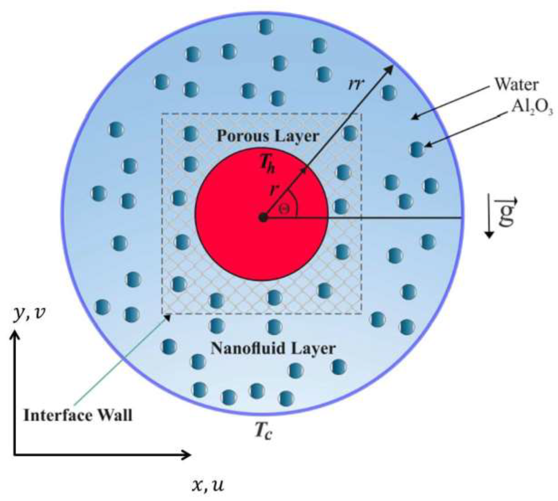
2. Mathematical Formulation
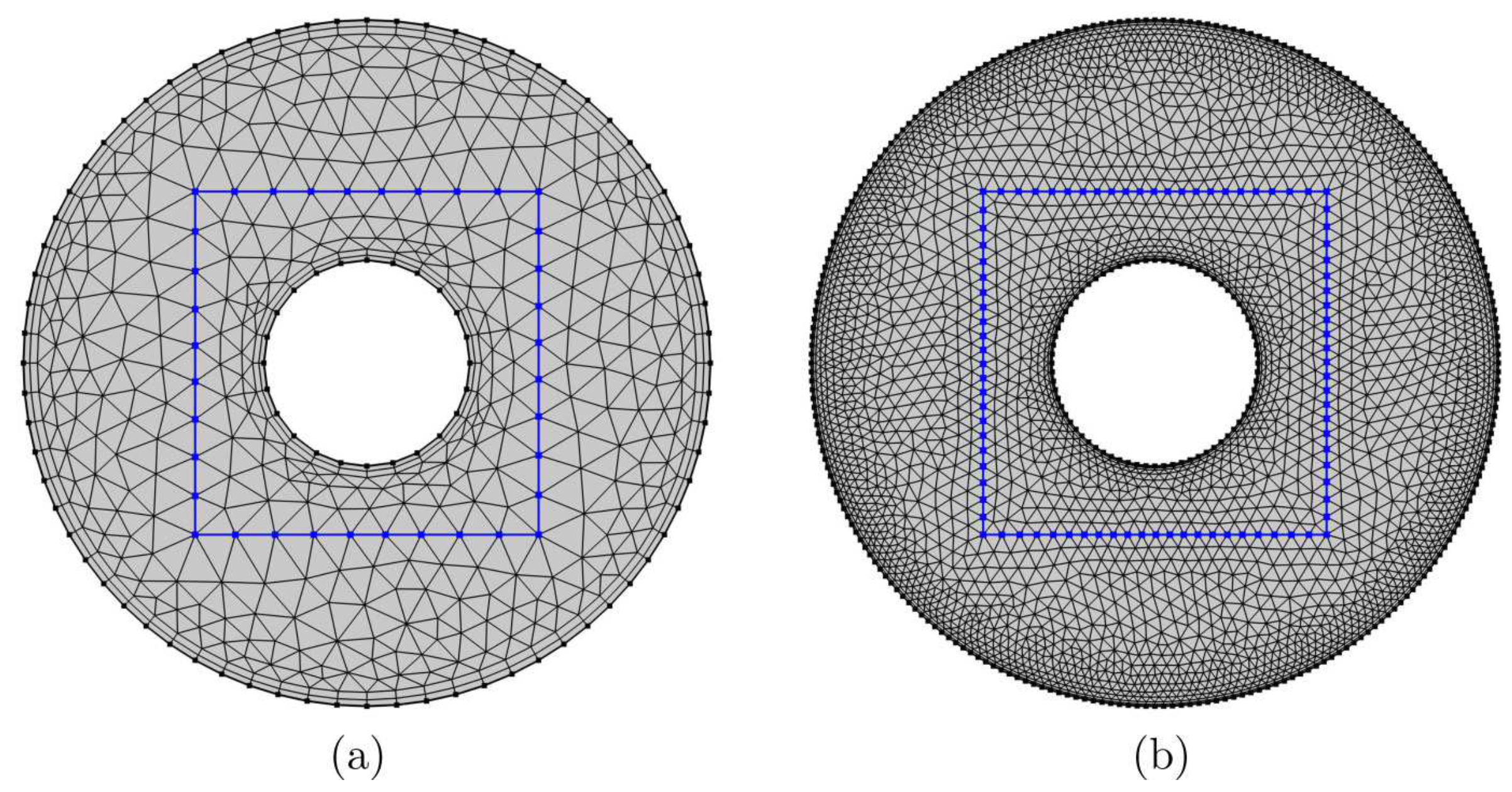
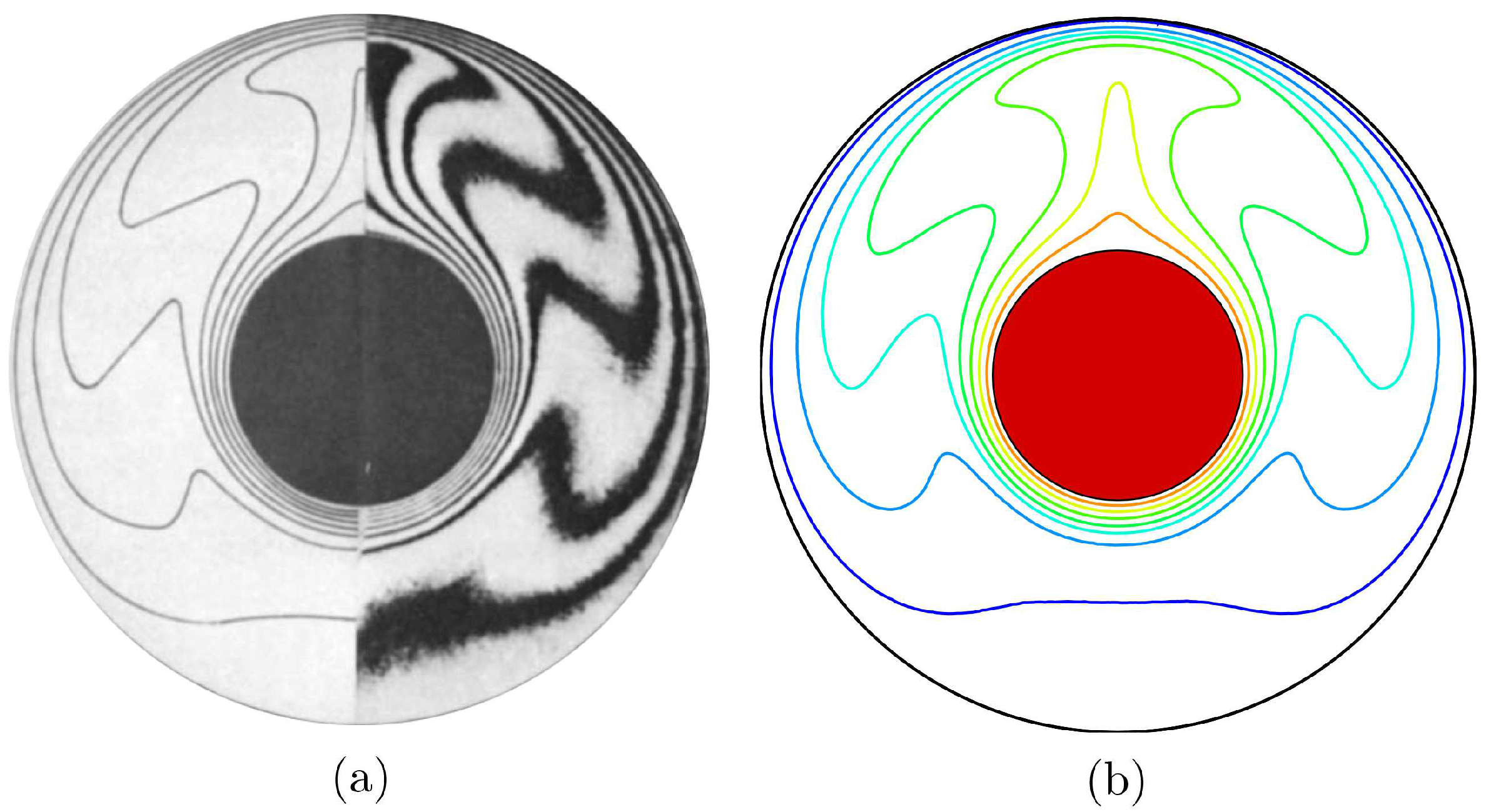
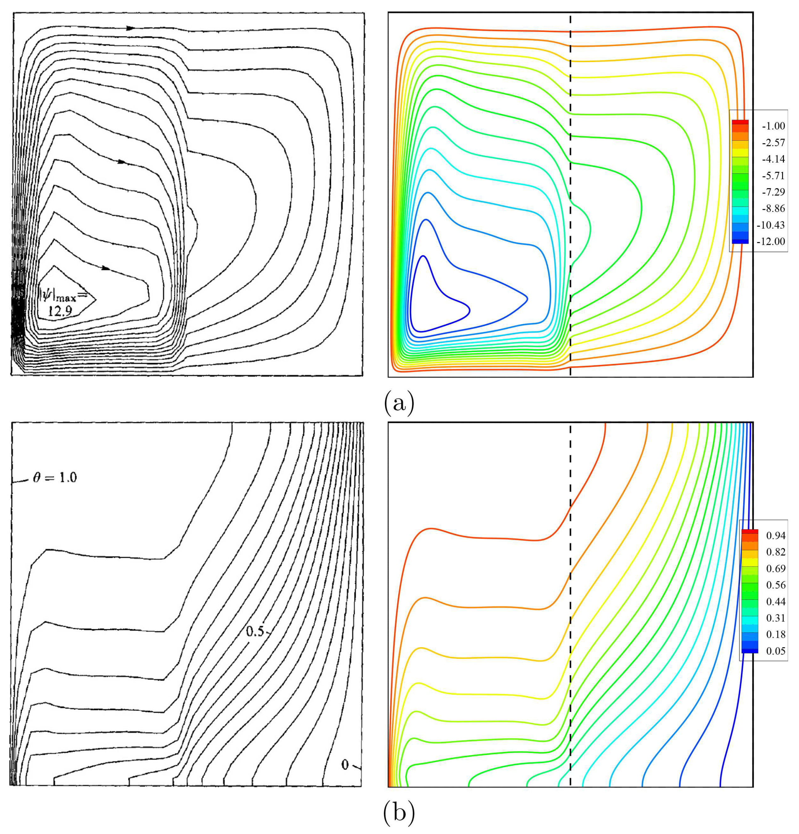
3. Numerical Method and Validation
4. Results and Discussion
5. Conclusions
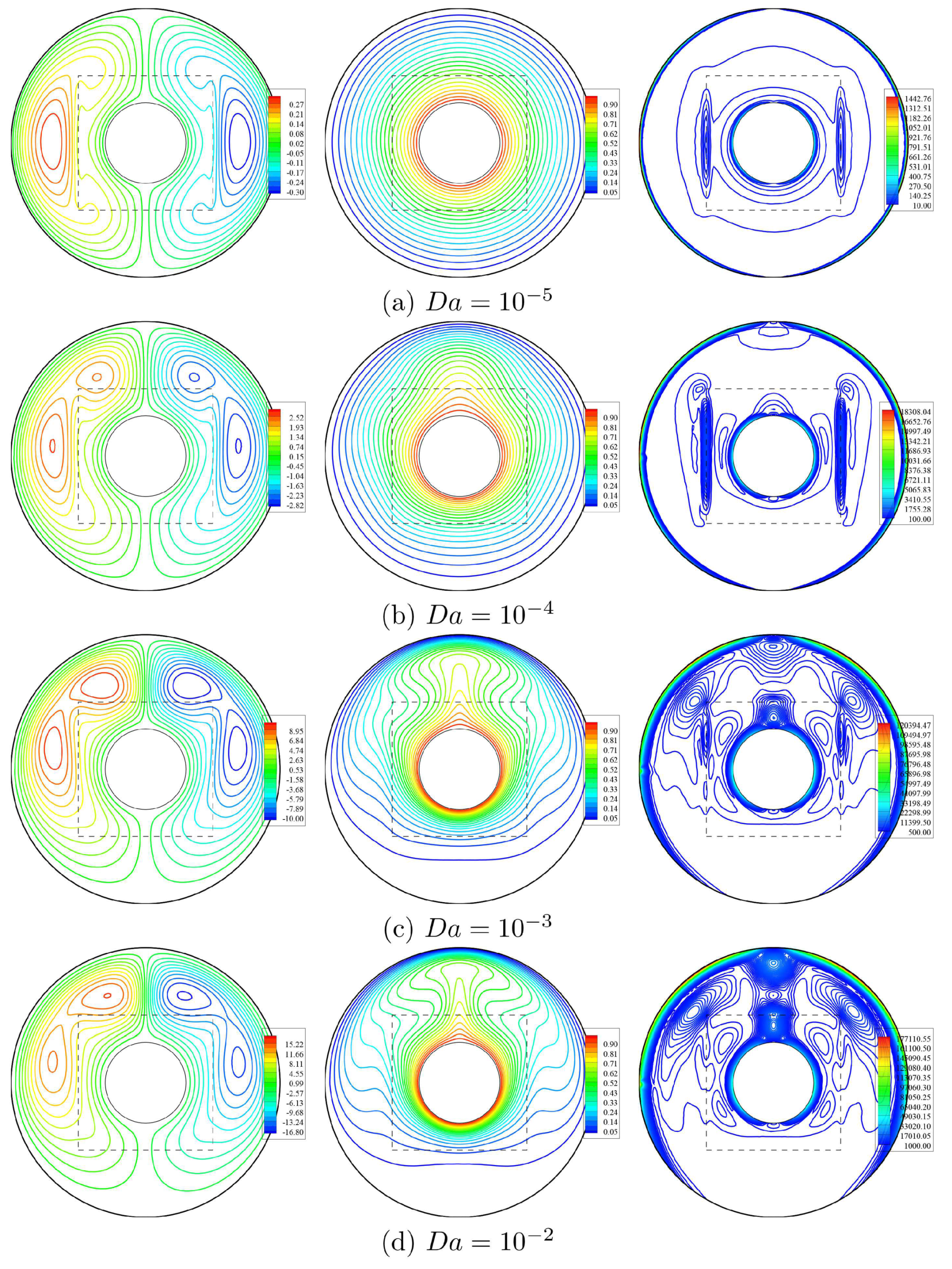
- Increasing the Darcy parameter from to powers the value of streamlines’ maximum and strengthens the intensity of the isotherms and isentropic lines within an annulus due to higher porous resistance at a lower Darcy parameter.
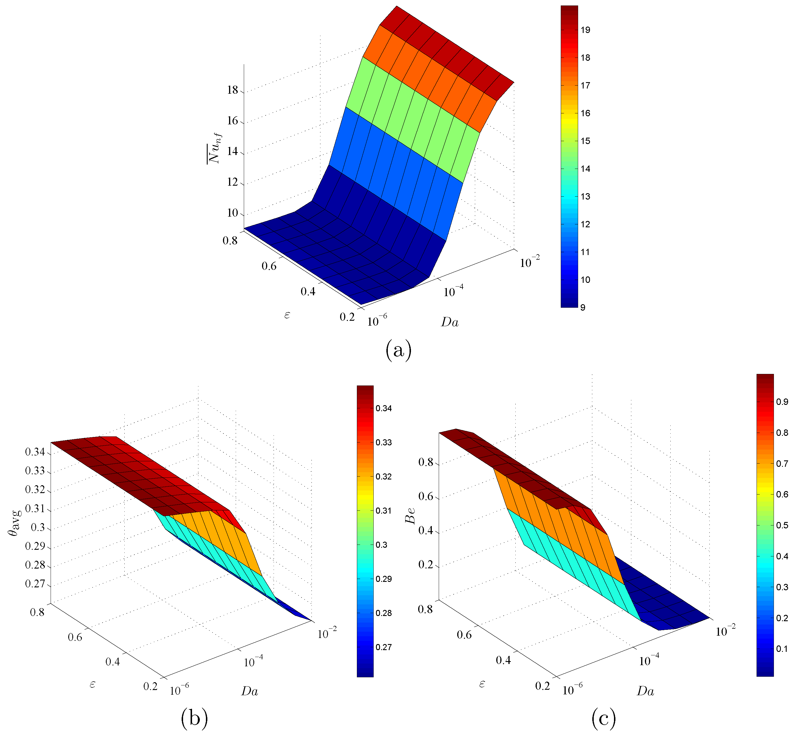
- An augmentation in the Darcy parameter boosts the local velocity and average Nusselt number and reduces the average temperature and Bejan number.
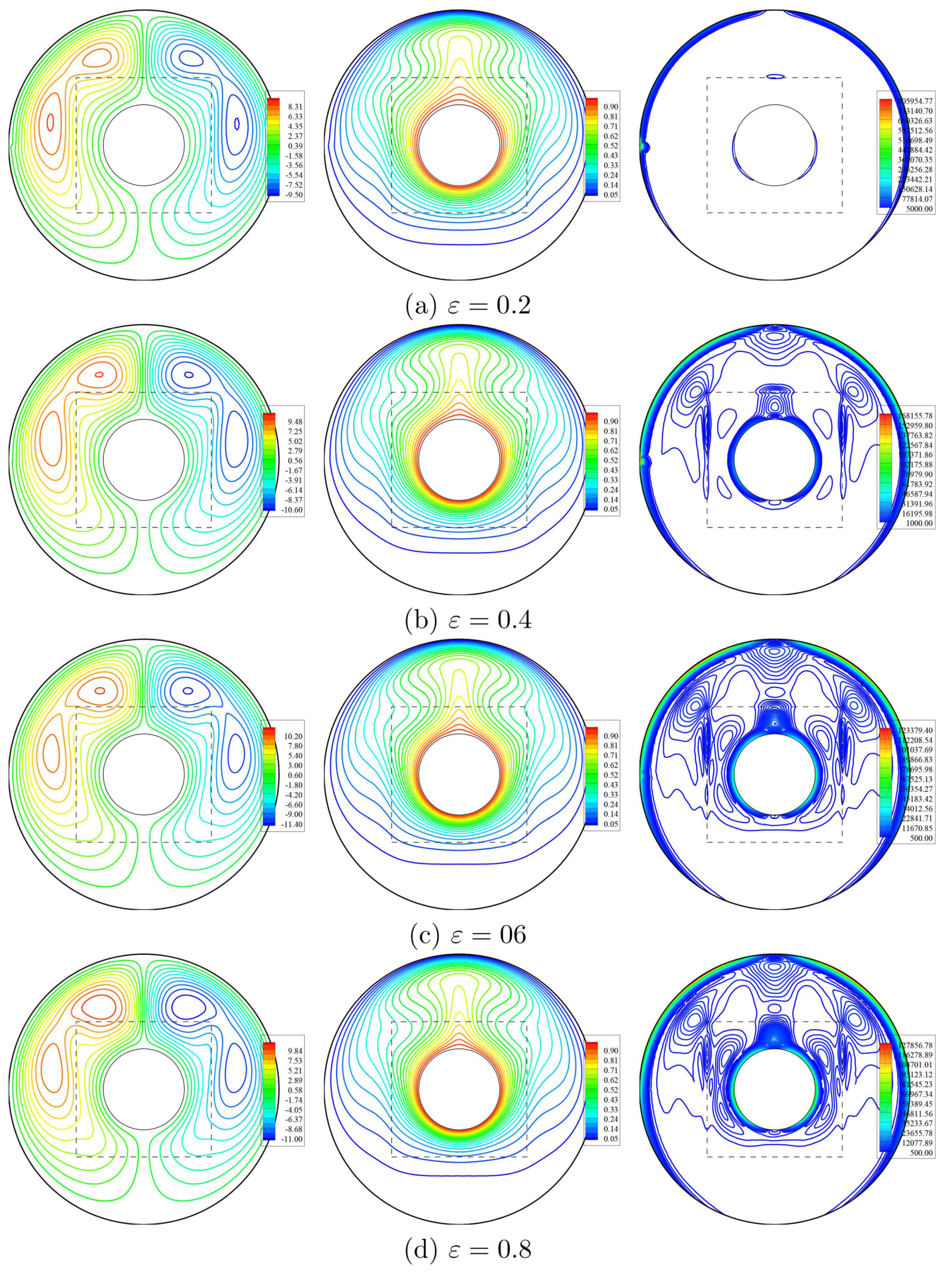
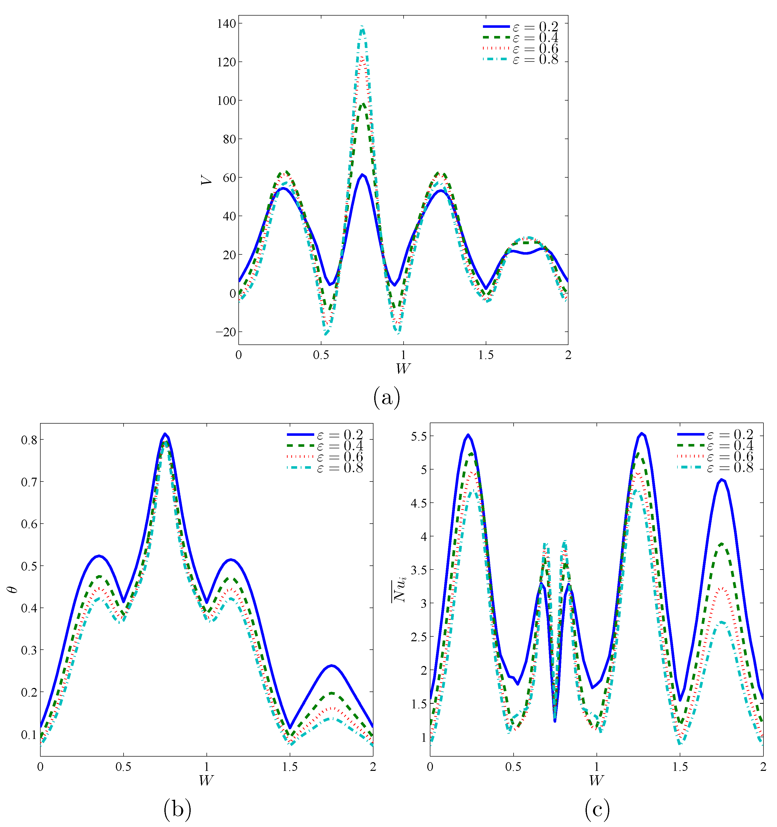
- Increasing the porosity parameter augments the streamlines’ maximum by 32.37% and improves the contours of isentropic lines within an annulus.
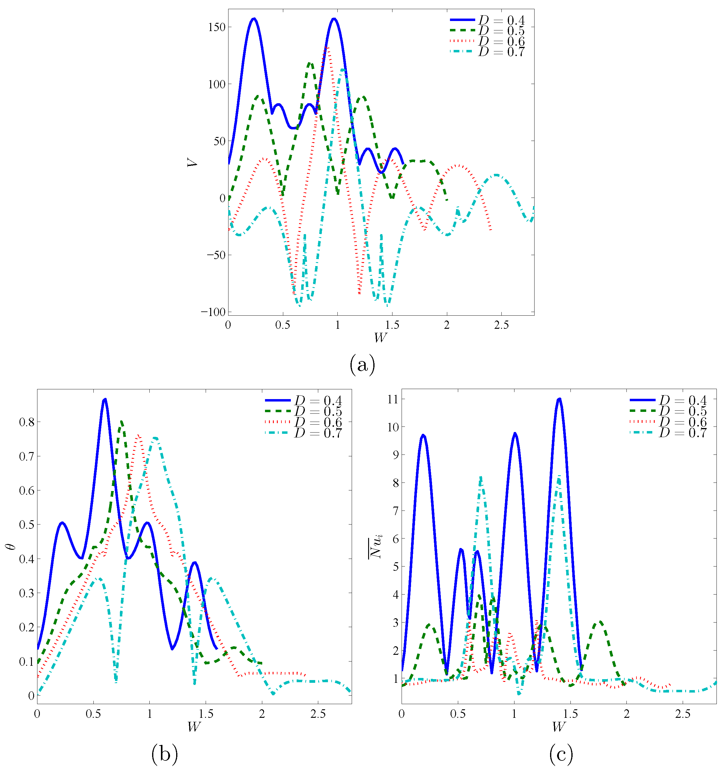
- The value of streamlines’ maximum reduces by 25% as the length of a porous layer raises from 0.4 to 0.7.
- The highest values of the local velocity and local temperature correspond with lower lengths of a porous layer.
- The profiles of the local Nusselt number decrease according to an increase in the length of a porous layer.
- Increasing the solid volume fraction improves the values of the average Nusselt number and reduces the average temperature and Bejan number.
Author Contributions
Funding
Institutional Review Board Statement
Informed Consent Statement
Acknowledgments
Conflicts of Interest
Nomenclature
| Bejan number | |
| specific heat capacity (J/kg K) | |
| Darcy number | |
| g | gravitational acceleration, (m/s) |
| dimensionless global entropy generation | |
| D | dimensionless length of the porous layer, |
| k | thermal conductivity, (W/m K) |
| K | permeability of porous medium, (m) |
| N | Avogadro number |
| irreversibility distribution ratio related to the porous layer | |
| irreversibility distribution ratio related to the nanofluid layer | |
| average Nusselt number | |
| Pr | Prandtl number |
| r and | radius of inner and outer cylinders, (m) |
| Rayleigh number | |
| entropy generation rate, (J/K) | |
| dimensionless entropy generation rate | |
| dimensionless entropy generation due to heat transfer irreversibility | |
| dimensionless entropy generation nanofluid friction irreversibility | |
| Brownian motion Reynolds number | |
| T | temperature, (K) |
| reference temperature (310 K) | |
| freezing point of the base fluid (273.15 K) | |
| and | velocity components, (m/s), and dimensionless velocity components |
| Brownian velocity of the nanoparticle | |
| x, y and X, Y | space coordinates, (m), and dimensionless space coordinates |
| Greek symbols | |
| thermal diffusivity, (m) | |
| thermal expansion coefficient, (1/K) | |
| normalized temperature parameter | |
| dimensionless temperature | |
| dimensionless length of the surface of the cylinder | |
| dynamic viscosity, (m/s) | |
| kinematic viscosity, (m/s) | |
| density, (kg/m) | |
| solid volume fraction | |
| Subscript | |
| c | cold |
| f | base fluid |
| h | hot |
| m | porous layer |
| nanofluid layer | |
| p | solid nanoparticles |
| i | interface wall |
References
- Culham, J.R.; Teertstra, P.; Yovanovich, M.M. Natural convection modeling of heat sinks using web-based tools. Electron. Cool. 2000, 6, 44–51. [Google Scholar]
- Buchberg, H.; Catton, I.; Edwards, D.K. Natural convection in enclosed spaces–a review of application to solar energy collection. J. Heat Transf. 1976, 98, 182–188. [Google Scholar] [CrossRef]
- Chen, H.T.; Chou, J.C. Investigation of natural-convection heat transfer coefficient on a vertical square fin of finned-tube heat exchangers. Int. J. Heat Mass Transf. 2006, 49, 3034–3044. [Google Scholar] [CrossRef]
- Mistry, H.; Dey, S.; Bishnoi, P.; Castillo, J.L. Modeling of transient natural convection heat transfer in electric ovens. Appl. Therm. Eng. 2006, 26, 2448–2456. [Google Scholar] [CrossRef]
- Dayem, A.M.A. Experimental and numerical performance of a multi-effect condensation–evaporation solar water distillation system. Energy 2006, 31, 2710–2727. [Google Scholar]
- Kalaiselvam, S.; Veerappan, M.; Aaron, A.A.; Iniyan, S. Experimental and analytical investigation of solidification and melting characteristics of PCMs inside cylindrical encapsulation. Int. J. Therm. Sci. 2008, 47, 858–874. [Google Scholar] [CrossRef]
- Wang, S.; Faghri, A.; Bergman, T.L. A comprehensive numerical model for melting with natural convection. Int. J. Heat Mass Transf. 2010, 53, 1986–2000. [Google Scholar] [CrossRef]
- Sparrow, E.M.; Ramsey, J.W.; Kemink, R.G. Freezing controlled by natural convection. J. Heat Transf. 1979, 101, 578–584. [Google Scholar] [CrossRef]
- Sparrow, E.M.; Larson, E.D.; Ramsey, J.W. Freezing on a finned tube for either conduction-controlled or natural-convection-controlled heat transfer. Int. J. Heat Mass Transf. 1981, 24, 273–284. [Google Scholar] [CrossRef]
- Nield, D.A.; Bejan, A. Convection in Porous Media; Springer: Berlin, Germany, 2006; Volume 3. [Google Scholar]
- Toosi, M.H.; Siavashi, M. Two-phase mixture numerical simulation of natural convection of nanofluid flow in a cavity partially filled with porous media to enhance heat transfer. J. Mol. Liq. 2017, 238, 553–569. [Google Scholar] [CrossRef]
- Raizah, Z.A.S.; Aly, A.M.; Ahmed, S.E. Natural convection flow of a power-law non-Newtonian nanofluid in inclined open shallow cavities filled with porous media. Int. J. Mech. Sci. 2018, 140, 376–393. [Google Scholar] [CrossRef]
- Alsabery, A.I.; Ismael, M.A.; Chamkha, A.J.; Hashim, I. Effect of nonhomogeneous nanofluid model on transient natural convection in a non-Darcy porous cavity containing an inner solid body. Int. Commun. Heat Mass Transf. 2020, 110, 104442. [Google Scholar] [CrossRef]
- Miroshnichenko, I.V.; Sheremet, M.A.; Oztop, H.F.; Abu-Hamdeh, N. Natural convection of alumina-water nanofluid in an open cavity having multiple porous layers. Int. J. Heat Mass Transf. 2018, 125, 648–657. [Google Scholar] [CrossRef]
- Cho, C.C. Effects of porous medium and wavy surface on heat transfer and entropy generation of Cu-water nanofluid natural convection in square cavity containing partially-heated surface. Int. Commun. Heat Mass Transf. 2020, 119, 104925. [Google Scholar] [CrossRef]
- Selimefendigil, F.; Öztop, H.F. Magnetohydrodynamics forced convection of nanofluid in multi-layered U-shaped vented cavity with a porous region considering wall corrugation effects. Int. Commun. Heat Mass Transf. 2020, 113, 104551. [Google Scholar] [CrossRef]
- Mehryan, S.A.M.; Ghalambaz, M.; Chamkha, A.J.; Izadi, M. Numerical study on natural convection of Ag–MgO hybrid/water nanofluid inside a porous enclosure: A local thermal non-equilibrium model. Powder Technol. 2020, 367, 443–455. [Google Scholar] [CrossRef]
- Alsabery, A.I.; Ismael, M.A.; Chamkha, A.J.; Hashim, I.; Abulkhair, H. Unsteady flow and entropy analysis of nanofluids inside cubic porous container holding inserted body and wavy bottom wall. Int. J. Mech. Sci. 2021, 193, 106161. [Google Scholar] [CrossRef]
- Raizah, Z.A.S.; Aly, A.M.; Ahmed, S.E. Natural convection flow of a nanofluid-filled V-shaped cavity saturated with a heterogeneous porous medium: Incompressible smoothed particle hydrodynamics analysis. Ain Shams Eng. J. 2021, 12, 2033–2046. [Google Scholar] [CrossRef]
- Aly, A.M.; Raizah, Z.A.S. Incompressible smoothed particle hydrodynamics simulation of natural convection in a nanofluid-filled complex wavy porous cavity with inner solid particles. Phys. A Stat. Mech. Its Appl. 2020, 537, 122623. [Google Scholar] [CrossRef]
- Javaherdeh, K.; Karimi, H.; Khojasteh, A. Numerical study of heat transfer enhancement of non-Newtonian nanofluid in porous blocks in a channel partially. Powder Technol. 2021, 383, 270–279. [Google Scholar] [CrossRef]
- Rao, P.S.; Barman, P. Natural convection in a wavy porous cavity subjected to a partial heat source. Int. Commun. Heat Mass Transf. 2021, 120, 105007. [Google Scholar] [CrossRef]
- Wang, L.; Huang, C.; Hu, J.; Shi, B.; Chai, Z. Effects of temperature-dependent viscosity on natural convection in a porous cavity with a circular cylinder under local thermal non-equilibrium condition. Int. J. Therm. Sci. 2021, 159, 106570. [Google Scholar] [CrossRef]
- Esfe, M.H.; Barzegarian, R.; Bahiraei, M. A 3D numerical study on natural convection flow of nanofluid inside a cubical cavity equipped with porous fins using two-phase mixture model. Adv. Powder Technol. 2020, 31, 2480–2492. [Google Scholar] [CrossRef]
- Nithiarasu, P.; Seetharamu, K.N.; Sundararajan, T. Natural convective heat transfer in a fluid saturated variable porosity medium. Int. J. Heat Mass Transf. 1997, 40, 3955–3967. [Google Scholar] [CrossRef]
- Corcione, M. Empirical correlating equations for predicting the effective thermal conductivity and dynamic viscosity of nanofluids. Energy Convers. Manag. 2011, 52, 789–793. [Google Scholar] [CrossRef]
- Ilis, G.G.; Mobedi, M.; Sunden, B. Effect of aspect ratio on entropy generation in a rectangular cavity with differentially heated vertical walls. Int. Commun. Heat Mass Transf. 2008, 35, 696–703. [Google Scholar] [CrossRef] [Green Version]
- Alsabery, A.; Ismael, M.; Chamkha, A.; Hashim, I. Numerical investigation of mixed convection and entropy generation in a wavy-walled cavity filled with nanofluid and involving a rotating cylinder. Entropy 2018, 20, 664. [Google Scholar] [CrossRef] [Green Version]
- Alsabery, A.I.; Hashim, I.; Hajjar, A.; Ghalambaz, M.; Nadeem, S.; Saffari Pour, M. Entropy generation and natural convection flow of hybrid nanofluids in a partially divided wavy cavity including solid blocks. Energies 2020, 13, 2942. [Google Scholar] [CrossRef]
- Bejan, A. Second-law analysis in heat transfer and thermal design. Adv. Heat Transf. 1982, 15, 1–58. [Google Scholar]
- Kuehn, T.H.; Goldstein, R.J. An experimental and theoretical study of natural convection in the annulus between horizontal concentric cylinders. J. Fluid Mech. 1976, 74, 695–719. [Google Scholar] [CrossRef]
- Beckermann, C.; Viskanta, R.; Ramadhyani, S. Natural convection in vertical enclosures containing simultaneously fluid and porous layers. J. Fluid Mech. 1988, 186, 257–284. [Google Scholar] [CrossRef] [Green Version]
- Bergman, T.L.; Incropera, F.P. Introduction to Heat Transfer, 6th ed.; Wiley: New York, NY, USA, 2011. [Google Scholar]


| Grid Size | Number of Elements | |||
|---|---|---|---|---|
| G1 | 486 | 19.519 | 0.30926 | 0.011058 |
| G2 | 958 | 19.525 | 0.29652 | 0.012067 |
| G3 | 1310 | 19.533 | 0.29534 | 0.016238 |
| G4 | 2008 | 19.539 | 0.29143 | 0.01726 |
| G5 | 6026 | 19.539 | 0.28799 | 0.018096 |
| G6 | 17324 | 19.543 | 0.28742 | 0.018244 |
| Physical Properties | Fluid Phase (Water) | AlO |
|---|---|---|
| 4178 | 765 | |
| 993 | 3970 | |
| 0.628 | 40 | |
| 36.2 | 0.85 | |
| 695 | – | |
| 0.385 | 33 |
Publisher’s Note: MDPI stays neutral with regard to jurisdictional claims in published maps and institutional affiliations. |
© 2021 by the authors. Licensee MDPI, Basel, Switzerland. This article is an open access article distributed under the terms and conditions of the Creative Commons Attribution (CC BY) license (https://creativecommons.org/licenses/by/4.0/).
Share and Cite
Raizah, Z.A.S.; Alsabery, A.I.; Aly, A.M.; Hashim, I. Energy and Entropy Production of Nanofluid within an Annulus Partly Saturated by a Porous Region. Entropy 2021, 23, 1237. https://doi.org/10.3390/e23101237
Raizah ZAS, Alsabery AI, Aly AM, Hashim I. Energy and Entropy Production of Nanofluid within an Annulus Partly Saturated by a Porous Region. Entropy. 2021; 23(10):1237. https://doi.org/10.3390/e23101237
Chicago/Turabian StyleRaizah, Zehba A. S., Ammar I. Alsabery, Abdelraheem M. Aly, and Ishak Hashim. 2021. "Energy and Entropy Production of Nanofluid within an Annulus Partly Saturated by a Porous Region" Entropy 23, no. 10: 1237. https://doi.org/10.3390/e23101237