Article

Heat Transfer and Fluid Flow Characteristics of Microchannel with Oval-Shaped Micro Pin Fins

School of Energy and Power Engineering, Northeast Electric Power University, Jilin 132012, China
*
Author to whom correspondence should be addressed.
Entropy 2021, 23(11), 1482; https://doi.org/10.3390/e23111482
Submission received: 7 October 2021 / Revised: 6 November 2021 / Accepted: 8 November 2021 / Published: 9 November 2021
(This article belongs to the Special Issue Computational Fluid Dynamics and Conjugate Heat Transfer)

Abstract

:
A novel microchannel heat sink with oval-shaped micro pin fins (MOPF) is proposed and the characteristics of fluid flow and heat transfer are studied numerically for Reynolds number (Re) ranging from 157 to 668. In order to study the influence of geometry on flow and heat transfer characteristics, three non-dimensional variables are defined, such as the fin axial length ratio (α), width ratio (β), and height ratio (γ). The thermal enhancement factor (η) is adopted as an evaluation criterion to evaluate the best comprehensive thermal-hydraulic performance of MOPF. Results indicate that the oval-shaped pin fins in the microchannel can effectively prevent the rise of heat surface temperature along the flow direction, which improves the temperature distribution uniformity. In addition, results show that for the studied Reynolds number range and microchannel geometries in this paper, the thermal enhancement factor η increases firstly and then decreases with the increase of α and β. In addition, except for Re = 157, η decreases first and then increases with the increase of the fin height ratio γ. The thermal enhancement factor for MOPF with α = 4, β = 0.3, and γ = 0.5 achieves 1.56 at Re = 668. The results can provide a theoretical basis for the design of a microchannel heat exchanger.

1. Introduction

With the increasing advanced technology in energy, electronics, aerospace, medicine, chemical industry, and other fields, the corresponding equipment also gradually develop in the direction of high-power, high performance, and miniaturization, such as large solid laser array, high-power LED lighting equipment, high integration microelectronics devices, etc. These electronic devices usually have a small heat transfer surface but a high-heat flux rate [1,2]. This fact leads to high operating temperatures, which can significantly reduce the reliability of components and shorten their life. Therefore, it is necessary to develop new technologies that will be able to dissipate high heat fluxes.
Several heat dissipation methods, such as microchannel heat sink, micro refrigerator, micro heat pipe, and other micro-jet array [3], have been applied to solve the problem of thermal management. Among them, microchannel heat sink (MCHS) has been widely concerned because of its larger heat transfer area, better heat transfer performance, and easy packing. However, because of the increasing heat generation per unit volume of next generation electronic devices, traditional MCHS with simple structure can hardly meet the heat dissipation requirements. Therefore, it becomes particularly important to design more effective MCHS with stronger heat dissipation capability [4].
In the past two decades, a lot of investigations in improving the heat transfer performance of MCHS were published. The influence of the cross-sectional shape of the MCHSs on the flow and heat transfer performance, such as circular, triangular, and trapezoidal, have been studied by many researchers [5,6]. Subsequently, researchers devoted to investigate various techniques to promote heat transfer performance further. The influence of MCHS flow passage, such as wavy [7,8], zig-zag [9] and convergent-divergent [10], on the characteristics of flow and heat transfer have been studied by some authors. Moreover, the flow disruption techniques have been introduced to improve the thermal performance of MCHS, for example, ribs and groove structures [11,12,13], reentrant cavities [14], roughness surfaces [15], and MCHS combined with secondary oblique channels [16,17]. In addition, nanofluids have opened the doors towards the enhancement of microchannel thermal applications performance [18]. He and Yan [19] wrote a comprehensive review to describe the various heat transfer enhancement methods in a microchannel.
In addition to all that, it has been confirmed that inclusion of pin fin in micro heat sinks can significantly increase the overall heat transfer effectiveness. Vasilev et al. [20] compared the heat transfer performance of MCHS without pin fins and MCHS with cylindrical pin fins by computational simulation. Different structure sizes of pin fins, such as diameter, spacing, and height, in MCHSs were performed, and the results showed that the fluid disturbance was increased because of the placing of pin fins in the flow channels, which enhance the thermal performance of MCHS. For the purpose of improving the temperature uniformity of the cooled device, a micro-pin-fin heat sink with variable density was proposed by Vilarrubí et al. [21]. The results showed that the convection thermal resistance was decreased and the better surface temperature uniform was displayed by using increasing density of pin-fins along the flow direction. Prajapati et al. [22] studied numerically the heat transfer and fluid flow behavior of rectangular parallel microchannel heat sinks with varying fin heights. It has been observed that pen microchannel heat sinks have a greater advantage than the completely closed heat sink. Ventola et al. [23] proposed a diamond-shaped micro-protruded patterns heat sink and experimentally investigated the thermal fluid dynamics features. The geometrical parameters of diamond shaped fins were also studied and optimized, which revealed to have a significant influence on convective heat transfer. Wang et al. [24] proposed an optimal origami fin shape to enhance the forced and free convection heat transfer of the heat sink.
From the abovementioned review, it can be illustrated that the micro pin fin within the heat sink can obviously improve the thermal performance of cooling devices. Meanwhile, the heat transfer and pressure drop are directly dependent on the pin fin’s shape and their positions within the heat sink. In our preliminary work, a microchannel combined with cone-shaped micro pin fins (MCPF) was proposed, and the heat transfer and fluid flow characteristics of MCPF were numerically investigated. The geometric sizes optimization of MCPF reveals that there exist optimal fin sizes that satisfy both heat transfer and pressure drop conditions [25]. According to Stoddard’s research, which suggested that the stronger the bird flight ability, the more elongated the egg shape, which is deviated from the circular shape and closer to the streamlined shape. The elongated oval shape also reduces drag while ensuring that the egg has enough capacity, which helps the bird save more energy for flight. These conclusions were obtained by comparison of the egg shape of various birds and their flight ability [26]. Thus, in this study, oval-shaped micro pin fins are arranged in a smooth rectangular channel as a new finned microchannel, and the heat and heat transfer performance are investigated by numerical methods. Meanwhile, the influence of fin axial length ratio (α), fin width ratio (β), and fin height ratio (γ) on the flow and heat transfer performance is investigated, and the thermal enhancement factor is used to evaluate the overall performance of MOPF.

2. Model Description

A MCHS typically consists of several parallel channels, which are used to carry coolant fluid. The configuration of a typical MCHS is depicted schematically in Figure 1. The conventional rectangular microchannel is selected as a comparison. Because of the symmetry of microchannels, usually only one minimal unit of heat sink is simulated to perform the analysis, as illustrated in Figure 1b and Figure 2a. The newly proposed microchannel, which has oval-shaped micro pin fins, in a constant cross-section region in line is plotted in Figure 2. It has the same size with the corresponding rectangular microchannel except the inserted fins. Figure 2b is the top view of the channel with oval-shaped micro pin fin, which is composed of a semicircle and semi-ellipse. Rpf is the radius of the semicircle, which is also the length of a short half axis of the semi-ellipse. The length of long half axes of the semi-ellipse are denoted as Rpf,l. The height of the micro pin fin is marked as Hpf, and its value is variable. In order to investigate the effects of geometric structure on fluid flow and heat transfer, three non-dimensional variables are defined as follows: α is defined as the ratio of the long semi-axial length (Rpf,l) to the constant short semi-axial length (Rpf) of the oval-shaped micro pin fin. The fin width ratio β(β = 2Rpf/Wch) is defined as the ratio of the short axis length to the width of channel, and the fin height ratio (γ = Hpf/Hch) is defined as the ratio of fin height to the channel height. The basic geometric parameters of a single microchannel are shown in Table 1.

3. Numerical Solution and Procedures

In this study, FLUENT 18.0 software was used to carry out three-dimensional numerical simulation calculation of flow and heat transfer characteristics of microchannels, and the calculation process was assumed as follows:
(1)
The fluid flow in the channel is considered as three-dimensional steady laminar flow;
(2)
The fluid in this work is water, which can be considered as incompressible Newtonian fluid. Meanwhile, the temperature variations are in the range of 293–320 K, therefore, the viscosity variation with temperature can be assumed as linear, and other solid and fluid property parameters are assumed as constant;
(3)
The effects of gravity, volume force, surface tension, and thermal radiation are not taken into account.

3.1. Governing Equations

According to the above assumptions, the governing equations of the model are simplified as follows:
Mass equation:
u x + v y + w z = 0
Momentum equation:
u u x + v u y + w u z = 1 ρ f p x + μ f ρ f 2 u x 2 + 2 u y 2 + 2 u z 2
u v x + v v y + w v z = 1 ρ f p y + μ f ρ f 2 v x 2 + 2 v y 2 + 2 v z 2
u w x + v w y + w w z = 1 ρ f p z + μ f ρ f 2 w x 2 + 2 w y 2 + 2 w z 2
Energy equation (for the fluid):
u T f x + v T f y + w T f z = k f ρ f c pf 2 T f x 2 + 2 T f y 2 + 2 T f z 2
Energy equation (for the substrate conduction):
0 = k s 2 T s x 2 + 2 T s y 2 + 2 T s z 2
where u, v, and w are respectively the velocity component in the x, y, and z directions; ρf, μf, cpf, kf, and ks are density, dynamic viscosity, specific heat capacity, and thermal conductivity of liquid and solid, respectively. P, Tf, and Ts are the pressure and temperature of liquid and solid, respectively.

3.2. Boundary Conditions

(1) The channel inlet is set as the velocity inlet boundary condition, and the fluid inlet temperature is constant at 293 K;
x = 0 , u f = u in ; T f = T in = 293 K
(2) At the channel outlet, the pressure-outlet boundary is applied;
x = L , P f = P out = 0
(3) The solid walls coupled with fluid are set as the coupled boundary condition, and the no-slip condition boundary is applied on the fluid–solid interface.
k s T s n w = k s T f n , u = v = w = 0
(4) The symmetry condition is used in two side walls of the microchannel;
T s y = 0 ,   ( y = 0 ,   y = 0.15   mm )
(5) The bottom surface of the microchannel is set as the uniform heat flux boundary, and the top surface of the channel is adiabatic;
z = 0 , q = 10 6 W / m 2 ; z = H , T n w = 0
The governing equations are solved using the finite volume-based computational fluid dynamics solver FLUENT. The SIMPLEC algorithm (p-v coupling) is applied to solve the governing equations. Second order discretization scheme is adopted for the pressure equation, and second-order upwind scheme is employed for discretization of momentum and energy equations. The residual criteria of continuity equation and velocity are set as 10−6 and that of energy equation is 10−7.

3.3. Data Reduction

The inlet Reynolds number is defined as:
R e = ρ u in D h μ
where uin is the channel inlet velocity, ρ is the water density, and Dh is the hydraulic diameter of the microchannel, which can be expressed as:
D h = 2 W ch H ch W ch + H ch
The apparent friction coefficient of the microchannel can be expressed as:
f app , ave = 2 Δ p D h ρ L u m 2
where Δp is the pressure drop of microchannel, L is the channel length, and um is the average velocity.
The average convective heat transfer coefficient is written as:
h ave = Q A con Δ T = q A b A con T b T f , m
And the Nusselt number of microchannels are given as follows:
N u ave = h ave D h k f
where q is the constant heat flux, Ab is the area of channel bottom wall; Tb and Tf,m are average bottom wall temperature and average fluid temperature respectively; Acon is the effective heat transfer area; and kf is fluid thermal conductivity.
In order to evaluate the overall performance of the microchannel with oval-shaped micro pin fins, the thermal enhancement factor η was introduced to measure the heat transfer enhancement against the pressure drop increment for laminar flow with chaotic advection. The bigger η is, the better the overall performance of the microchannel. The expression for η is given by [27]
η = N u ave / N u 0 f ave / f 0 1 / 3
where Nu0 and f0 are the average Nusselt number and average apparent friction coefficient of the rectangular microchannel, respectively.

3.4. Grid Independence and CFD Simulations

The ICEM meshing software was utilized to generate meshes for the solver, and the unstructured meshing method was adopted. Figure 3 shows the local grid division diagram of a microchannel with oval-shaped pin fin (α = 3, β = 0.3, γ = 1) in the x-z plane (y = 0.25 mm). The green region is the calculation domain of solid silicon, and the yellow region is the calculation domain of deionized water. For every microchannel heat sink, a grid independence test is conducted using several different mesh sizes. The average Nusselt number Nuave and pressure drop Δp were selected as parameters for grid independent verification. Meanwhile, the relative error between the finest grids (J1) and other grids (J2) is written as:
e % = J 2 J 1 J 1 × 100 %
By gradually refining the meshes, five different grid quantities (856,372 cells, 1,626,235 cells, 2,235,843 cells, 2,806,421 cells, 3,414,287 cells) were selected for verification, and the results were shown in Table 2. The relative error e% is less than 2% when the number of meshes is 2,235,843 cells. In order to reduce the computation time, 2,235,843 cell grids were selected for the subsequent simulation calculation.

4. Results and Discussion

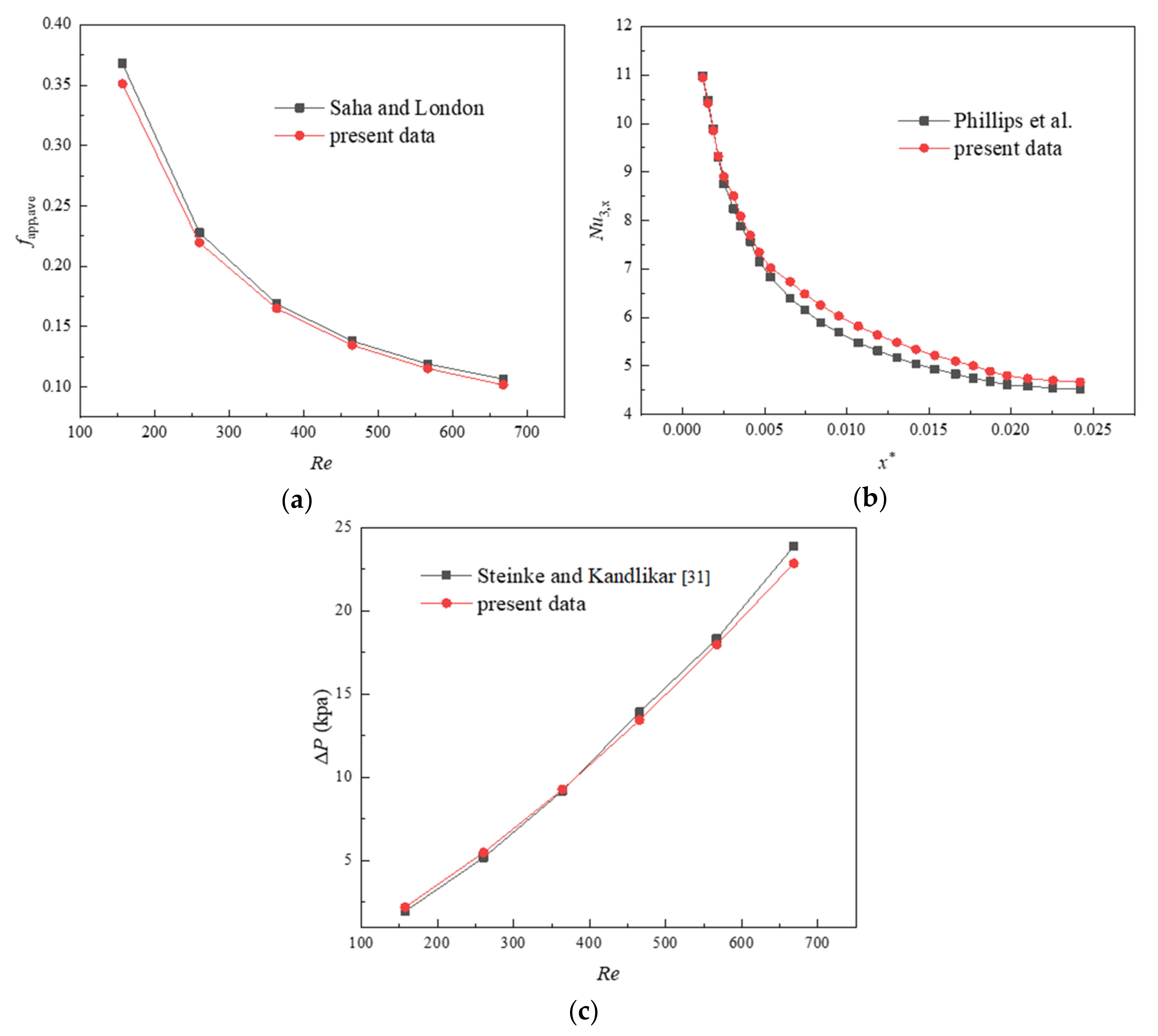
4.1. Verification of Numerical Models

It is necessary to check the accuracy and reliability of the mathematical model; numerical results of friction factor and local Nusselt number for the rectangular MCHS are compared with the theoretical solutions. The relation of apparent friction coefficient under the condition of fully developed laminar flow can be expressed as:
f = P o R e
According to the model proposed by Shah and London [28], Poiseuille number can be written as follows:
P o = 96 1 1.3553 AR + 1.9467 AR 2 1.7012 AR 3 + 0.9564 AR 4 0.2537
The relationship between apparent friction coefficient and Reynolds number and Poiseuille number is shown as follows:
f app , ave R e = 3.2 L / Re D h 2 + P o 2
where AR is the aspect ratio of the microchannel, which is 1 in this study;
The local Nusselt number of the three sides-heated microchannel is written as [29]:
N u 3 , x = N u 4 , x N u 3 , / N u 4 ,
where Nu3,∞ and Nu4,∞ represent fully developed Nusselt numbers for three-side heating and four-side heating, respectively. The local Nusselt number Nu4,x is calculated by Kandlikar model as follows [30]:
N u 4 , x = 6.7702 3.1702 x * + 0.4187 ln x * 2 + 2.1555 ln x * + 2.76 × 10 6 x * 1.5
where x is the distance to the inlet, and x* is dimensionless axial distance, which can be expressed as:
x * = x R e P r D h
P r = μ C p k
The variation of the pressure drop characteristics of the microchannel can be verified by the following formula [31]:
Δ p = 2 f R e μ u m L D h + a x ρ u m 2 2
The a(x) formula is given as follows:
a x = 0.6796 + 1.2197 AR + 3.3089 AR 2 9.5921 AR 3 + 8.9089 AR 4 2.9959 AR 5
Figure 4 shows the comparison results between the numerical calculation and the references. As can be seen from the figure, the maximum deviation of fapp,ave and Nu3,x according to the above formula are 3.8% and 4.01%, respectively. The numerical results of pressure drop are in good agreement with the theoretical data at all given Re, and deviation is within 3%. Therefore, the numerical method adopted in this paper is accurate and effective.

4.2. Thermo/Hydraulic Optimization of Fin Axial Length Ratio (α)

The relationship between f/f0 and α (=Rpf,l/Rpf) under different Re is shown in Figure 5a, of which f0 represents the average apparent friction coefficient of the rectangular microchannel. As can be seen from Figure 5a, the value of f/f0 increases obviously with the increasing of Re. Furthermore, according to calculation results, the values of f/f0 as a function of α are found to: first increase, then decrease and increase again, except for the condition of Re = 157. This phenomenon is thought to be largely determined by the combined effects of friction resistance and pressure drag. They are caused by the viscous effect, which induces the surface frictional force and flow separation and vortex shedding.
Figure 6 represents the velocity distribution along the horizontal plane (z = 0.25 mm) for MOPF with different α, and the drawings of partial enlargement are displayed at the same time. As can be seen from the figure, placing oval-shaped pin fins in flow path generates boundary layer separation and a wake region is formed in the downstream of the fin. From Figure 6b, it is easy to observe, the larger the value of α, the smaller wake region, which indicates that the pressure drag has been effectively suppressed, and this is attributed to the shape of the fins. However, due to the expansion of fin surface area, the frictional resistance inevitably increases. Thus, the total resistance of the microchannel is the result of the superposition of these two. However, when the value of α continues to increase, the increased amplitude of friction resistance is smaller than the decreased amplitude of pressure drag, perhaps as a consequence, the value of f/f0 decreases at α = 6.
The relationship between Nu/Nu0 and α (=Rpf,l/Rpf) in different Re is shown in Figure 5b, and Nu0 represents the Nusselt number of the Rec microchannel. It can be seen from Figure 5b that the value of Nu/Nu0 generally increases firstly and then decreases with the increase of α at the same Re. MOPF with α = 5 has the maximum value of Nu/Nu0 for Re ≤ 465; but MOPF with α = 4 yields the highest value of Nu/Nu0 for Re > 465. Inserting pin fins into the heat sink channel increases the heat transfer area, thus improving the convection process. On the other hand, the velocity distribution is another determining factor to convective heat transfer mechanism. Figure 6 shows the velocity distribution along the horizontal plane for MOPF with different fin axial length ratio (α) at Re = 668, and (b), (c) is the partial enlarged detail of fluid velocity at the side wall of the fins passage. It suggests that the enhanced heat transfer of the microchannel with micro pin fins is primarily attributed to flow separation, disturbance effect, and the vortexes in the mainstream rather than surface area enlargement. However, as the value of α increases, the cross-section shape of the micro pin fin on the y-z plane is closer to streamline, which causes the separation point of the boundary layer to move backward and the wake vortex region becomes smaller. Meanwhile, the impact of fluid on the wall is reduced because of the streamline fins, which leads to the weakening of the fluid disturbance. Thus, the overall heat transfer performance of the microchannel decreases for the higher value of α.
The improvement of heat transfer performance often leads to the increase of flow resistance, which certainly leads to increase the consumption of pump power. Therefore, it is necessary to comprehensively evaluate the increasement of heat transfer performance and flow resistance. According to the reasons mentioned above, the thermal enhancement factor η is introduced to compare the comprehensive performance of MOPF as shown in Equation (12). Figure 7 depicted that the value of η increases firstly and then decreases with the increase of α. The MOPF with α = 5 has the best comprehensive performance for Re ≤ 364, and the highest overall performance for Re > 364 is α = 4, and η reaches a maximum value of 1.52 when Re = 668. In addition, the value of η is affected slightly by the Re.

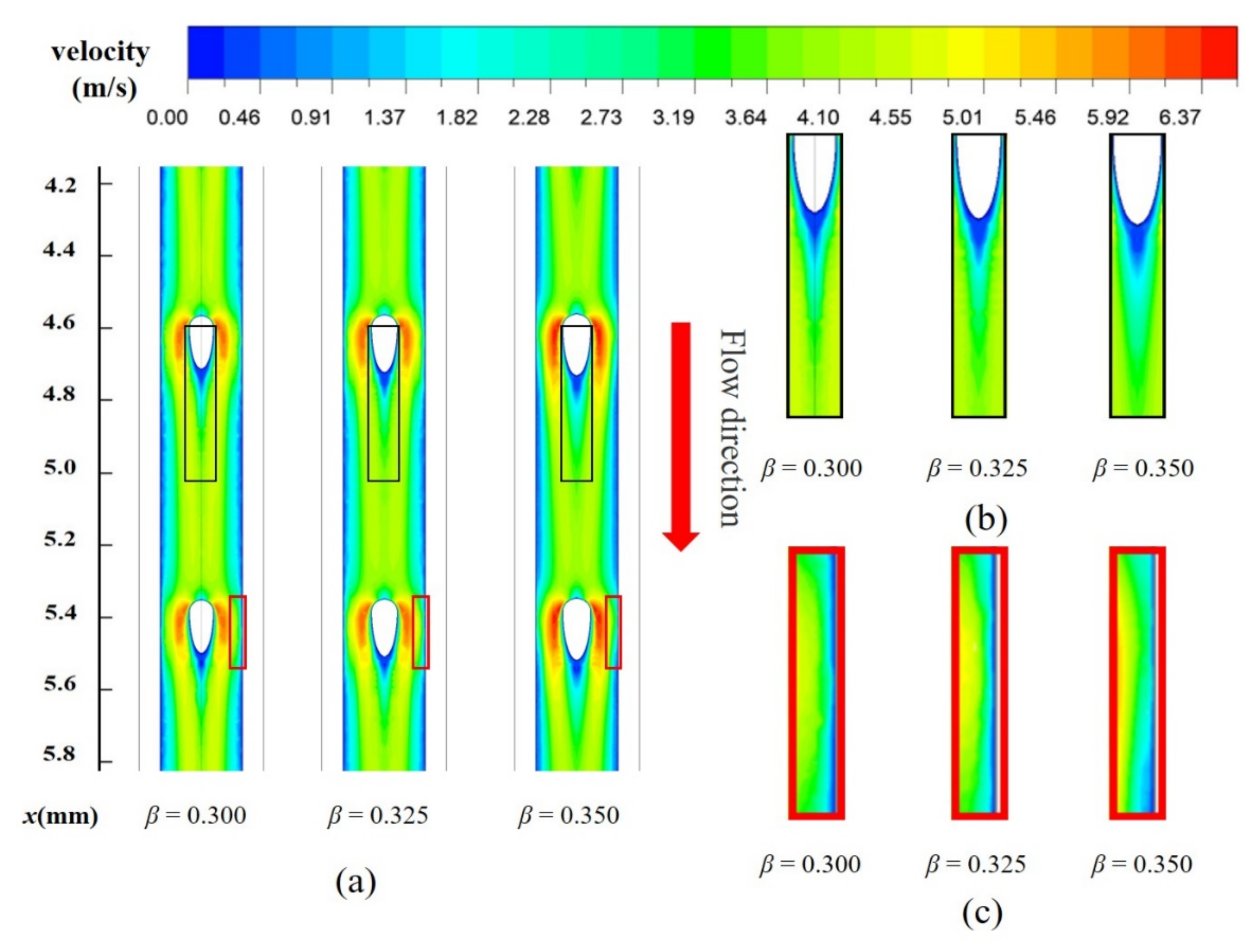
4.3. Thermo/Hydraulic Optimization of Fin width Ratio (β)

After optimizing the shape of the micro pin fin, the second design parameter, which is the fin width ratio β (=2Rpf/Wch), is also examined here. As shown in Figure 8a, f/f0 presents a gradual upward trend with the increase of the fin width ratio β in the passage, and an approximate linear increase was found over a large Reynolds number range. The reasons for this result can be explained from the following three aspects. Firstly, the blocking sections of the front of the fins increase because of the wider fin width, which results in a large blocking effect. Secondly, as the width of the fins increases, the contact area between the fluid and the solid increases, and accordingly, the friction resistance also increases. Finally, with the increase of the width of the fins, the distance between the outer side of the fins and the side wall of the channel becomes narrower, which results in a significant increase in the flow rate of fluid through these areas. The separation point of the boundary layer moves forward, and a large low-pressure circulation zone is formed at the tail of the fins, which further increases the pressure drag of fins.
In this section, the effect of fin width ratio β on heat transfer performance of MOPF is investigated. Figure 8b illustrates the Nu/Nu0 as a function of the microchannel fin width ratio β at different Re. It is noted that the Nu/Nu0 firstly increases and then decreases with the increase of the fin width ratio β. The heat transfer area increases with the increase of the fin width, and the heat transfer performance is significantly enhanced. In addition, the flow rate between the channel wall and fin increases because of the reduction of circulation area. However, as the size of fins increases, the area of trailing vortex area increases, which resulting in the heat transfer performance degradation. Figure 9 shows the velocity contours and its partial enlargement along the horizontal plane (z = 0.25 mm) for MOPF with relative fin diameter (β = 0.300~0.325) of fin at Re = 346. It is evident from the picture that the trailing vortex region becomes larger with the increase of fin diameter. Meanwhile, because of the longer fin tail, the scouring effect of the fluid on the side wall of the channel is weakened, and the boundary layer of the fluid on the side wall becomes thicker. Thus, the overall heat transfer performance is weakened.
Besides, it should not be neglected that the peak value of Nu/Nu0 corresponds to different width ratio values within different Reynolds number ranges. When Re is lower than 364, Nu/Nu0 reaches its peak value when β = 0.325, but the peak point of Nu/Nu0 moves left to β = 0.300 when Re ≥ 364. This result implies that the increase of flow velocity causes premature separation of the boundary layer at smaller fin width, which increases the wake vortex region and weakens the thermal performance.
By comparing Figure 8a,b it is found that the change of f/f0 is not always positively correlated with the change of Nu/Nu0. The former is positively correlated with β, but Nu/Nu0 shows a large decrease in the range of β = 0.325–0.350. In order to comprehensively reflect the influence of relative fin width on channel performance, the variation relationship of the η with the width ratio β at different Re is shown in Figure 10. The curve generally shows the same trend as Nu/Nu0. In the range of low Re (<346), β = 0.325 has a better comprehensive performance, but the best η in the range of high Re (>346) occurs in β = 0.300.

4.4. Thermo/Hydraulic Optimization of Fin Height Ratio (γ)

Except for the shape and size of fins, the height of the fin also has a great influence on flow and heat transfer performance of the microchannel. The height of fins not only affects the heat transfer area, but also affects the distribution of fluid velocity and increases fluid disturbance. The results of f/f0 and Nu/Nu0 for variable fin height ratio (γ = Hpf/Hch) with constant values of α = 4 and β = 0.3 are gained and described in Figure 11. As can be seen from Figure 11a, the value of f/f0 increases with the increase of Re at the same relative fin height, and it was positively correlated with the relative fin height under the same Re number condition. The change of f/f0 can be attributed to two aspects: As the height of fin increases, the shear force on the fluid–solid interface and the pressure drag increase accordingly.
Figure 11b shows the variation of Nu/Nu0 with γ under different Reynolds Numbers. The value of Nu/Nu0 increases with the increase of γ, indicating that the heat transfer performance of the channel is gradually improved by the increase of the fin height. This is the result of the combined effect of increasement of heat transfer area and fluid disturbance. The temperature distribution of axial surface (y = 0 mm) in the second half of the microchannel at Re = 567 was observed in Figure 12. The average temperature of fluid is the highest when γ = 1.0, while the average temperature of solid area is the lowest. This phenomenon is also reflected in Figure 13. It represents the distribution of temperature gradient on the heated bottom wall corresponding to different fin height at the same inlet Re. From the figure, it is worth noting that the temperature of the bottom wall decreases with the increase of the relative fin height, and the temperature is well-distributed when the relative fin height is aequal to 1. Such phenomenon is in agreement with a previous study reported by Jia et al. [24]
As stated above, in addition to the increase in thermal performance, significance also increases with pressure drop. Thus, the comprehensive performance of flow and heat transfer is necessary to obtain and compare. The variation of the thermal enhancement factor η with Re is obtained as illustrated in Figure 14. The value of η increases with the increase of Re, while the value of η decreases first and then increases with the increase of the value of γ at the same Re. The value of η is the highest when γ = 0.5 and Re = 668, while the value of η is the lowest when Re = 157.

5. Conclusions

In this paper, a new type of microchannel heat sink with oval-shaped pin fins arranged uniformly inside the microchannel is proposed. The flow and heat transfer characteristics of the fluid at the channel are numerically investigated. The influences of the fin axial length ratio (α), width ratio (β), and height ratio (γ) on the overall flow heat transfer performance of the microchannel are respectively studied. The specific conclusions are as follows:
(1)
The oval-shaped micro pin fins are helpful to heat transfer enhancement due to flow separation, disturbance effect, and the vortexes in the mainstream. Compared to the smooth rectangular microchannel, the microchannel proposed in the present paper shows more uniform and lower temperature at the substrate of the heat sink and gets a better heat transfer performance.
(2)
In the range of parameters in this study, the friction factor increases as the fin width and height increases. However, with the increase of the fin axial length ratio, the friction factor first increases, then decreases and increases again, which suggests that extending the fin tail and making it closer to the streamlined will reduce the pump power to some extent.
(3)
With the increase of fin axial length and width ratio, the Nusselt number increases at first and then increases slightly, meanwhile, the thermal enhancement factor η shows a similar trend. At the high Re range, the MOPF with α = 4, β = 0.3, and γ = 1 has the best comprehensive performance, while at the low Re range, the MOPF with α = 5, β = 0.325, and γ = 1 shows the best overall performance.

Author Contributions

Y.J. finished the ideation and manuscript. J.H. conducted the numerical simulations and accomplished all the figures. J.W. and H.L. were responsible for checking and revising. All authors have read and agreed to the published version of the manuscript.

Funding

This work is supported by the National Natural Science Foundation of China (No. 5210060458), the Scientific research project of Jilin Provincial Department of Education (JJKH20210112KJ).

Institutional Review Board Statement

Not applicable.

Informed Consent Statement

Not applicable.

Data Availability Statement

Not applicable.

Conflicts of Interest

The authors declare no conflict of interest.

Nomenclature

AconConvection heat transfer area (m2)ReReynolds number
Abheating area (m2)Tf,maverage temperature of fluid (K)
Ab,pfbottom area of micro pin fin (m2)ΔTtemperature difference (K)
Achchannel bottom surface area (m2)u,v,wvelocity component in the x, y and z direction
ARaspect ratioWwidth of MCHS (m)
cpspecific heat capacity (J/(kg·K))Wchchannel width (m)
Dhhydrodynamic diameter (m)Wswside wall width (m)
Dpfthe diameter of micro pin fin (m)Greek symbols
erelative errorαfin axis length ratio
ffriction factorβfin width ratio
hheat transfer coefficient (W/(m2·K))γfin height ratio
Hheight of the MCHS (m)ηthermal enhancement factor
Hchheight of microchannel (m)μdynamic viscosity (Pa·s)
Hpfheight of the micro pin fin (m)ρdensity (kg/m3)
Hsheight of the substrate (m)Subscript
kthermal conductivity (W/(m·K))appapparent
Llength of the microchannel (m)aveaverage
L1space between micro pin fins (m)bbaseplate
NuNusselt numberffluid
Npfnumber of micro pin finsininlet
pppump power (W)mmean
Δppressure drop (Pa)outoutlet
PrPrandtl numberpfmicro pin fin
PoPoiseuille numberssolid
qheat flux (W/m2)swside wall of the microchannel
Qtotal heat input (W)wwall

References

  1. Ndao, S.; Peles, Y.; Jensen, M.K. Multi-objective thermal design optimization and comparative analysis of electronics cooling technologies. Int. J. Heat Mass Transf. 2009, 52, 4317–4326. [Google Scholar] [CrossRef]
  2. Karathanassis, I.; Papanicolaou, E.; Belessiotis, V.; Bergeles, G. Multi-objective design optimization of a micro heat sink for Concentrating Photovoltaic/Thermal (CPVT) systems using a genetic algorithm. Appl. Therm. Eng. 2013, 59, 733–744. [Google Scholar] [CrossRef]
  3. Noh, M.; Hazwani, N.; Sidik, N.A.C. Numerical Simulation of Nanofluids for Improved Cooling Efficiency in Microchannel Heat Sink. Appl. Mech. Mater. 2014, 695, 403–407. [Google Scholar]
  4. Lu, Y.W.; Kandlikar, S.G. Nanoscale Surface Modification Techniques for Pool Boiling Enhancement—A Critical Review and Future Directions. Heat Transf. Eng. 2011, 32, 827–842. [Google Scholar] [CrossRef]
  5. Deng, D.; Pi, G.; Zhang, W.; Wang, P.; Fu, T. Numerical Study of Double-Layered Microchannel Heat Sinks with Different Cross-Sectional Shapes. Entropy 2019, 21, 16. [Google Scholar] [CrossRef] [PubMed] [Green Version]
  6. Gunnasegaran, P.; Mohammed, H.A.; Shuaib, N.H.; Saidur, R. The effect of geometrical parameters on heat transfer characteristics of microchannels heat sink with different shapes. Int. Commun. Heat Mass Transf. 2010, 37, 1078–1086. [Google Scholar] [CrossRef]
  7. Lin, L.; Zhao, J.; Lu, G.; Wang, X.D.; Yan, W.M. Heat transfer enhancement in microchannel heat sink by wavy channel with changing wavelength/amplitude. Int. J. Therm. Sci. 2017, 118, 423–434. [Google Scholar] [CrossRef]
  8. Ermagan, H.; Rafee, R. Numerical investigation into the thermo-fluid performance of wavy microchannels with superhydrophobic walls. Int. J. Therm. Sci. 2018, 132, 578–588. [Google Scholar] [CrossRef]
  9. Toghraie, D.; Abdollah, M.M.D.; Pourfattah, F.; Akbari, O.A.; Ruhani, B. Numerical investigation of flow and heat transfer characteristics in smooth, sinusoidal and zigzag-shaped microchannel with and without nanofluid. J. Therm. Anal. Calorim. 2018, 131, 2305–2315. [Google Scholar] [CrossRef]
  10. Srivastava, P.; Dewan, A. Effect of bifurcation on thermal characteristics of convergent-divergent shaped microchannel. ASME J. Therm. Sci. Eng. Appl. 2018, 10, 41008. [Google Scholar] [CrossRef]
  11. Li, Y.F.; Xia, G.D.; Ma, D.D.; Jia, Y.T.; Wang, J. Characteristics of laminar flow and heat transfer in microchannel heat sink with triangular cavities and rectangular ribs. Int. J. Heat Mass Transf. 2016, 98, 1–28. [Google Scholar] [CrossRef]
  12. Zhai, Y.L.; Xia, G.D.; Liu, X.F.; Li, Y.F. Heat transfer in the microchannels with fan-shaped reentrant cavities and different ribs based on field synergy principle and entropy generation analysis. Int. J. Heat Mass Transf. 2014, 68, 224–233. [Google Scholar] [CrossRef]
  13. Datta, A.; Sharma, V.; Sanyal, D.; Das, P. A conjugate heat transfer analysis of performance for rectangular microchannel with trapezoidal cavities and ribs. Int. J. Therm. Sci. 2019, 138, 425–446. [Google Scholar] [CrossRef]
  14. Wang, R.; Wang, W.; Wang, J.; Zhu, Z. Optimization of Trapezoidal Grooved Microchannel Heat Sink Using Nanofluids in a Micro Solar Cell. Entropy 2018, 20, 9. [Google Scholar] [CrossRef] [Green Version]
  15. Croce, G.; D’agaro, P.; Nonino, C. Three-dimensional roughness effect on microchannel heat transfer and pressure drop. Int. J. Heat Mass Transf. 2007, 50, 5249–5259. [Google Scholar] [CrossRef]
  16. Ghani, I.A.; Sidik, N.A.C.; Mamat, R.; Najafi, G.; Ken, T.L.; Asako, Y.; Japar, W.M.A.A. Heat transfer enhancement in microchannel heat sink using hybrid technique of ribs and secondary channels. Int. J. Heat Mass Transf. 2017, 114, 640–655. [Google Scholar] [CrossRef]
  17. Shi, X.; Li, S.; Mu, Y.; Yin, B. Geometry parameters optimization for a microchannel heat sink with secondary flow channel. Int. Commun. Heat Mass Transf. 2019, 104, 89–100. [Google Scholar] [CrossRef]
  18. Ali, N.; Bahman, A.M.; Aljuwayhel, N.F.; Ebrahim, S.A.; Mukherjee, S.; Alsayegh, A. Carbon-Based Nanofluids and Their Advances towards Heat Transfer Applications—A Review. Nanomaterials 2021, 11, 1628. [Google Scholar] [CrossRef]
  19. He, Z.; Yan, Y.; Zhang, Z. Thermal management and temperature uniformity enhancement of electronic devices by micro heat sinks, A review. Energy 2021, 216, 119223. [Google Scholar] [CrossRef]
  20. Vasilev, M.P.; Abiev, R.S.; Kumar, R. Effect of circular pin-fins geometry and their arrangement on heat transfer performance for laminar flow in microchannel heat sink. Int. J. Therm. Sci. 2021, 170, 107177. [Google Scholar] [CrossRef]
  21. Vilarrubí, M.; Riera, S.; Ibañez, M.; Omri, M.; Laguna, G.; Frechette, L.; Barrau, J. Experimental and numerical study of micro-pin-fin heat sinks with variable density for increased temperature uniformity. Int. J. Therm. Sci. 2018, 132, 424–434. [Google Scholar] [CrossRef]
  22. Prajapati, Y.K. Influence of fin height on heat transfer and fluid flow characteristics of rectangular microchannel heat sink. Int. J. Heat Mass Transf. 2019, 137, 1041–1052. [Google Scholar] [CrossRef]
  23. Ventola, L.; Dialameh, M.; Fasano, M.; Chiavazzo, E.; Asinari, P. Convective heat transfer enhancement by diamond shaped micro-protruded patterns for heat sinks: Thermal fluid dynamic investigation and novel optimization methodology. Appl. Therm. Eng. 2016, 93, 1254–1263. [Google Scholar] [CrossRef] [Green Version]
  24. Wang, X.; Jiang, H. Design of origami fin for heat dissipation enhancement. Appl. Therm. Eng. 2018, 145, 674–684. [Google Scholar] [CrossRef]
  25. Jia, Y.; Xia, G.; Li, Y.; Ma, D.; Cai, B. Heat transfer and fluid flow characteristics of combined microchannel with cone-shaped micro pin fins. Int. Commun. 2018, 92, 78–89. [Google Scholar] [CrossRef]
  26. Stoddard, M.C.; Yong, E.H.; Akkaynak, D.; Sheard, C.; Tobias, J.A.; Mahadevan, L. Avian egg shape, Form, function, and evolution. Science 2017, 356, 1249–1254. [Google Scholar] [CrossRef] [Green Version]
  27. Karwa, R.; Sharma, C.; Karwa, N. Performance Evaluation Criterion at Equal Pumping Power for Enhanced Performance Heat Transfer Surfaces. J. Sol. Energy 2013, 2013, 370823. [Google Scholar] [CrossRef] [Green Version]
  28. Shah, R.K.; London, A.L. Laminar Flow Forces Convection in Ducts; Academic Press: New York, NY, USA, 1978. [Google Scholar]
  29. Phillips, R.J. Microchannel Heat Sinks. Ph.D. Thesis, Massachusetts Institute of Technology, Cambridge, MA, USA, 1987. [Google Scholar]
  30. Kandlikar, S.; Garimella, S.; Li, D.; Colin, S.; King, M.R. Heat Transfer and Fluid Flow in Minichannels and Microchannels; Elsevier: Amsterdam, The Netherlands, 2006. [Google Scholar]
  31. Steinke, M.E.; Kandlikar, S.G. Single-phase liquid friction factors in microchannels. Int. J. Therm. Sci. 2006, 45, 1073–1083. [Google Scholar] [CrossRef]
Figure 1. The geometric parameters of (a) rectangular MCHS and (b) a single MCHS.
Entropy 23 01482 g001
Figure 2. The geometric parameters of (a) a single MOPF and (b) oval-shaped micro pin fin.
Entropy 23 01482 g002
Figure 3. Computational grid in the x-z plane for MOPF (y = 0.25 mm).
Entropy 23 01482 g003
Figure 4. Numerical validation: (a) apparent friction factor fapp,ave (b) local Nusselt number Nu4,x along the flow direction, and (c) pressure drop.
Entropy 23 01482 g004
Figure 5. Relationship between (a) f/f0, (b) Nu/Nu0, and α for varying Re, β = 0.3, γ = 1.
Entropy 23 01482 g005
Figure 6. (a) The velocity distribution along the horizontal plane (y = 0.25 mm), (b) The partial enlarged drawing of fin tail, (c) The partial enlarged drawing of side walls for MOPF with different shapes (α = 1~6) of fin at Re = 668.
Entropy 23 01482 g006
Figure 7. Relationship between η and α for varying Re, β = 0.3, γ = 1.
Entropy 23 01482 g007
Figure 8. Relationship between (a) f/f0, (b) Nu/Nu0, and β for varying Re, α = 4, γ = 1.
Entropy 23 01482 g008
Figure 9. (a) The velocity distribution along the horizontal plane (y= 0.25 mm), (b) The partial enlarged drawing of fin tail, (c) The partial enlarged drawing of side walls for MOPF with relative fin diameter (β = 0.300~0.325) at Re = 668.
Entropy 23 01482 g009
Figure 10. Relationship between η and β for varying Re, α = 4, γ = 1.
Entropy 23 01482 g010
Figure 11. Relationship between (a) f/f0, (b) Nu/Nu0, and γ for varying Re, α = 4, β = 0.3.
Entropy 23 01482 g011
Figure 12. The temperature distribution along the central plane (y = 0 mm) for MOPF with different values of γ, Re = 567.
Entropy 23 01482 g012
Figure 13. Temperature distribution on the heated bottom wall with relative fin height, Re = 567.
Entropy 23 01482 g013
Figure 14. Relationship between η and γ for varying Re, α = 4, β = 0.3.
Entropy 23 01482 g014
Table 1. Geometric characteristics of MOPF.
No.ParameterValueNo.ParameterValue
1H0.35 mm6L10.8 mm
2Hch0.2 mm7Wch0.2 mm
3Hs0.15 mm8Wsw0.05 mm
4Hpf0.1–0.2 mm9Rpf0.02–0.08 mm
5L10 mm10Rpf,l0.03–0.18 mm
Table 2. Grid independence test.
Grid Numbers × 106Nue%Δp (Pa)e%
0.856311.104.8616,784.235.06
1.626211.342.6416,489.563.37
2.235811.570.9516,096.451.01
2.806411.620.4316,024.390.59
3.414211.64 15,934.27
Publisher’s Note: MDPI stays neutral with regard to jurisdictional claims in published maps and institutional affiliations.

