Article

Prediction Method of Soft Fault and Service Life of DC-DC-Converter Circuit Based on Improved Support Vector Machine

Heilongjiang Academy of Agricultural Machinery Sciences, Heilongjiang Academy of Agricultural Sciences, Harbin 150081, China
*
Author to whom correspondence should be addressed.
Entropy 2022, 24(3), 402; https://doi.org/10.3390/e24030402
Submission received: 13 January 2022 / Revised: 17 February 2022 / Accepted: 18 February 2022 / Published: 13 March 2022

Abstract

:
A data-driven prediction method is proposed to predict the soft fault and estimate the service life of a DC–DC-converter circuit. First, based on adaptive online non-bias least-square support-vector machine (AONBLSSVM) and the double-population particle-swarm optimization (DP-PSO), the prediction model of the soft fault is established. After analyzing the degradation-failure mechanisms of multiple key components and considering the influence of the co-degradation of these components over time on the performance of the circuit, the output ripple voltage is chosen as the fault-characteristic parameter. Finally, relying on historical output ripple voltages, the prediction model is utilized to gradually deduce the predicted values of the fault-characteristic parameter; further, in conjunction with the circuit-failure threshold, the soft fault and the service life of the circuit can be predicted. In the simulation experiment, (1) a time-series prediction is made for the output ripple voltage using the model proposed herein and the online least-square support-vector machine (OLS-SVM). Comparative analyses of fitting-assessment indicators of the predicted and experimental curves confirm that our model is superior to OLS-SVM in both modeling efficiency and prediction accuracy. (2) The effectiveness of the service life prediction method of the circuit is verified.

1. Introduction

The electric drive-control system of a seed-metering device serves as the core of the electronic control plot seeder. Its operating performance decides whether the seeding accuracy satisfies the needs [1,2]. As an important part of the secondary power source for the electric drive system of the seed-metering device, the direct-current-direct-current (DC-DC)-converter is important for stable, accurate, and safe seeding. Predicting its faults in advance provides a reference for estimating the service life and avoids impacting on plot-seeding experiments.
System faults consist of hard faults and soft faults. Hard faults mean the system is completely out of action (suddenly); soft faults suggest that the system is gradually losing its function and is finally subject to degradation failure [3]. Along with the continuous improvement of production processes, the system components have a longer service life, and more system faults fall under degradation failures, namely soft faults. Many researchers have made significant contributions to the prediction of soft faults in circuits. For instance, Saha, Patil, and Zhou et al. predicted the faults of electronic devices such as power metal-oxide-semiconductor field-effect transistor (MOSFET), insulated gate bipolar translator (IGBT) performance module, and aluminum electrolytic capacitor, and estimated their service life, respectively [4,5,6]. Ren Lei et al. [7] proposed an online R c (ESR, Equivalent Series Resistance) estimation method for the output capacitor of the Boost converter by analyzing the output ripple voltage. In [8,9,10], S. Dusmez, Li Zhongliang, X. Duan et al. adopted current sensors in order to acquire capacitive current; the average power loss P c ¯ of the capacitor was calculated based on the measured capacitive voltage and current; by using the equation R c = P c ¯ / I c 2 , the Rc of the electrolytic capacitor was estimated. Specifically, X. Duan et al. [10] adopted a band-pass filter in order to process the acquired capacitive voltage and current to obtain R c and Cvalue (capacity of capacitor) of the capacitor within a certain frequency range. However, the use of the filter has led to higher costs and slower parameter-detection rates. Tang et al. [11] established the Buck-converter model based on the hybrid-system theory and identified the capacitor’s characteristic parameters R c and Cvalue by means of the least-square method. Yet, this method relies on the acquisition of inductive current, output voltage and switch-status signal, and raises requirements for the sampling rate of signals. Lu et al. [12] set up the Boost-converter hybrid-system model using the same method, and the problem of identifying the characteristic parameters of components was transformed into the problem of the global optimization of a multivariable fitness function where R c and Cvalue were solved through an optimization algorithm. In [13,14], a fault-detection electronics scheme was applied to the insulated gate bipolar transistor (IGBT) by M. A Rodríguez-Blanco and Xinchang Li et al., which was based on online monitoring of the collector current slope signal during the turn-on transient. Sun et al. [15] investigated the application of single-input–single-output (SISO) and multiple-input–single-output (MISO) neural networks for the online monitoring of IGBTs. Moreover, Dusmez et al. [16,17] considered the inductive resistance, the Rc of the electrolytic capacitor, and the drain-source on-resistance of a power MOSFET in the Boost converter and obtained the transfer-function model between the inductive current and the output voltage; the value of the on-resistance R o n was then estimated online with the help of software-frequency-response analysis (SFRA). This method applies to circuits under the continuous conduction mode (CCM) and the discontinuous conduction mode (DCM), but it requires the detection of inductive current, and the value of the capacitance R c limits its applicability. Wu et al. [18] utilized the bond-graph theory for modeling the Boost converter in order to yield redundant parsing expressions, and the genetic algorithm was combined in order to identify the drain-source on-resistance R o n of a power MOSFET. Sun et al. [19] set up the Boost-converter hybrid-system model based on the hybrid-system theory and capitalized on the particle-swarm-optimization algorithm to identify R o n , which achieved the simultaneous detection of the characteristic parameters of multiple components in the circuit but required a certain sampling frequency of circuit-detection signals. All the above methods revealed the performance status of a component by detecting the changes in its parameters, thus predicting the faults and service life of the system. Nevertheless, they failed to take an all-sided consideration of how the degradation of other components affects the performance of the DC–DC converter.
To sum up, the current methods used for predicting the faults and service life of the DC–DC converter are plagued by the following issues: (1) they need to detect a wide variety of fault signals and generally have to detect current data, but there are a limited number of detection methods and the detection costs are very high; (2) they mainly focus on the research of characteristic parameters for the faults of a single component, and the degradation-prediction results are outputted based on the changes in the characteristic parameters. In a word, they fail to identify and predict the faults of all the key components and estimate the overall service life of the converter, which limits their applicability to a great extent.
Although the system modeling of the DC–DC-converter circuits can effectively solve the above issues, it is impossible to establish accurate circuit-level degradation models using electronic components such as the power switching tube, diode, and electrolytic capacitor due to their nonlinearity. Consequently, data-driven soft-fault-prediction and service-life-estimation methods were proposed in this study in order to achieve a reliable assessment of the overall performance of the circuit by making full use of the components’ degradation information.
Compared to traditional modeling based on Kirchhoff’s voltage and current laws, a parameter-identification method that uses data-driven models avoids the derivation of complex circuit equations. Specifically, relying on the feature extraction of a system’s historical data, this method can predict its future status based on current information, judging whether a fault will occur and estimating its service life. Data-driven methods are mainly categorized into mathematical statistics and machine-learning methods, such as the support-vector machine [20,21,22,23], Kalman filtering [24,25], Gaussian process regression [26,27,28], the neural network [29,30,31,32,33], the particle filter [34], the evidence theory [35], grey prediction [36,37], Markov [38,39], and the Bayesian network [40,41]. Only a signal analysis of the measured data is required for these methods to facilitate modeling and prediction without the need to establish complex physical or mathematical models involving massive computation. However, their weaknesses are also obvious: (1) the prediction accuracy of some algorithms is greatly hinged on technological parameters, such as the setting of the learning rate and the number of hidden layers for the neural network, and the configuration of penalty and breadth factors for the support-vector machine (SVM), whose prediction accuracy will be greatly affected if the parameters are not properly configured; (2) the other algorithms are characterized by high complexity and massive computation, resulting in low modeling efficiency. For example, the Gaussian process-regression method can only be used for predicting small data samples due to massive computations. On the other hand, the particle-filter algorithm functions well in the nonlinear, non-Gaussian system, but it requires large data samples to ensure the probability density of the approximation system, and the system complexity also increases significantly along with the increasing sample-set size.
The least-squares support-vector machine (LSSVM), a variant of the standard SVM, was developed by Suykens and Vandewalle [42,43,44]. The LSSVM introduces the least-squares linear system as a loss function, and has better anti-noise ability and faster operation speed than the standard SVM. In the present work, the LSSVM is improved in order to perform the regression prediction of the fault-characteristic parameter (output ripple voltage) of DC–DC converter circuit.
By optimizing the structural-risk forms of the LSSVM and integrating the online-learning method of square-root decomposition, the online non-bias least-square support-vector machine (ONBLSSVM) is proposed to construct the AONBLSSVM model in combination with the adaptive deterministic algorithm of sliding-time-window length, which can make full use of the features of historical training results and the augmented kernel matrix, and improve the modeling efficiency. Furthermore, double-population particle-swarm optimization (DP-PSO) is applied to the optimized calculation in order to choose the most appropriate model parameters and increase the prediction accuracy. Based on historical data of the output ripple voltage, the fault trend is predicted by means of gradually recursive predicted values until the value reaches the preset failure threshold, thereby achieving the prediction of the soft fault and service life of the circuit.
The rest of the paper is organized as follows. Section 2 is the very core of the paper: in Section 2.1, we introduce the construction of the non-biased form of the LSSVM in detail and discuss the property of the augmented kernel matrix; in Section 2.2, the online sample-addition-and-removal algorithm is deduced based on square-root decomposition; in Section 2.3, the adaptive deterministic algorithm of the sliding-time-window length is proposed; in Section 2.4, the DP-PSO is deduced for the optimized computation of hyper-parameters in the prediction model. Section 3 introduces the establishment of degradation models for key components, the selection of characteristic parameters for circuit-level faults, the establishment of the prediction model, simulation experiments and result analyses. Finally, we conclude our work in Section 4.

2. Fault Prediction Model

2.1. Model Initialization

The initial parameter sample sets within the sliding-time window were adopted for constructing a model at the initial moment. Supposing that the length of the sliding-time window is defined as l , the training sample set at the initial moment can be expressed as ( x i , y i ) ( i = 1 , 2 , 3 l ) , where in the model inputs x i R n , and the model outputs y i R . By optimizing the structural-risk forms of LSSVM [45,46,47,48] and adding the item b 2 / 2 λ 2 ( λ > 0), the objective function and constraint condition of the prediction model can be expressed as:
min 1 2 ( ω ω ) + 1 2 λ 2 b 2 + 1 2 C i = 1 l ξ i 2 s . t . y i ω T φ ( x i ) b = ξ i } i = 1 , 2 , , l
where ω is the normal vector, which determines the direction of the hyperplane; ( ) is an inner product operation; φ ( x i ) represents the eigenvector after mapping x i ; λ is an introduced parameter; b is the bias term of the LSSVM, which determines the distance between the hyperplane and the origin. ξ is a relaxation variable to avoid over-complexity of the model and to improve the generalization performance of the model; C is the penalty parameter, and a larger C corresponds to a smaller tolerance of the objective function to the fitting error.
Supposing that ω = ( ω , b / λ ) , Equation (1) is transformed into:
min 1 2 ( ω ω ) + 1 2 C i = 1 l ξ i 2 s . t . y i ω T ( φ ( x i ) , λ ) = ξ i } i = 1 , 2 , , l
By establishing the Lagrange function (Equation (3)) and integrating KKT conditions (Karush-Kuhn-Tucker conditions), the function optimization under the constraint condition can eliminate the constraint condition, namely:
L = 1 2 ( ω ω ) + 1 2 C i = 1 l ξ i 2 i = 1 l α i [ ω T ( φ ( x i ) , λ ) + ξ i y i ]
where in α i is the Lagrange multiplier.
By taking the derivatives of ω ,   ξ i ,   and   α i , respectively, the following equations are obtained:
{ L ω = 0 ω = i = 1 l α i ( φ ( x i ) , λ ) L ξ i = 0 α i = C ξ i L α i = 0 ω T ( φ ( x i ) , λ ) + ξ i y i = 0
For i = 1 , 2 , , l , ω   and   ξ i are eliminated, so Equation (4) can be transformed into:
( K + λ 2 E + C 1 I ) α = Y
where in E is an l × l all-ones matrix; I is an l × l unit matrix; K i , j = ( φ ( x i ) φ ( x j ) ) = k ( x i , x j ) ; Y = ( y 1 , y 2 , , y l ) ; α = ( α 1 , α 2 , , α l ) T .
The initial prediction model is mathematically transformed into:
f ( x ) = i = 1 l α i ( k ( x , x i ) + λ 2 )
It can be seen from Equation (6) that by introducing the parameter λ , the mathematical model of the LSSVM is optimized, and the goal of eliminating the bias term of the regression function is achieved.
Supposing that H = K + λ 2 E + C 1 I ( λ > 0 , C > 0 ) , Equation (5) can be simplified into H α = Y (H is the augmented kernel matrix). Thus, it is verified that H is not only a symmetric matrix but also a positive definite matrix, so it can be decomposed through the square-root method. H can be solely decomposed into H = U T U , wherein U is the upper triangular matrix. Matrix elements u i i , u i j in U can be determined by the following equation:
u i i = ( h i i k = 1 i 1 u k i ) 1 2 , i = 1 , 2 , , l u i j = ( h i j k = 1 i 1 u k i u k j ) / u i i , j > i
Supposing that P = U α , U T P = Y , the Lagrange-multiplier vector α in Equation (5) can be computed by using the following equation:
p i = ( y i k = 1 i 1 u k i p k ) / u i i a i = ( p i k = i + 1 n u i k x k ) / u i i
where p i is the i-th component of P, and α i is the i-th component of α .
The optimized model offers a simpler solving method than the LSSVM does.

2.2. Online Model Updates

As the sliding-time window moves within the sample set, it will surely lead to dynamic updates of the training sample sets stored in the time window (such as adding new samples or removing old samples). How to dynamically update the prediction model at minimum computation costs while satisfying the requirements for prediction accuracy and modeling speed remains an issue to be tackled.
(1)
Adding samples
Supposing that l samples [49] have been stored in the sliding-time window at time t, the training set is expressed as { ( x i , y i ) } ( i = t + 1 , t + 2 , , t + l ) . Along with the translation of the time window, a new sample ( x t + l + 1 , y t + l + 1 ) shall be added.
In the ONBLSSVM algorithm, the Lagrange-multiplier vector α , the output set Y of the samples within the sliding-time window, and the kernel-function matrix K are all mathematical models about time t, as shown below:
α ( t ) = ( α t + 1 , α t + 2 , , α t + l ) T
Y ( t ) = ( Y t + 1 , Y t + 2 , , Y t + l ) T
K i , j ( t ) = k ( x i , x j )
Supposing H ( t ) = K ( t ) + λ 2 E + C 1 I   (the determination method of λ and C is detailed in Section 2.4),   α ( t ) can be solved through H ( t ) α ( t ) = Y ( t ) . The output of the online non-bias least-square support-vector machine (ONBLSSVM) is written as:
f ( x t + l + 1 ) = i = t + 1 t + l α i ( k ( x t + l + 1 , x i ) + λ 2 )
Due to the positive symmetry of H ( t ) , supposing that H ( t ) = U ( t ) T U ( t ) , the matrix K ( t ) is an l × l order matrix at time t .
K ( t ) = [ k ( x t l + 1 , x t l + 1 ) k ( x t l + 1 , x t ) k ( x t , x t l + 1 ) k ( x t , x t ) ]
Correspondingly
H ( t ) = [ k ( x t l + 1 , x t l + 1 ) + λ 2 + 1 C k ( x t l + 1 , x t ) + λ 2 k ( x t , x t l + 1 ) + λ 2 k ( x t , x t ) + λ 2 + 1 C ]
It can be known from the learning results at time t that H ( t ) = U ( t ) T U ( t ) , and a new sample ( x t + l + 1 , y t + l + 1 ) is added at time t + 1, so the following equation can be obtained:
H ( t + 1 ) = [ H ( t ) V ( t + 1 ) V ( t + 1 ) T v ( t + 1 ) ] R ( l + 1 ) × ( l + 1 )
where in V ( t + 1 ) = [ k ( x t + l + 1 , x t + 1 ) + λ 2 , , k ( x t + l + 1 , x t + l ) + λ 2 ] T ; v ( t + 1 ) = k ( x t + l + 1 , x t + l + 1 ) + λ 2 + C 1 .
Now, U ( t + 1 ) is solved so that H ( t + 1 ) = U ( t + 1 ) T U ( t + 1 ) . As H ( t + 1 ) is a symmetric positive matrix, the square-root method is adopted for solving H ( t + 1 ) :
U ( t + 1 ) = [ U ( t ) W ( t + 1 ) 0 T w ( t + 1 ) ]
where in W ( t + 1 ) and w ( t + 1 ) are the l dimensional column vector and the real number, respectively.
Besides, as H ( t + 1 ) = U ( t + 1 ) T U ( t + 1 ) and Equation (16), in the calculation of the matrix H ( t + 1 ) which is obtained after the addition of a new sample ( x t + l + 1 , x t + l + 1 ) at time t + 1, the previous calculation result U ( t ) can be used to improve the computation efficiency.
(2)
Removing samples
Supposing that the new sample ( x t + l + 1 , x t + l + 1 ) is added and the old sample ( x t + 1 , x t + 1 ) is removed from the training sample set, the solving matrix H ( t + 1 ) of the Lagrange multiplier is obtained. By repartitioning H ( t + 1 ) and U ( t + 1 ) , the following equations can be obtained:
H ( t + 1 ) = [ v ^ ( t l + 1 ) V ^ T ( t + 1 ) V ^ ( t + 1 ) H ^ ( t + 1 ) ]
where the matrix H ( t + 1 ) is an l × l order matrix; V ( t + 1 ) and v ( t l + 1 ) are the l dimensional column vector and the real number, respectively.
U ( t + 1 ) = [ w ^ ( t l + 1 ) W ^ T ( t + 1 ) 0 U ^ ( t + 1 ) ]
where the matrix U ( t + 1 ) is an l × l order matrix; W ( t + 1 ) and w ( t l + 1 ) are the l dimensional column vector and the real number, respectively.
It can be seen from H ( t + 1 ) = U ( t + 1 ) T U ( t + 1 ) that:
H ^ ( t + 1 ) = U ^ T ( t + 1 ) T U ^ ( t + 1 ) + W ^ T ( t + 1 ) T W ^ T ( t + 1 )
According to Equation (19), the new Lagrange-multiplier vector can be solved, thus yielding the prediction model at time t + 1 .

2.3. Adaptive Selection of the Sliding-Time-Window Length

To establish the AONBLSSVM prediction model, the length of the sliding-time window for storing training data shall be determined first. If the time window is too short, fewer data will be stored, possibly leading to the consequences that the samples are not representative enough and the model’s prediction accuracy is not satisfactory; if it is too long, overfitting may occur, and the online modeling speed will be reduced [50,51]. As a result, an algorithm for adaptively selecting the length of the sliding-time window shall be designed based on data features and preset prediction accuracy.
Supposing that there is a sample set W = { s 1 , s 2 } within the initial sliding-time window; θ is defined as the prediction-error threshold of the sample and ε refers to the relative-decrement threshold of the objective function. During the adjustment of the window length, the latest samples are continuously added in order to dynamically update the model, and the predicted value of the next sample is offered based on the updated model. The computation may terminate in order to output the length of the sliding-time window if the following two conditions are met: (1) the time-series-prediction error of the training set is less than θ ; (2) the relative decrement Δ t 1 of the objective function is less than the threshold ε for n continuous times.
The calculation equation of the objective function Q t 1 is written as:
Q t 1 = 1 2 ( ω t 1 ω t 1 ) + 1 2 C i = 1 t 1 ξ i 2 = 1 2 i = 1 t 1 i = 1 t 1 [ α i α j ( k ( x i , x j ) + λ 2 ) ] + 1 2 C i = 1 t 1 [ y i j = 1 t 1 α j ( k ( x i , x j ) + λ 2 ) ] 2
Supposing that Q t 2 = Q t 1 / l , the relative decrement of the objective function Δ t 1 is expressed as:
Δ t 1 = | Q t 1 Q t 2 | Q t 1
The major operating steps of the algorithm for adaptively selecting the length of the sliding-time window are shown in Figure 1:
After finalizing the length of the sliding-time window, as the time window continues to move among samples, the online modeling of AONBLSSVM is completed through the dynamic addition and removal of samples.

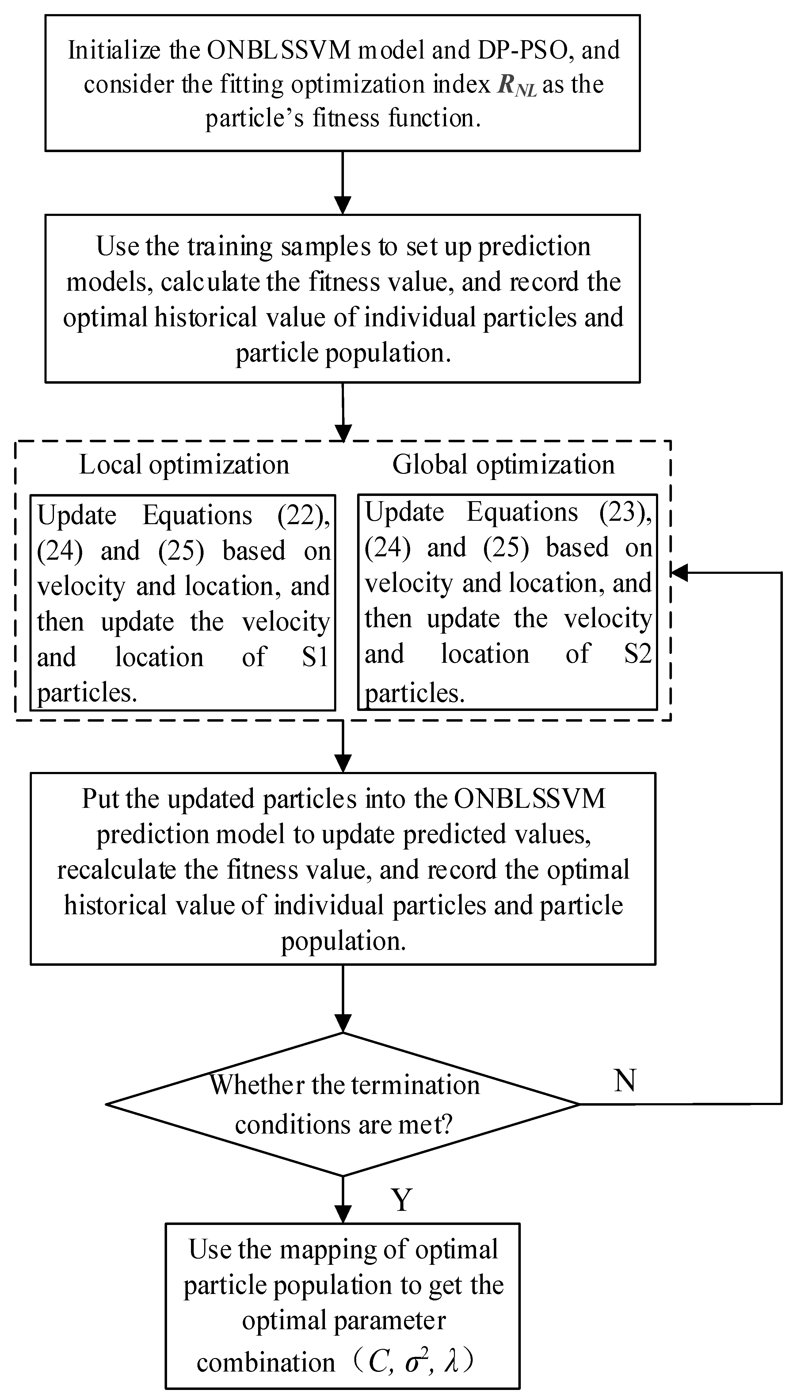
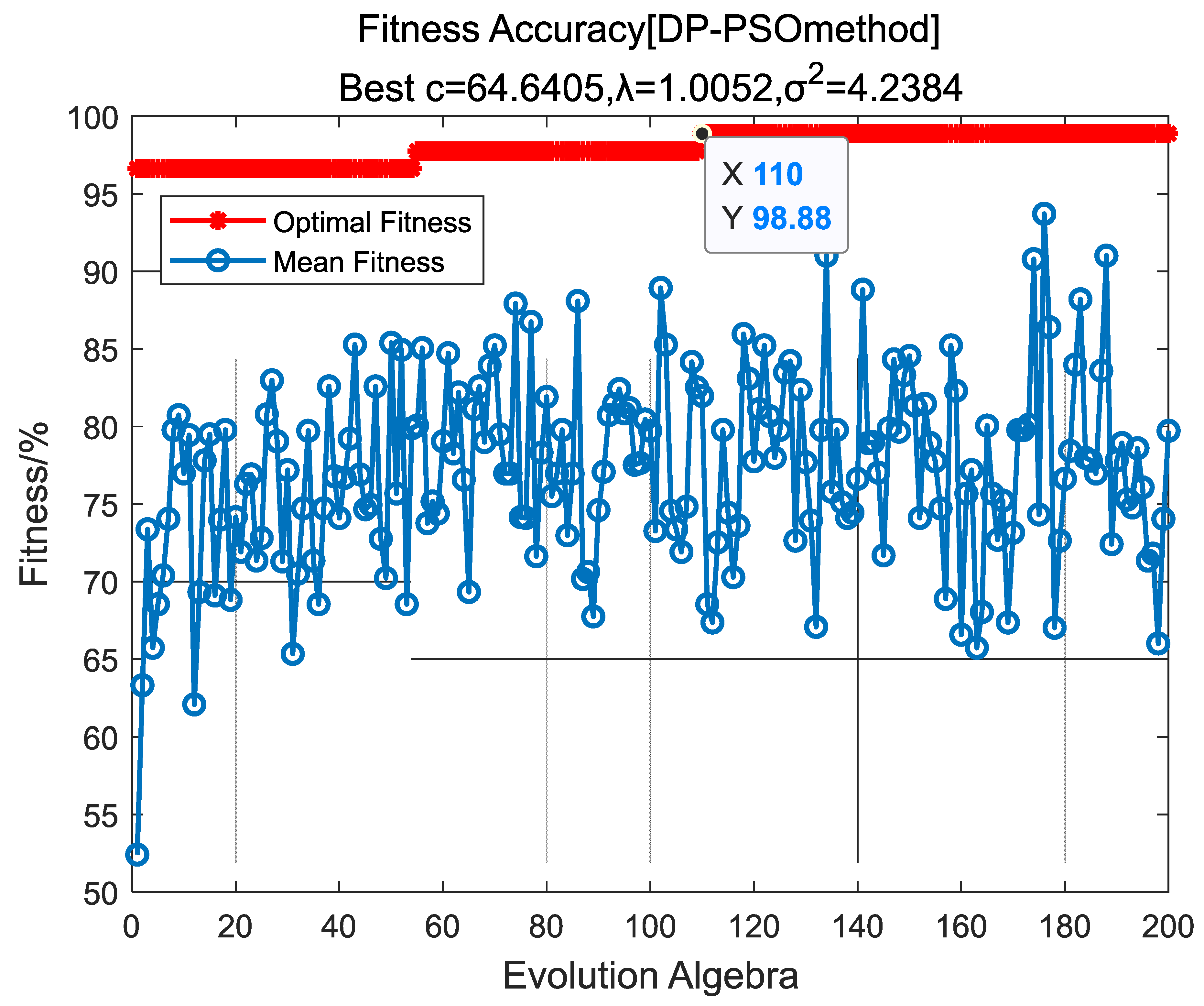
2.4. Optimized Computation of Model Parameters Based on DP-PSO

The AONBLSSVM model parameters that require optimized computation include the penalty factor C, the introduced parameter λ , and the kernel function’s breadth factor σ 2 (the Gaussian kernel function is adopted for the model). During the modeling process (based on given samples), it is a top priority to obtain combined optimal solutions of model parameters for modeling [52].
Particle-swarm optimization (PSO) works well in function optimization [53,54], but it is easily trapped at extreme points on the local scale [55] and its convergence rate at the later period is quite slow [56,57]. To make up for the defects of PSO, the concept of population co-evolution was introduced into PSO in this study [58,59,60], and online dynamic adjustment of the acceleration factor [61] was adopted for the tracking of current search results and the online real-time rectification of search strategies.
The specific method is shown as follows: the particle swarm s is partitioned into two sub-swarms Q 1 and Q 2 . Q 1 contains s 1 particles, while Q 2 consists of s 2 particles; s = s 1 + s 2 . Q 1 adopts the rapidly convergent evolution equation for fast and optimized convergence within a small range between the optimal global position and the optimal individual position; Q 2 adopts the evolution equation with global searching ability. When a new optimal global position is searched, Q 1 is guided to reach the new optimal position for local searching through information exchange between individuals.
Specific evolution equations are shown below:
Q 1 : v i j 1 ( t + 1 ) = w 1 × v i j 1 ( t ) + c 1 × r a n d ( ) × ( p 1 i j ( t ) x i j 1 ( t ) ) + c 2 × r a n d ( ) × ( p g j 1 ( t ) x i j 1 ( t ) )
where v i j 1 ( t + 1 ) is the velocity of the particle at time t + 1; p i j 1 ( t ) is the optimal historical position of the particle at time t; p g j 1 ( t ) is the historical optimal position of the population Q 1 ; x i j 1 ( t ) and v i j 1 ( t ) are the position and velocity of the particle at time t; the inertia weight w 1 = 0.3 ; c 1 and c 2 are the acceleration factors; and r a n d ( ) is a random number within the range of [ 0 , 1 ] .
Q 2 : v i j ( t + 1 ) = w ( t ) × v i j ( t ) + c 1 × r 1 j ( t ) × ( p i j ( t ) x i j ( t ) ) + c 2 × r 2 j ( t ) × ( p g j ( t ) x i j ( t ) ) w ( t ) = 0.9 t T max × 0.5
where v i j 2 ( t + 1 ) is the velocity of the particle at time t + 1; p i j 2 ( t ) is the optimal historical position of the particle at time t;  p g j 2 ( t ) is the historical optimal position of the population Q 2 ; x i j 2 ( t ) and v i j 2 ( t ) are the position and velocity of the particle at time t; the inertia weight w 2 ( t ) is the inertia weight; c 1 and c 2 are the acceleration factors; and r 1 j ( t ) and r 2 j ( t ) are random numbers within the range of [ 0 , 1 ] .
Acceleration factors c 1   and   c 2 of dynamic adjustment Equations (22) and (23) in the arc-tangent function are adopted in order to adjust the search strategy in a real-time manner. The equations for c 1   and   c 2 are written as:
c 1 ( t ) = c 1 s t a r t ( c 1 s t a r t c 1 e n d ) × ( arctan ( 20 × t / T max e ) + arctan ( e ) ) / l
c 2 ( t ) = c 2 s t a r t ( c 2 s t a r t c 2 e n d ) × ( arctan ( 20 × t / T max e ) + arctan ( e ) ) / l
where in c 1 s t a r t   and   c 2 s t a r t are the initial values of c 1   and   c 2 , respectively;  c 1 e n d   and   c 2 e n d are final values of c 1   and   c 2 ,   respectively ;   T max is the maximum evolution algebra; e is the adjustment factor; l = a r c t a n ( 20 e ) + a r c t a n e .
The process of optimizing the model parameters is shown in Figure 2, and the optimization shall terminate when the following conditions are met: (1) the fitting-optimization index [62] R N L = 1 ( y i y i ) 2 / y i 2 between the predicted and target values satisfies the preset error, where y i is real value and y i is predicted value; (2) the preset T max is achieved.

3. Simulation Experiments and Result Analyses

3.1. Establishment of Degradation Models for Key Components

The DC–DC-converter circuit designed in this study is a Boost circuit. As shown below Figure 3, the circuit achieves an input voltage of 12 Vdc, an output voltage of 24 Vdc, an output   ripple   voltage   ( V o u t ( max ) V o u t ( min ) ) 0.1 V o u t , and an output power P o u t = 200   W ( MAX ) .
By analyzing the failure mechanisms of key components such as the electrolytic capacitor, power MOSFET, diode, and electrical inductor, the performance-degradation models for various components were established to configure the changes in the parameters of components during the circuit-degradation process. On this basis, a circuit-level simulation and performance-degradation analysis were carried out, thus achieving fault prediction and service-life estimation of power-converter circuits.
Performance-degradation models of key components can be obtained from the following equations:
(1)
Performance-Degradation Model of Electrolytic Capacitor
Capacitors in real life are all found with the equivalent-series resistance (ESR), among which the ESR for electrolytic capacitors is the largest. Its degradation model is described as [63,64]:
E S R 1 = E S R ( 0 ) 1 · ( 1 k E S R · t E S R · e 4700 ( 273 + T E S R ) )
This model reveals the mathematical relationship between E S R ( t ) and its initial value E S R ( 0 ) , where T E S R represents the kernel temperature, t E S R refers to the working time, and k E S R is a parameter that is only related to the capacitive material.
The wastage of electrolytes increases over time. The performance-degradation model [65], i.e., Δ C v a l u e ( t c ) = C v a l u e ( 0 ) C v a l u e ( t c ) C v a l u e ( 0 ) % of Cvalue (capacity of capacitor), is expressed as:
Δ C v a l u e ( t C ) = 0.01 ( e α 1 t C β 1 )
where t c refers to the working time and α 1 and β 1 are degradation parameters of the model.
The failure condition of the electrolytic capacitor is set as follows [66]: E S R ( t E S R ) 3 × E S R ( 0 ) ; Δ C v a l u e   ( t c ) 20 % × C ( 0 ) .
By referring to the component manual, it can be known that E S R ( 0 ) = 0.02   Ω in the working environment of T E S R = 27   . Supposing that E S R ( t E S R ) = 3 × E S R ( 0 ) ,   t E S R = 1500   h , and E S R ( 1500 ) = 0.06   Ω , it can be inferred from Equation (26) that k E S R = 2839 . Therefore, the degradation model of ESR over time is established as follows:
E S R ( t E S R ) = E S R ( 0 ) 1 k E S R t E S R exp ( 4700 T E S R + 273 ) = 0.02 1 0.000444 t E S R
where in C v a l u e ( 0 ) = 1000 u F . Supposing that Δ C v a l u e ( t c ) = 20 % , t c = 1500   h , and the parameter β 1   = 1, it can be known from Equation (27) that α 1 = 0.002030 . Then, the degradation model of Cvalue over time is expressed as:
C v a l u e ( t C ) = C v a l u e ( 0 ) [ 1 Δ C v a l u e ( t C ) ] = 1000 × 10 6 [ 1 0.01 × ( e 0.002030 t c 1 ) ]
(2)
Performance-Degradation Model of Power MOSFET
On-resistance R o n is a key parameter that determines the dissipated power of the MOSFET, whose empirical degradation model is written as:
Δ R o n ( t M O S ) = α 2 ( e b 2 t M O S 1 )
where in t M O S refers to the MOSFET’s working time; a 2 and b 2 are degradation parameters of the model. When R o n > 0.045   Ω , it is believed that the MOSFET is out of work [67].
By referring to the component manual, it can be known that 75N05 has a R o n ( 0 ) = 0.02   Ω , so it is deemed that the MOSFET is out of work when R o n increases to 0.065   Ω . Supposing that R o n = 0.045   Ω ,   t M O S = 1500   h , and the model parameter a 2 = 0.003 it can be deduced from Equation (30) that the parameter b 2 = 0.00185 . Therefore, R o n is expressed as:
R o n ( t M O S ) = R o n ( 0 ) + Δ R o n = 0.02 + 0.003 ( e 0.00185 t M O S 1 )
(3)
Performance-Degradation Model of Inductor
During the working process of the inductor, the inductance gradually decreases along with the increase in temperature, making it impossible for the circuit to function normally. The performance-degradation model [68] of the inductor used in this circuit is described as:
L ( t L ) = L ( 0 ) α 3 t L
where t L , α 3 and L ( 0 ) represent the duration, the performance-degradation parameter, and the initial nominal value, respectively.
Previous experience suggests that the inductor is out of work when L ( t L ) < 0.8 × L ( 0 ) [69]. Supposing that L ( t L ) = 0.8 L ( 0 ) , t L = 1500   h , it can be deduced from Equation (32) that α 3 = 0.0044 . Therefore, L value at time t L is expressed as:
L ( t L ) = L ( 0 ) 0.0044 t L
(4)
Performance-Degradation Model of Power Diode
By referring to the MOSFET, the on-resistance R D can be employed as a characteristic parameter to judge whether a power diode functions normally. Besides, it is believed that the power diode is out of work when R D is greater than the initial value 0.045   Ω [70,71]. The degradation model [72,73] of Δ R D can be described as:
Δ R D ( t D ) = α 4 ( e b 4 t D 1 )
where t D is the working time of the power diode; α 4 and b 4 are degradation parameters of the model.
Supposing that R D has an initial value of R D ( 0 ) = 0.01   Ω with reference to the component manual, it is believed that the power diode is out of work when R D increases to 0.055   Ω . Supposing that it takes 1500 h for the on-resistance to increase to 0.055   Ω , and that α 4 = 0.00025 , it can be known from Equation (34) that b 4 = 0.0035 . Therefore, the on-resistance R D at time t D is expressed as:
R D ( t D ) = R D ( 0 ) + Δ R D ( t D ) = 0.01 + 0.00025 ( e 0.0035 t D 1 )

3.2. Selection of Characteristic Parameters for Circuit-Level Faults

The simulation circuit of the DC–DC converter was built in the simulation software saber, with an input voltage of 12 Vdc and an output voltage of 24 Vdc. The simulation time was set as 30 ms, with a simulation-step size of 1 us. When the circuit output reached a stable state, the output voltage V o u t was sampled, and the simulation waveform was drawn.
It can be known by observing the V o u t waveform in Figure 4 that the waveform of the output voltage tends to be stable when the simulation experiment is conducted for 5 ms; the output voltage V o u t fluctuates around 24 V because the DC–DC converter switches between charging and discharging modes during the working process. Consequently, its output-voltage waveform does not exhibit stable DC voltage but is found to be fluctuating, suggesting the presence of ripple voltage U P P .
Based on the performance-degradation models of various components from Equation (26) to Equation (35), different values were set for the parameters of each component at a time interval of Δ t ( Δ t = 100   h ) in sequence since t = 0 , which were then inputted into the DC–DC simulation circuits of saber for the simulation experiments. It can be known from the simulation analysis that as the working time increases, the waveform of the output ripple voltage U P P always tends to expand over time when the performance of multiple key components C 2 C 5 , L 1 , M B R 20100 and 75 N 75 degrade at the same time, and the changes are quite noticeable, as detailed in Table 1. Therefore, the output ripple voltage U P P was chosen in this study as a characteristic parameter for the faults of the DC–DC-converter circuits. According to the performance indicators, if U P P > 0.24   V , then the circuit is trapped in a fault. The ripple voltage can be obtained by using the equation U P P = V o u t ( max ) V o u t ( min ) .
Different values were set for the parameters of each component every 1 h in sequence since t = 0 , which were then inputted into the DC–DC simulation circuits of the saber to retain the output voltage V o u t within the stable band (10–30 ms). A total of 1400 groups of ripple voltages U P P from 1 1400   h were obtained using the equation U P P = V o u t ( max ) V o u t ( min ) , which formed the characteristic-parameter sample sets of the soft fault of the circuit.

3.3. Determination of Parameters for the Prediction Model

DP-PSO was adopted for the optimized computation of the prediction-model parameters, including the penalty factor C , the introduced parameter λ , and the kernel breadth factor σ 2 . Three hundred samples were selected, which were set with the following parameters: the swarm quantity S = 100 , the sub-swarm quantity s 1 = 35 and s 2 = 65 , the maximum evolution algebra T m a x = 200 the acceleration factor c 1 s t a r t   = 2.75 ,   c 1 e n d   = 1.25 ,   c 2 s t a r t = 0.5   and   c 2 e n d = 2.25 . The penalty factor C varied within [ 10 2 ,   10 3 ] the Gaussian kernel function breadth factor σ 2 varied within [ 10 2 ,   10 2 ] and the parameter λ varied within [ 10 3 ,   10 ] .
The optimization results are as shown in Figure 5. The algorithm converged after 110 iterations, and the optimal parameter combination was obtained:
C = 64.605 ,   λ = 1.0052 ,   σ 2 = 4.2384 .

3.4. Testing of Prediction-Model Performance

(1)
Testing of the Prediction Efficiency of the Model
Output ripple voltages within 1 300   h were chosen as the training samples, and those within 301 625   h were used as the testing samples. The performance periods of 325 time-series predictions in nine groups were compared and analyzed under different lengths of sliding-time windows for the OLS-SVM and ONBLSSVM, whose results are shown in Figure 6. As Figure 6 shows, the ONBLSSVM has higher prediction efficiency than the OLS-SVM. With the increase in the sliding-window length, the prediction time of the ONBLSSVM increases more slowly than OLS-SVM, and this superiority becomes more significant as the sliding-time window becomes longer.
(2)
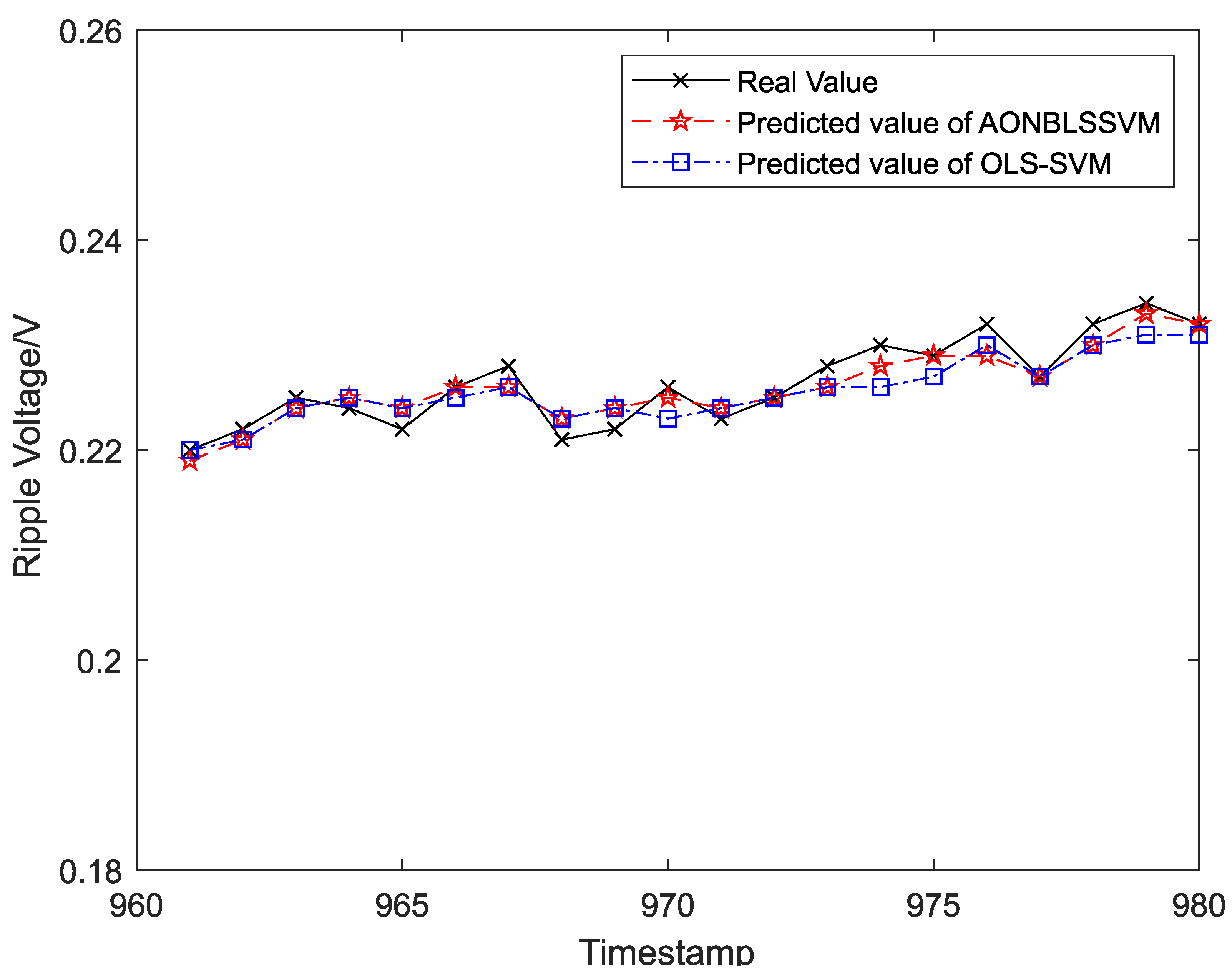
Testing of Prediction Accuracy of the Model
To balance the prediction accuracy and the modeling speed, it is necessary to choose a sliding-time window with appropriate length. The length can be calculated via the adaptive-adjustment algorithm (proposed in Section 2.3), and the simulation-experiment results are shown in Figure 7. With the prediction error θ 0.01   V and the threshold ε   = 0.05, the window length was finalized to be 90.
Output ripple voltages within 1 300   h were chosen as the training samples to form the sliding-time window and obtain the initial prediction model. To display the prediction effects more clearly and intuitively, output ripple voltages within 301 1400   h were classified into 55 groups in the time sequence, and each group was assigned 20 ripple-voltage values. Five data groups (100 ripple-voltage values in total) were chosen as test samples in time sequence for the evaluation of fitting between the real and predicted values. The curve-fitting results are shown in Figure 8, Figure 9, Figure 10, Figure 11 and Figure 12, the computational formulas for the chosen fitting-assessment indicator are as follows, where n is the number of test samples, y i is the real value, y i is predicted value, and the specific computational values are provided in Table 2 and Table 3:
Mean   Average   Deviation   ( MAD ) = 1 n i = 1 n | y i y i |
Mean   Average   Percentage   Error   ( MAPE ) = 1 00 % n i = 1 n | y i y y i |
Theil s   Inequality   Coefficient ( Theil   IC ) = 1 n i = 1 n ( y i y i ) 2 1 n i = 1 n y i 2 + 1 n i = 1 n y i 2

3.5. Analysis of Simulation Results

It can be seen from Figure 6 that the ONBLSSVM outperforms the OLS-SVM in terms of prediction efficiency, and the superiority becomes more significant when the sliding-time window is longer. Figure 11 shows that in combination with the output-ripple-voltage threshold (0.24 V), the DC–DC converter reaches its service life when the predicted value reaches the preset failure threshold (1048 h) for the first time. The fitting results of the predicted- and target-value curves in Figure 8, Figure 9, Figure 10, Figure 11 and Figure 12 vividly present that although the predicted values from the OLS-SVM are closer to real characteristic values than those from algorithm proposed herein at certain moments (379, 641, 975, 1057, etc.), our predicted-value curves generally fit better with the actual characteristic-value curves, suggesting that our algorithm has a higher prediction accuracy than the OLS-SVM.
The indicator data in Table 2 and Table 3 show that by comparing the three prediction and assessment indicators MAD, MAPE, and Theil IC in the five simulation experiments, our algorithm behaves better than the OLS-SVM, reconfirming its superior prediction accuracy.

4. Conclusions

In the AONBLSSVM algorithm, the bias term in the regression function was eliminated by optimizing the structural-risk forms of the LSSVM, and an online-learning method based on square-root decomposition was thus designed, which simplified the computation of the Lagrange multiplier and bias b during the dynamic updates of the model, avoided cumbersome computation, and reduced the modeling time. The adaptive selection of the sliding-time-window length was also realized to ensure the model could eliminate the constraints of old samples after adding new ones and achieve rapid updates. By adopting this method, monitoring data can be gradually injected into training sets over time, and historical training results can be exploited to the fullest in order to update the model online, thus effectuating the online monitoring of the DC–DC-converter circuit (a nonlinear time-varying system).
The AONBLSSVM algorithm relies much on the model parameters in terms of prediction accuracy. When the parameters are not well-configured, the prediction accuracy will be low. In DP-PSO, the concept of population co-evolution is introduced to the PSO to adjust the search strategies in a real-time manner so that the improved algorithm has stronger convergence and higher accuracy, thereby providing better prediction effects for the optimization of model parameters. DP-PSO is introduced for the optimized computation of model parameters, ensuring that a prediction model with higher accuracy will be established in a shorter time.
According to the simulation results, the circuit-fault-prediction model proposed herein showed good prediction and tracking capabilities for the soft fault of the DC–DC-converter circuit in a precise plot-seeder electric-drive system, and can be used for predicting the faults at the next moment in a fast and accurate manner. Furthermore, in combination with the circuit-failure threshold, it can provide a theoretical basis and support for predicting the service life of the DC–DC-converter circuit.

Author Contributions

Conceptualization, Y.H.; methodology, Y.H.; software, Z.W. and Z.D.; validation, X.C.; formal analysis, Y.H and X.C.; investigation, Y.H and X.C.; data curation, Z.W and Z.D.; writing—original draft preparation, Y.H and Z.W.; writing—review and editing, X.C.; visualization, Z.W. and Z.D.; funding acquisition, X.C. All authors have read and agreed to the published version of the manuscript.

Funding

This work is funded by the National Key Research and Development Program of China (2019YFE0125400), the program of Research Funds for the Province-owned Research Institutes in Heilongjiang Province (CZKYF2020B007), and the Scientific Research Project of Heilongjiang Academy of Agricultural Sciences (HNK2019CX20-02).

Institutional Review Board Statement

Not applicable.

Informed Consent Statement

Not applicable.

Data Availability Statement

Not applicable.

Conflicts of Interest

The authors declare no conflict of interest.

Nomenclature

DC–DCDirect Current to Direct Current
AONBLSSVMAdaptive Online Non-bias Least-Square Support-Vector Machine
DP-PSODouble-Population Particle-Swarm Optimization
OLS-SVMOnline Least-Square Support-Vector Machine
MOSFETMetal-Oxide-Semiconductor Field-Effect Transistor
IGBT Insulated Gate Bipolar Translator
RcEquivalent-Series Resistance
P c ¯ Average Power Loss of Capacitor
ICEffective Value of Capacitive Current
CvalueCapacity of Capacitor
SISOSingle Input–Single Output
MISOMultiple Input–Single Output
CCMContinuous Conduction Mode
DCMDiscontinuous Conduction Mode
RonDrain-source On-resistance of Metal-Oxide-Semiconductor Field-Effect Transistor
SVMSupport-Vector Machine
LSSVMLeast-Square Support-Vector Machine
ONBLSSVMOnline Non-bias Least-Square Support-Vector Machine
KKT conditionsKarush–Kuhn–Tucker conditions
CPenalty Factor
λ Introduced Parameter
σ 2 Gaussian Kernel Function Breadth Factor
θ Prediction-Error Threshold
ε Refers to The Relative Decrement Threshold
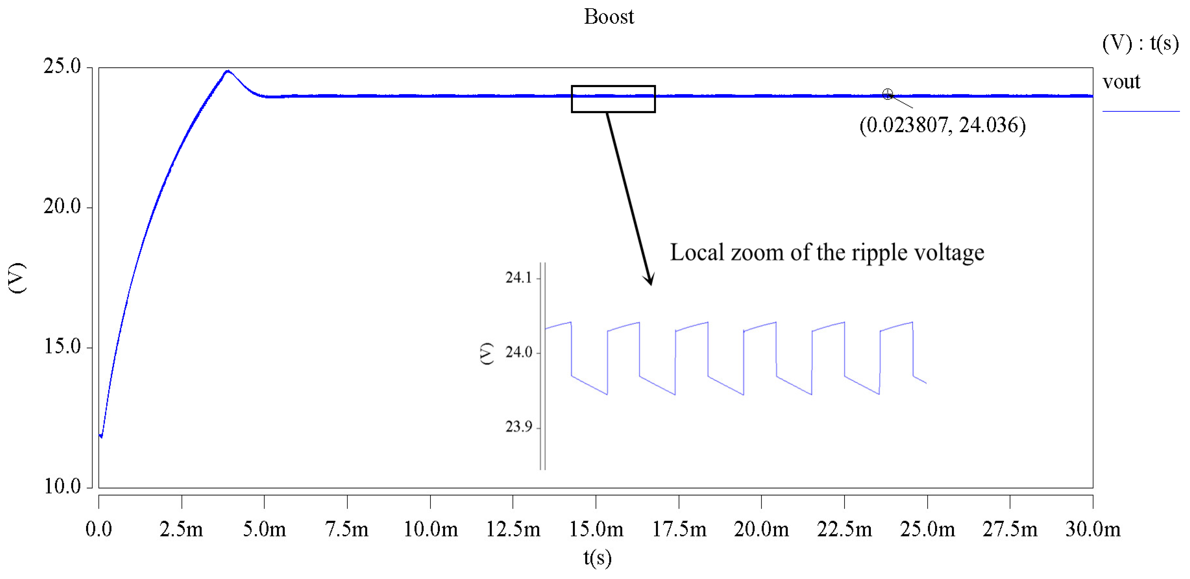
VoutOutput Voltage of Direct Current to Direct Current
PoutOutput Power of Direct Current to Direct Current
UppRipple Voltage
tTime
tTime Interval
MADMean Average Deviation
MAPEMean Average Percentage Error
Theil ICTheil’s Inequality Coefficient

References

  1. Gautam, P.V.; Kushwaha, H.; Kumar, A.; Kumar, D. Mechatronics Application in Precision Sowing: A Review. Int. J. Curr. Microbiol. Appl. Sci. 2019, 8, 1793–1807. [Google Scholar] [CrossRef]
  2. Lian, Z.; Wang, J.; Yang, Z.; Shang, S. Development of plot-sowing mechanization in China. Trans. Chin. Soc. Agric. Eng. 2012, 28, 140–145. [Google Scholar]
  3. Vichare, N.M.; Pecht, M.G. Prognostics and health management of electronics. IEEE Trans. Compon. Packag. Technol. 2006, 29, 222–229. [Google Scholar] [CrossRef]
  4. Saha, S.; Celaya, J.R.; Vashchenko, V.; Mahiuddin, S.; Goebel, K.F. Accelerated aging with electrical overstress and prognostics for power MOSFETs. In Proceedings of the IEEE 2011 EnergyTech, Cleveland, OH, USA, 25–26 May 2011; pp. 1–6. [Google Scholar]
  5. Patil, N.; Celaya, J.; Das, D.; Goebel, K.; Pecht, M. Precursor Parameter Identification for Insulated Gate Bipolar Transistor (IGBT) Prognostics. IEEE Trans. Reliab. 2009, 58, 271–276. [Google Scholar] [CrossRef]
  6. Zhou, Y.; Ye, X.; Zhai, G. Degradation model and maintenance strategy of the electrolytic capacitors for electronics applications. In Proceedings of the 2011 Prognostics and System Health Management Conference, Shenzhen, China, 24–25 May 2011; pp. 1–6. [Google Scholar]
  7. Ren, L.; Gong, C.; Zhao, Y. An Online ESR Estimation Method for Output Capacitor of Boost Converter. IEEE Trans. Power Electron. 2019, 34, 10153–10165. [Google Scholar] [CrossRef]
  8. Dusmez, S.; Heydarzadeh, M.; Nourani, M.; Akin, B. Remaining Useful Lifetime Estimation for Power MOSFETs Under Thermal Stress With RANSAC Outlier Removal. IEEE Trans. Ind. Inform. 2017, 13, 1271–1279. [Google Scholar] [CrossRef]
  9. Li, Z.; Zheng, Z.; Outbib, R. A prognostic methodology for power MOSFETs under thermal stress using echo state network and particle filter. Microelectron. Reliab. 2018, 88–90, 350–354. [Google Scholar] [CrossRef] [Green Version]
  10. Duan, X.; Zou, J.; Li, B.; Wu, Z.; Lei, D. An Online Monitoring Scheme of Output Capacitor’s Equivalent Series Resistance for Buck Converters Without Current Sensors. IEEE Trans. Ind. Electron. 2020, 68, 10107–10117. [Google Scholar] [CrossRef]
  11. Tang, S.; Dong, S.; Liu, Y.; Zhang, Q. Current-sensorless online ESR monitoring of capacitors in boost converter. J. Eng. 2019, 2019, 2569–2574. [Google Scholar] [CrossRef]
  12. Lu, W.G.; Lu, X.; Han, J.; Zhao, Z.; Du, X. Online Estimation of ESR for DC-Link Capacitor of Boost PFC Converter Using Wavelet Transform Based Time–Frequency Analysis Method. IEEE Trans. Power Electron. 2019, 35, 7755–7764. [Google Scholar] [CrossRef]
  13. Rodríguez-Blanco, M.A.; Cervera-Cevallos, M.; Vázquez-Ávila, J.L.; Islas-Chuc, M.S. Fault detection methodology for the IGBT based on measurement of collector transient current. In Proceedings of the 2018 14th International Conference on Power Electronics (CIEP), Cholula, Puebla, Mexico, 24–26 October 2018. [Google Scholar]
  14. Li, X.; Xu, D.; Zhu, H.; Cheng, X.; Yu, Y.; Ng, W.T. Indirect IGBT Over-Current Detection Technique Via Gate Voltage Monitoring and Analysis. IEEE Trans. Power Electron. 2018, 34, 3615–3622. [Google Scholar] [CrossRef]
  15. XSun, X.; Huang, M.; Liu, Y.; Zha, X. Investigation of artificial neural network algorithm based IGBT online condition monitoring. Microelectron. Reliab. 2018, 88–90, 103–106. [Google Scholar]
  16. Dusmez, S.; Bhardwaj, M.; Sun, L.; Akin, B. A software frequency response analysis method to monitor degradation of power MOSFETs in basic single-switch converters. In Proceedings of the 2016 IEEE Applied Power Electronics Conference and Exposition (APEC), Long Beach, CA, USA, 20–24 March 2016; pp. 505–510. [Google Scholar]
  17. Dusmez, S.; Bhardwaj, M.; Sun, L.; Akin, B. In Situ Condition Monitoring of High-Voltage Discrete Power MOSFET in Boost Converter Through Software Frequency Response Analysis. IEEE Trans. Ind. Electron. 2016, 63, 7693–7702. [Google Scholar] [CrossRef]
  18. Wu, Y.; Wang, Y.; Jiang, Y.; Sun, Q. Multiple parametric faults diagnosis for power electronic circuits based on hybrid bond graph and genetic algorithm. Measurement 2016, 92, 365–381. [Google Scholar] [CrossRef]
  19. Sun, Q.; Wang, Y.; Jiang, Y.; Wu, Y. Online component-level soft fault diagnostics for power converters. In Proceedings of the 2016 Prognostics and System Health Management Conference (PHM-Chengdu), Chengdu, China, 19–21 October 2016; pp. 1–5. [Google Scholar]
  20. Sun, Q.; Wang, Y.; Jiang, Y.; Shao, L. Condition Monitoring and Prognosis of Power Converters Based on CSA-LSSVM. In Proceedings of the 2017 International Conference on Sensing, Diagnostics, Prognostics, and Control (SDPC), Shanghai, China, 16–18 August 2017; pp. 524–529. [Google Scholar]
  21. Chen, C.; Ye, X.; Wang, H.; Zhai, G.; Wan, R. In-situ prognostic method of power MOSFET based on miller effect. In Proceedings of the 2017 Prognostics and System Health Management Conference (PHM-Harbin), Harbin, China, 9–12 July 2017; pp. 1–5. [Google Scholar]
  22. Sastry, A.; Kulasekaran, S.; Flicker, J.; Ayyanar, R.; TamizhMani, G.; Roy, J.; Srinivasan, D.; Tilford, I. Failure modes and effect analysis of module-level power electronics. In Proceedings of the 2015 IEEE 42nd Photovoltaic Specialist Conference (PVSC), New Orleans, LA, USA, 14–19 June 2015; pp. 1–3. [Google Scholar]
  23. Long, B.; Xian, W.; Li, M.; Wang, H. Improved diagnostics for the incipient faults in analog circuits using LSSVM based on PSO algorithm with Mahalanobis distance. Neurocomputing 2014, 133, 237–248. [Google Scholar] [CrossRef]
  24. Kordestani, M.; Samadi, M.F.; Saif, M.; Khorasani, K. A New Fault Prognosis of MFS System Using Integrated Extended Kalman Filter and Bayesian Method. IEEE Trans. Ind. Inform. 2018. [Google Scholar] [CrossRef]
  25. Wan, M.; Wang, Z.; Si, L.; Tan, C.; Wang, H. An Initial Alignment Technology of Shearer Inertial Navigation Positioning Based on a Fruit Fly-Optimized Kalman Filter Algorithm. Comput. Intell. Neurosci. 2020, 2020, 8876918. [Google Scholar] [CrossRef]
  26. Boškoski, P.; Gašperin, M.; Petelin, D.; Juričić, Đ. Bearing fault prognostics using Rényi entropy-based features and Gaussian process models. Mech. Syst. Signal Processing 2015, 52, 327–337. [Google Scholar] [CrossRef]
  27. Chen, N.; Yu, R.; Chen, Y.; Xie, H. Hierarchical method for wind turbine prognosis using SCADA data. IET Renew. Power Gener. 2017, 11, 403–410. [Google Scholar] [CrossRef]
  28. Elforjani, M.; Shanbr, S. Prognosis of Bearing Acoustic Emission Signals Using Supervised Machine Learning. IEEE Trans. Ind. Electron. 2018, 65, 5864–5871. [Google Scholar] [CrossRef] [Green Version]
  29. Javed, K.; Gouriveau, R.; Zerhouni, N. A New Multivariate Approach for Prognostics Based on Extreme Learning Machine and Fuzzy Clustering. IEEE Trans. Cybern. 2015, 45, 2626–2639. [Google Scholar] [CrossRef] [PubMed] [Green Version]
  30. Shang, S.; He, K.-N.; Wang, Z.-B.; Yang, T.; Liu, M.; Li, X. Sea Clutter Suppression Method of HFSWR Based on RBF Neural Network Model Optimized by Improved GWO Algorithm. Comput. Intell. Neurosci. 2020, 2020, 8842390. [Google Scholar] [CrossRef] [PubMed]
  31. Li, G.; Ma, X.; Yang, H. A Hybrid Model for Forecasting Sunspots Time Series Based on Variational Mode Decomposition and Backpropagation Neural Network Improved by Firefly Algorithm. Comput. Intell. Neurosci. 2018, 2018, 3713410. [Google Scholar] [CrossRef] [PubMed]
  32. Gao, Q.; Ma, P. Graph Neural Network and Context-Aware Based User Behavior Prediction and Recommendation System Research. Comput. Intell. Neurosci. 2020, 2020, 8812370. [Google Scholar] [CrossRef]
  33. Daroogheh, N.; Baniamerian, A.; Meskin, N.; Khorasani, K. Prognosis and Health Monitoring of Nonlinear Systems Using a Hybrid Scheme Through Integration of PFs and Neural Networks. IEEE Trans. Syst. Man, Cybern. Syst. 2016, 47, 1990–2004. [Google Scholar] [CrossRef]
  34. Haque, M.S.; Choi, S.; Baek, J. Auxiliary Particle Filtering-Based Estimation of Remaining Useful Life of IGBT. IEEE Trans. Ind. Electron. 2017, 65, 2693–2703. [Google Scholar] [CrossRef]
  35. Tang, H.; Li, D.; Chen, W.; Xue, S. Uncertainty quantification using evidence theory in concrete fatigue damage prognosis. In Proceedings of the 2016 IEEE International Conference on Prognostics and Health Management (ICPHM), Ottawa, ON, Canada, 20–22 June 2016; pp. 1–7. [Google Scholar]
  36. Yang, Y.; Xue, D. Modified grey model predictor design using optimal fractional-order accumulation calculus. IEEE/CAA J. Autom. Sin. 2017, 4, 724–733. [Google Scholar] [CrossRef]
  37. Chen, L.; Tian, B.; Lin, W.; Ji, B.; Li, J.; Pan, H. Analysis and prediction of the discharge characteristics of the lithium–ion battery based on the Grey system theory. IET Power Electron. 2015, 8, 2361–2369. [Google Scholar] [CrossRef] [Green Version]
  38. Liu, T.; Zhu, K.; Zeng, L. Diagnosis and Prognosis of Degradation Process via Hidden Semi-Markov Model. IEEE/ASME Trans. Mechatron. 2018, 23, 1456–1466. [Google Scholar] [CrossRef]
  39. TKlingelschmidt, T.; Weber, P.; Simon, C.; Theilliol, D.; Peysson, F. Fault diagnosis and prognosis by using Input-Output Hidden Markov Models applied to a diesel generator. In Proceedings of the 2017 25th Mediterranean Conference on Control and Automation (MED), Valletta, Malta, 3–6 July 2017; pp. 1326–1331. [Google Scholar]
  40. Liu, Y.; Shuai, Q.; Zhou, S.; Tang, J. Prognosis of Structural Damage Growth Via Integration of Physical Model Prediction and Bayesian Estimation. IEEE Trans. Reliab. 2017, 66, 700–711. [Google Scholar] [CrossRef]
  41. Hu, X.; Jiang, J.; Cao, D.; Egardt, B. Battery Health Prognosis for Electric Vehicles Using Sample Entropy and Sparse Bayesian Predictive Modeling. IEEE Trans. Ind. Electron. 2015, 63, 2645–2656. [Google Scholar] [CrossRef]
  42. Suykens, J.A.K.; Vandewalle, J. Least Squares Support Vector Machine Classifiers. Neural Process. Lett. 1999, 9, 293–300. [Google Scholar] [CrossRef]
  43. Suykens, J.A.; Lukas, L.; Vandewalle, J. Sparse approximation using least squares support vector machines. In Proceedings of the 2000 IEEE International Symposium on Circuits and Systems (ISCAS), Geneva, Switzerland, 28–31 May 2000; Volume 2. [Google Scholar]
  44. Suykens, J.; Vandewalle, J.; De Moor, B. Optimal control by least squares support vector machines. Neural Netw. 2001, 14, 23–35. [Google Scholar] [CrossRef]
  45. Li, J.; Ye, M.; Meng, W.; Xu, X.; Jiao, S. A Novel State of Charge Approach of Lithium Ion Battery Using Least Squares Support Vector Machine. IEEE Access 2020, 8, 195398–195410. [Google Scholar] [CrossRef]
  46. Cheng, R.; Song, Y.; Chen, D.; Chen, L. Intelligent Localization of a High-Speed Train Using LSSVM and the Online Sparse Optimization Approach. IEEE Trans. Intell. Transp. Syst. 2017, 18, 2071–2084. [Google Scholar] [CrossRef]
  47. Kong, W.; Ding, J. Online Learning Algorithm for LSSVM Based Modeling with Time-varying Kernels. IFAC-Pap. 2018, 51, 626–630. [Google Scholar] [CrossRef]
  48. Liu, X.; Wang, Q.; Huang, R.; Wang, S.; Liu, X. A prediction method for deck-motion based on online least square support vector machine and genetic algorithm. J. Mar. Sci. Technol. 2018, 24, 382–397. [Google Scholar] [CrossRef]
  49. Ardakani, M.H.; Escudero, G.; Graells, M.; Espuña, A. Sliding Dynamic Data Window: Improving Properties of the Incremental Learning Methods. Comput. Aided Chem. Eng. 2017, 40, 1663–1668. [Google Scholar]
  50. Shao, S.; Xu, G.; Li, M.; Huang, G.Q. Synchronizing e-commerce city logistics with sliding time windows. Transp. Res. Part E Logist. Transp. Rev. 2019, 123, 17–28. [Google Scholar] [CrossRef]
  51. Youn, J.; Shim, J.; Lee, S.-G. Efficient Data Stream Clustering With Sliding Windows Based on Locality-Sensitive Hashing. IEEE Access 2018, 6, 63757–63776. [Google Scholar] [CrossRef]
  52. Song, X.; Zhao, J.; Song, J.; Dong, F.; Xu, L.; Zhao, J. Local Demagnetization Fault Recognition of Permanent Magnet Synchronous Linear Motor Based on S-Transform and PSO–LSSVM. IEEE Trans. Power Electron. 2020, 35, 7816–7825. [Google Scholar] [CrossRef]
  53. Liu, H.-H.; Chang, L.-C.; Li, C.-W.; Yang, C.-H. Particle Swarm Optimization-Based Support Vector Regression for Tourist Arrivals Forecasting. Comput. Intell. Neurosci. 2018, 2018, 6076475. [Google Scholar] [CrossRef] [PubMed]
  54. Cho, M.-Y.; Hoang, T.T. Feature Selection and Parameters Optimization of SVM Using Particle Swarm Optimization for Fault Classification in Power Distribution Systems. Comput. Intell. Neurosci. 2017, 2017, 4135465. [Google Scholar] [CrossRef] [PubMed]
  55. Qi, Y.; Ding, F.; Xu, F.; Yang, J. Channel and Feature Selection for a Motor Imagery-Based BCI System Using Multilevel Particle Swarm Optimization. Comput. Intell. Neurosci. 2020, 2020, 8890477. [Google Scholar] [CrossRef]
  56. Wang, Z.; Wang, X.-H.; Wang, L.-Z.; Hu, X.-F.; Fan, W.-H. Research on electric vehicle (EV) driving range prediction method based on PSO-LSSVM. In Proceedings of the 2017 IEEE International Conference on Prognostics and Health Management (ICPHM), Dallas, TX, USA, 19–21 June 2017; pp. 260–265. [Google Scholar]
  57. Li, B.; Tian, X. An Effective PSO-LSSVM-Based Approach for Surface Roughness Prediction in High-Speed Precision Milling. IEEE Access 2021, 9, 80006–80014. [Google Scholar] [CrossRef]
  58. Sarayloo, M.; Gambi, E.; Spinsante, S. A New Approach to Sequence Construction With Good Correlation by Particle Swarm Optimization. J. Commun. Softw. Syst. 2015, 11, 127–135. [Google Scholar] [CrossRef]
  59. Elmasry, W.; Akbulut, A.; Zaim, A.H. Evolving deep learning architectures for network intrusion detection using a double PSO metaheuristic. Comput. Netw. 2019, 168, 107042. [Google Scholar] [CrossRef]
  60. Bangyal, W.H.; Hameed, A.; Alosaimi, W.; Alyami, H. A New Initialization Approach in Particle Swarm Optimization for Global Optimization Problems. Comput. Intell. Neurosci. 2021, 2021, 6628889. [Google Scholar] [CrossRef]
  61. Bilal; Rani, D.; Pant, M.; Jain, S.K. Dynamic programming integrated particle swarm optimization algorithm for reservoir operation. Int. J. Syst. Assur. Eng. Manag. 2020, 11, 515–529. [Google Scholar] [CrossRef]
  62. Tian, Y.; Tang, A.; Yu, Y. Transmission model and statistical analysis for indoor wireless sensor network channels. J. Control Decis. 2014, 29, 1135–1138. (In Chinese) [Google Scholar]
  63. Lahyani, A.; Venet, P.; Grellet, G.; Viverge, P.-J. Failure prediction of electrolytic capacitors during operation of a switchmode power supply. IEEE Trans. Power Electron. 1998, 13, 1199–1207. [Google Scholar] [CrossRef]
  64. Celaya, J.R.; Kulkarni, C.S.; Biswas, G.; Goebel, K. Towards a model-based prognostics methodology for electrolytic capacitors: A case study based on electrical overstress accelerated aging. Int. J. Progn. Health Manag. 2012, 3, 33. [Google Scholar] [CrossRef]
  65. Celaya, J.R.; Kulkarni, C.S.; Biswas, G.; Saha, S.; Goebel, K. A model-based prognostics methodology for electrolytic capacitors based on electrical overstress accelerated aging. In Proceedings of the Annual Conference of the PHM Society, Montreal, QC, Canada, 25–29 September 2011; Volume 3, p. 1. [Google Scholar]
  66. Kulkarni, C.S.; Celaya, J.R.; Biswas, G.; Goebel, K. Accelerated aging experiments for capacitor health monitoring and prognostics. In Proceedings of the 2012 IEEE AUTOTESTCON Proceedings, Anaheim, CA, USA, 10–13 September 2012; pp. 356–361. [Google Scholar]
  67. Celaya, J.R.; Saxena, A.; Kulkarni, C.S.; Saha, S.; Goebel, K. Prognostics approach for power MOSFET under thermal-stress aging. In Proceedings of the 2012 Proceedings Annual Reliability and Maintainability Symposium, Reno, NV, USA, 23–26 January 2012; pp. 1–6. [Google Scholar]
  68. Fukuda, Y.; Inoue, T.; Mizoguchi, T.; Yatabe, S.; Tachi, Y. Planar inductor with ferrite layers for DC-DC converter. IEEE Trans. Magn. 2003, 39, 2057–2061. [Google Scholar] [CrossRef]
  69. Givi, H.; Farjah, E.; Ghanbari, T. A Comprehensive Monitoring System for Online Fault Diagnosis and Aging Detection of Non-Isolated DC–DC Converters’ Components. IEEE Trans. Power Electron. 2018, 34, 6858–6875. [Google Scholar] [CrossRef]
  70. Jiang, X.; Zhai, D.; Chen, J.; Yuan, F.; Li, Z.; He, Z.; Shen, Z.J.; Wang, J. Comparison Study of Surge Current Capability of Body Diode of SiC MOSFET and SiC Schottky Diode. In Proceedings of the 2018 IEEE Energy Conversion Congress and Exposition (ECCE), Portland, OR, USA, 23–27 September 2018; pp. 845–849. [Google Scholar]
  71. THirao, T.; Hashimoto, T.; Shirai, N.; Arai, H.; Matsuura, N.; Matsuura, H. Low reverse recovery charge 30-V power MOSFETs for DC-DC converters. In Proceedings of the 2013 25th International Symposium on Power Semiconductor Devices & IC’s (ISPSD), Kanazawa, Japan, 26–30 May 2013; pp. 221–224. [Google Scholar]
  72. Shankar, B.; Soni, A.; Shrivastava, M. Electro-Thermo-Mechanical Reliability of Recessed Barrier AlGaN/GaN Schottky Diodes Under Pulse Switching Conditions. IEEE Trans. Electron. Devices 2020, 67, 2044–2051. [Google Scholar] [CrossRef]
  73. Casey, M.C.; Lauenstein, J.-M.; Ladbury, R.L.; Wilcox, E.P.; Topper, A.D.; Label, K.A. Schottky Diode Derating for Survivability in a Heavy Ion Environment. IEEE Trans. Nucl. Sci. 2015, 62, 2482–2489. [Google Scholar] [CrossRef]
Figure 1. Algorithm flowchart for adaptively selecting the length of the sliding-time window.
Entropy 24 00402 g001
Figure 2. Flowchart of model-parameter optimization based on DP-PSO.
Entropy 24 00402 g002
Figure 3. The schematic diagram of DC–DC-converter circuit.
Entropy 24 00402 g003
Figure 4. The simulation waveform of output voltage.
Entropy 24 00402 g004
Figure 5. Fitness iteration curve.
Entropy 24 00402 g005
Figure 6. Running time of different time window lengths.
Entropy 24 00402 g006
Figure 7. Adaptive selection of the length of the sliding-time window.
Entropy 24 00402 g007
Figure 8. The prediction and fitting results of ripple voltage at time 361–380.
Entropy 24 00402 g008
Figure 9. The prediction and fitting results of ripple voltage at time 641–660.
Entropy 24 00402 g009
Figure 10. The prediction and fitting results of ripple voltage at time 961–980.
Entropy 24 00402 g010
Figure 11. The prediction and fitting results of ripple voltage at time 1041–1060.
Entropy 24 00402 g011
Figure 12. The prediction and fitting results of ripple voltage at time 1181–1200.
Entropy 24 00402 g012
Table 1. Parameters of DC–DC circuits within 0–15∆t.
TimeESR/ΩC/uFRON/ΩRD/ΩL/uHUPP/V
00.02001000.00000.02000.010033.000.092
1∆t0.0209997.74930.02060.010132.560.098
2∆t0.0219994.99200.02130.010332.120.106
3∆t0.0230991.61410.02220.010531.680.112
4∆t0.0243987.47590.02330.010831.240.120
5∆t0.0257982.40640.02460.011230.800.138
6∆t0.0272976.19580.02610.011830.360.147
7∆t0.0290968.58740.02800.012629.920.161
8∆t0.0310959.26660.03020.013929.480.173
9∆t0.0333947.84790.03290.015629.040.198
10∆t0.0360933.85910.03610.018028.600.236
11∆t0.0390916.72190.04000.021528.160.263
12∆t0.0428895.72760.04460.026427.720.291
13∆t0.0473870.00800.05020.033427.280.350
14∆t0.0528838.39500.05700.043326.840.433
15∆t0.0600799.89970.00650.057426.400.546
Table 2. Prediction-evaluation indexes of AONBLSSVM prediction model.
AONBLSSVM Prediction Model
Experiment No.MADMAPE (%)Theil IC
10.95 × 10−37.796 × 10−14.747 × 10⁻³
21.00 × 10−36.561 × 10−14.017 × 10⁻³
31.20 × 10−35.300 × 10−13.278 × 10⁻³
41.30 × 10−35.410 × 10−13.219 × 10⁻³
51.45 × 10−35.088 × 10−13.248 × 10⁻³
Table 3. Prediction-evaluation indexes of OLS-SVM prediction model.
OLS-SVM Prediction Model
Experiment No.MADMAPE (%)Theil IC
11.15 × 10−39.405 × 10−15.049 × 10⁻³
21.10 × 10−37.201 × 10−14.279 × 10⁻³
31.60 × 10−37.035 × 10−14.197 × 10⁻³
41.65 × 10−36.867 × 10−13.879 × 10⁻³
51.90 × 10−36.655 × 10−13.912 × 10⁻³
Publisher’s Note: MDPI stays neutral with regard to jurisdictional claims in published maps and institutional affiliations.

