
Electromagnetic Conversion into Kinetic and Thermal Energies


Abstract
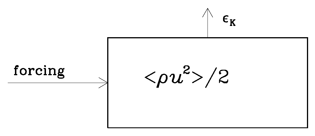
:1. Introduction
2. Energetics during the Emergence of Conductivity
3. Numerical Experiments with Different Temporal Conductivity Variations
3.1. Electromagnetic Waves and Their Suppression by Conductivity
3.2. Transition to the High-Conductivity Regime for Different Parameters
4. Cosmological Application Prior to Radiation Domination
4.1. Magnetic Fields in Cosmology
4.2. Use of Comoving Variables and Conformal Time
4.3. Inflationary Magnetogenesis
4.4. Continuous Version of the Generation Term
4.5. Energy Conversions during Reheating
5. Conclusions
Author Contributions
Funding
Institutional Review Board Statement
Data Availability Statement
Acknowledgments
Conflicts of Interest
References
- Moffatt, H.K. Magnetic Field Generation in Electrically Conducting Fluids; Cambridge University Press: Cambridge, MA, USA, 1978. [Google Scholar]
- Tobias, S.M. The turbulent dynamo. J. Fluid Mech. 2021, 912, P1. [Google Scholar] [CrossRef] [PubMed]
- Brandenburg, A. Magnetic Prandtl Number Dependence of the Kinetic-to-magnetic Dissipation Ratio. Astrophys. J. 2014, 791, 12. [Google Scholar] [CrossRef]
- Brandenburg, A.; Rempel, M. Reversed Dynamo at Small Scales and Large Magnetic Prandtl Number. Astrophys. J. 2019, 879, 57. [Google Scholar] [CrossRef]
- Mahajan, S.M.; Shatashvili, N.L.; Mikeladze, S.V.; Sigua, K.I. Acceleration of Plasma Flows Due to Reverse Dynamo Mechanism. Astrophys. J. 2005, 634, 419–425. [Google Scholar] [CrossRef]
- Field, G.B.; Carroll, S.M. Axions and Cosmic Magnetic Fields. arXiv 2023, arXiv:2307.05425. [Google Scholar] [CrossRef]
- Sharma, R.; Jagannathan, S.; Seshadri, T.R.; Subramanian, K. Challenges in inflationary magnetogenesis: Constraints from strong coupling, backreaction, and the Schwinger effect. Phys. Rev. D 2017, 96, 083511. [Google Scholar] [CrossRef]
- Brandenburg, A.; Sharma, R. Simulating Relic Gravitational Waves from Inflationary Magnetogenesis. Astrophys. J. 2021, 920, 26. [Google Scholar] [CrossRef]
- Alfvén, H. Existence of Electromagnetic-Hydrodynamic Waves. Nature 1942, 150, 405–406. [Google Scholar] [CrossRef]
- Brandenburg, A.; Enqvist, K.; Olesen, P. Large-scale magnetic fields from hydromagnetic turbulence in the very early universe. Phys. Rev. D 1996, 54, 1291–1300. [Google Scholar] [CrossRef]
- Christensson, M.; Hindmarsh, M.; Brandenburg, A. Inverse cascade in decaying three-dimensional magnetohydrodynamic turbulence. Phys. Rev. E 2001, 64, 056405. [Google Scholar] [CrossRef]
- Banerjee, R.; Jedamzik, K. Evolution of cosmic magnetic fields: From the very early Universe, to recombination, to the present. Phys. Rev. D 2004, 70, 123003. [Google Scholar] [CrossRef]
- Kahniashvili, T.; Tevzadze, A.G.; Brandenburg, A.; Neronov, A. Evolution of primordial magnetic fields from phase transitions. Phys. Rev. D 2013, 87, 083007. [Google Scholar] [CrossRef]
- Brandenburg, A.; Kahniashvili, T.; Tevzadze, A.G. Nonhelical Inverse Transfer of a Decaying Turbulent Magnetic Field. Phys. Rev. L 2015, 114, 075001. [Google Scholar] [CrossRef] [PubMed]
- Brandenburg, A.; Kahniashvili, T. Classes of Hydrodynamic and Magnetohydrodynamic Turbulent Decay. Phys. Rev. L 2017, 118, 055102. [Google Scholar] [CrossRef] [PubMed]
- Hosking, D.N.; Schekochihin, A.A. Cosmic-void observations reconciled with primordial magnetogenesis. arXiv 2022, arXiv:2203.03573. [Google Scholar]
- Silk, J. Cosmic Black-Body Radiation and Galaxy Formation. Astrophys. J. 1968, 151, 459. [Google Scholar] [CrossRef]
- Kolb, E.W.; Turner, M.S. The Early Universe; Avalon Publishing: New York, NY, USA, 1990; Volume 69. [Google Scholar]
- Brandenburg, A.; Enqvist, K.; Olesen, P. The effect of Silk damping on primordial magnetic fields. Phys. Lett. B 1997, 392, 395–402. [Google Scholar] [CrossRef]
- Kobayashi, T.; Afshordi, N. Schwinger effect in 4D de Sitter space and constraints on magnetogenesis in the early universe. J. High Energy Phys. 2014, 2014, 166. [Google Scholar] [CrossRef]
- Henriksen, R. Solar and Galactic Magnetic Halo Structure: Force-Free Dynamos? Galaxies 2019, 7, 53. [Google Scholar] [CrossRef]
- Brandenburg, A.; Ntormousi, E. Dynamo effect in unstirred self-gravitating turbulence. Mon. Not. R. Astron. Soc. 2022, 513, 2136–2151. [Google Scholar] [CrossRef]
- Brandenburg, A.; Jennings, R.L.; Nordlund, Å.; Rieutord, M.; Stein, R.F.; Tuominen, I. Magnetic structures in a dynamo simulation. J. Fluid Mech. 1996, 306, 325–352. [Google Scholar] [CrossRef]
- Brandenburg, A.; Nordlund, A.; Stein, R.F.; Torkelsson, U. Dynamo-generated Turbulence and Large-Scale Magnetic Fields in a Keplerian Shear Flow. Astrophys. J. 1995, 446, 741. [Google Scholar] [CrossRef]
- Pencil Code Collaboration; Brandenburg, A.; Johansen, A.; Bourdin, P.; Dobler, W.; Lyra, W.; Rheinhardt, M.; Bingert, S.; Haugen, N.; Mee, A.; et al. The Pencil Code, a modular MPI code for partial differential equations and particles: Multipurpose and multiuser-maintained. J. Open Source Softw. 2021, 6, 2807. [Google Scholar] [CrossRef]
- Gedalin, M. Linear waves in relativistic anisotropic magnetohydrodynamics. Phys. Rev. E 1993, 47, 4354–4357. [Google Scholar] [CrossRef]
- Durrer, R.; Neronov, A. Cosmological magnetic fields: Their generation, evolution and observation. Astron. Astrophys. Rev. 2013, 21, 62. [Google Scholar] [CrossRef]
- Subramanian, K. The origin, evolution and signatures of primordial magnetic fields. Rep. Prog. Phys. 2016, 79, 076901. [Google Scholar] [CrossRef]
- Neronov, A.; Vovk, I. Evidence for Strong Extragalactic Magnetic Fields from Fermi Observations of TeV Blazars. Science 2010, 328, 73. [Google Scholar] [CrossRef] [PubMed]
- Taylor, A.M.; Vovk, I.; Neronov, A. Extragalactic magnetic fields constraints from simultaneous GeV-TeV observations of blazars. Astron. Astrophys. 2011, 529, A144. [Google Scholar] [CrossRef]
- Broderick, A.E.; Chang, P.; Pfrommer, C. The Cosmological Impact of Luminous TeV Blazars. I. Implications of Plasma Instabilities for the Intergalactic Magnetic Field and Extragalactic Gamma-Ray Background. Astrophys. J. 2012, 752, 22. [Google Scholar] [CrossRef]
- Broderick, A.E.; Tiede, P.; Chang, P.; Lamberts, A.; Pfrommer, C.; Puchwein, E.; Shalaby, M.; Werhahn, M. Missing Gamma-ray Halos and the Need for New Physics in the Gamma-ray Sky. Astrophys. J. 2018, 868, 87. [Google Scholar] [CrossRef]
- Sironi, L.; Giannios, D. Relativistic Pair Beams from TeV Blazars: A Source of Reprocessed GeV Emission rather than Intergalactic Heating. Astrophys. J. 2014, 787, 49. [Google Scholar] [CrossRef]
- Alves Batista, R.; Saveliev, A.; de Gouveia Dal Pino, E.M. The impact of plasma instabilities on the spectra of TeV blazars. Mon. Not. R. Astron. Soc. 2019, 489, 3836–3849. [Google Scholar] [CrossRef]
- Adshead, P.; Giblin, J.T., Jr.; Scully, T.R.; Sfakianakis, E.I. Gauge-preheating and the end of axion inflation. J. Cosmol. Astropart. Phys. 2015, 2015, 34. [Google Scholar] [CrossRef]
- Adshead, P.; Giblin, J.T.; Scully, T.R.; Sfakianakis, E.I. Magnetogenesis from axion inflation. J. Cosmol. Astropart. Phys. 2016, 2016, 039. [Google Scholar] [CrossRef]
- Adshead, P.; Giblin, J.T.; Pieroni, M.; Weiner, Z.J. Constraining axion inflation with gravitational waves from preheating. Phys. Rev. D 2020, 101, 083534. [Google Scholar] [CrossRef]
- Ratra, B. Cosmological “Seed” Magnetic Field from Inflation. Astrophys. J. Lett. 1992, 391, L1. [Google Scholar] [CrossRef]
- Demozzi, V.; Mukhanov, V.; Rubinstein, H. Magnetic fields from inflation? J. Cosmol. Astropart. Phys. 2009, 8, 025. [Google Scholar] [CrossRef]
- Ferreira, R.J.Z.; Jain, R.K.; Sloth, M.S. Inflationary magnetogenesis without the strong coupling problem. J. Cosmol. Astropart. Phys. 2013, 2013, 004. [Google Scholar] [CrossRef]
- Kobayashi, T.; Sloth, M.S. Early cosmological evolution of primordial electromagnetic fields. Phys. Rev. D 2019, 100, 023524. [Google Scholar] [CrossRef]
- Sharma, R.; Subramanian, K.; Seshadri, T.R. Generation of helical magnetic field in a viable scenario of inflationary magnetogenesis. Phys. Rev. D 2018, 97, 083503. [Google Scholar] [CrossRef]
- Brandenburg, A.; He, Y.; Sharma, R. Simulations of Helical Inflationary Magnetogenesis and Gravitational Waves. Astrophys. J. 2021, 922, 192. [Google Scholar] [CrossRef]
- Subramanian, K. Magnetic fields in the early Universe. Astron. Nachr. 2010, 331, 110. [Google Scholar] [CrossRef]
- He, Y.; Roper Pol, A.; Brandenburg, A. Modified propagation of gravitational waves from the early radiation era. J. Cosmol. Astropart. Phys. 2023, 2023, 025. [Google Scholar] [CrossRef]
- Kronberg, P.P. Extragalactic magnetic fields. Rep. Prog. Phys. 1994, 57, 325–382. [Google Scholar] [CrossRef]
- Widrow, L.M. Origin of galactic and extragalactic magnetic fields. Rev. Mod. Phys. 2002, 74, 775–823. [Google Scholar] [CrossRef]
- Giovannini, M. The Magnetized Universe. Int. J. Mod. Phys. D 2004, 13, 391–502. [Google Scholar] [CrossRef]
- Kandus, A.; Kunze, K.E.; Tsagas, C.G. Primordial magnetogenesis. Phys. Rep. 2011, 505, 1–58. [Google Scholar] [CrossRef]
- Vachaspati, T. Progress on cosmological magnetic fields. Rep. Prog. Phys. 2021, 84, 074901. [Google Scholar] [CrossRef]


| Rapid Transits | Long Transits | |
|---|---|---|
| criterion | ||
| Lorentz work | ||
| heating | and |
| 1 | 3 | 2.5 | 2.45 |
| 2 | 5 | 4.5 | 4.47 |
| 4 | 9 | 8.5 | 8.49 |
| Set | k | Variable | ||||
|---|---|---|---|---|---|---|
| (i) | 10 | 1 | ||||
| (ii) | 10 | 0.1 | ||||
| (iii) | 1 | 1 | ||||
| (i) | 10 | 1 | ||||
| (ii) | 10 | 0.1 | ||||
| (iii) | 1 | 1 | ||||
| (i) | 10 | 1 | ||||
| (ii) | 10 | 0.1 | ||||
| (iii) | 1 | 1 | ||||
| (i) | 10 | 1 | ||||
| (ii) | 10 | 0.1 | ||||
| (iii) | 1 | 1 | ||||
| (i) | 10 | 1 | ||||
| (ii) | 10 | 0.1 | ||||
| (iii) | 1 | 1 | ||||
| (i) | 10 | 1 | ||||
| (ii) | 10 | 0.1 | ||||
| (iii) | 1 | 1 | ||||
| (i) | 10 | 1 | ||||
| (ii) | 10 | 0.1 | ||||
| (iii) | 1 | 1 | ||||
| (i) | 10 | 1 | ||||
| (ii) | 10 | 0.1 | ||||
| (iii) | 1 | 1 |
Disclaimer/Publisher’s Note: The statements, opinions and data contained in all publications are solely those of the individual author(s) and contributor(s) and not of MDPI and/or the editor(s). MDPI and/or the editor(s) disclaim responsibility for any injury to people or property resulting from any ideas, methods, instructions or products referred to in the content. |
© 2023 by the authors. Licensee MDPI, Basel, Switzerland. This article is an open access article distributed under the terms and conditions of the Creative Commons Attribution (CC BY) license (https://creativecommons.org/licenses/by/4.0/).
Share and Cite
Brandenburg, A.; Protiti, N.N. Electromagnetic Conversion into Kinetic and Thermal Energies. Entropy 2023, 25, 1270. https://doi.org/10.3390/e25091270
Brandenburg A, Protiti NN. Electromagnetic Conversion into Kinetic and Thermal Energies. Entropy. 2023; 25(9):1270. https://doi.org/10.3390/e25091270
Chicago/Turabian StyleBrandenburg, Axel, and Nousaba Nasrin Protiti. 2023. "Electromagnetic Conversion into Kinetic and Thermal Energies" Entropy 25, no. 9: 1270. https://doi.org/10.3390/e25091270
APA StyleBrandenburg, A., & Protiti, N. N. (2023). Electromagnetic Conversion into Kinetic and Thermal Energies. Entropy, 25(9), 1270. https://doi.org/10.3390/e25091270