Article

Evaluation of Weakening Characteristics of Reinforced Concrete Using High-Frequency Induction Heating Method

1
Department of Architecture Engineering, Songwon University, Gwangju 61756, Korea
2
Department of Mechanical and Shipbuilding Convergence Engineering, Pukyong National University, Busan 48547, Korea
*
Author to whom correspondence should be addressed.
Appl. Sci. 2021, 11(12), 5402; https://doi.org/10.3390/app11125402
Submission received: 28 April 2021 / Revised: 4 June 2021 / Accepted: 7 June 2021 / Published: 10 June 2021

Abstract

:
To increase the quality of recycling, a new demolition technique is required that can work in parallel with existing crushing methods, which use large equipment with high crushing efficiency. Moreover, the efficient collection of the remains from the fractional dismantling method needs to be considered based on its procedure, and the technology for partial dismantling that is efficient in remodeling, maintenance, and reinforcement has to be developed. In this study, the temperature-increasing characteristics of rebars inside ferroconcrete with respect to their arrangement was investigated by partial rapid heating through high-frequency induction heating. Based on this, the chemical and physical vulnerability characteristics of ferroconcrete due to the thermal conduction generated on the rebar surface and the cracks caused by the thermal expansion pressure of the rebar were verified. In addition, the objective of this study was to verify the applicability of the technology by specifying the vulnerability range of ferroconcrete based on the heating range with adequate consumption of energy.

1. Introduction

Reinforced concrete structures are frequently used in bridge engineering owing to their excellent mechanical properties and durability [1,2,3]. However, certain inevitable damage or defects such as concrete cracks, voids, loss of pre-stress, rebar corrosion, and other defects are bound to occur in bridge structures during their construction and service. These internal defects threaten the safety and durability of the structure as they increase in severity with time and are affected by environmental conditions. Steel corrosion is the first major factor affecting the durability of concrete structures [4,5,6], and it is an extremely complicated process.
Conducting nondestructive investigation to assess steel corrosion in a reinforced concrete bridge throughout its life cycle is necessary because internal corrosion is not visible from the outside. Extensive research has been conducted on this matter, which led to many nondestructive testing methods being proposed [7], namely the analytical method [8], half-cell potential method [9,10], resistance probe method [11], ray method [12], ultrasonic detection [13], and optical fiber sensing technology [14]. Although these methods have significantly improved the detection of steel corrosion, certain restrictions exist for their widespread use. For example, the analytical method relies on a reasonable and reliable predictive model for assessing steel corrosion [15], while the electrochemical method can calibrate the corrosion rate but cannot detect the corrosion quantity of the steel bar [16,17]. Thus, a more effective and convenient technology for corrosion detection is urgently required. The eddy current thermography method is a nondestructive testing technology that has been developed in recent years [18] and is based on the principles of electromagnetic induction and infrared radiation. When a conductor is placed in an alternating electromagnetic field, an eddy current is induced, which causes heat dissipation. The surface temperature of the conductor can be recorded using an infrared camera. The heating efficiency is controlled by the material characteristics of the conductor; therefore, the characteristics of the defects in the object can be assessed by analyzing the temperature variations.
Many researchers have conducted research on detecting structural defects [19,20,21], pipe leakages [22], and cracks [23]. Further, some research groups have investigated corrosion in steel bars based on eddy current thermography, and found that the temperature of a steel bar is dependent on the degree of corrosion of the specimens [24,25,26,27]. However, many other factors can influence the thermal properties of steel bars, such as the depth of the concrete layer, the diameter of the steel bar, and the humidity of concrete. These factors can affect the ability of detecting corrosion in reinforcement structures and the lack of research regarding their influence limits the application of these methods to quantitatively determine the degree of corrosion in steel bars.
Heat is primarily produced by applying high-frequency magnetic fields. Detection methods are thus classified according to the principle of heat generation and application. Typically, radio-frequency heating can be classified as induction or dielectric heating. Induction heating uses an eddy current generated [28,29,30] when a high-frequency magnetic field is applied to a conductor such as a metal. Conversely, the dielectric heating method uses the dielectric loss caused by a high-frequency current applied to the dielectric medium to generate heat [31,32].
This weakening mechanism has already been applied in the manufacturing of recycled aggregates as well as for removing deposited mortar on the surface of aggregates. However, heating methods using external heat sources have low energy efficiency, which results in high energy consumption and greenhouse gas generation through regeneration processes [33,34,35].
In contrast, dielectric heating can achieve uniform internal heating and, if necessary, the location of the electric field can be specified [36,37]. However, the dielectric constant of a heated object may vary significantly during heating. Further, because dielectric heating requires a higher frequency power supply than induction heating, power converters such as inverters are required [38]. Therefore, dielectric heating systems are expensive, and there is a risk of inductive and radio wave interferences due to the harmonic waves generated by power converters. To avoid the inductive failure of the power supply system, the supply line providing power to the dielectric heating furnace and other power supply systems are kept independent, and an active filter is also used [39]. Furthermore, to overcome the possible interference with other radio devices, a power source in a frequency band provided exclusively for dielectric heating is used. However, owing to problems associated with high frequencies (short wavelengths) and the required equipment, the efficiency of use for dismantling structures is relatively poor compared to induction heating methods [40].
In this study, a general-purpose reinforcement utilized for reinforced concrete among metal materials was employed as a conductive resistor for high-frequency induction heating, and was used as a mechanism to weaken concrete via thermal conduction of heated reinforcing steel. In the case of high-frequency induction heating, the internal reinforcement, that is, the heated object, generates heat by itself and thus increases the energy density of the reinforcement inside the reinforced concrete much more effectively than indirect heating using hydrogen. Further, for reinforced concrete members, the surface temperature of reinforced concrete increases owing to heat-sensitive conductive resistance to high-frequency induction heating, resulting in increased heat being applied to the surface temperature of the reinforced concrete. In addition, separation of concrete enclosing reinforcing bars by heating concrete on the surface of the reinforcing bar and dehydrating and weakening the cement paste (the main component of concrete) is possible. Furthermore, in induction heating, local heating is possible. Moreover, increasing the temperature of cement-based substances is comparatively economical because of their excellent thermal efficiency. However, as mentioned in the previous paragraphs, various variables related to the maximum power cost exist, such as the surface area and heating distance of the reinforcing steel, and the concrete is expected to undergo various internal structural changes such as changes in density due to temperature variations.
In this study, we examine the characteristics of concrete using temperature distributions and trends consistent with those applied in previous research to the same type of reinforcement, arrangement of reinforcing bars, and heating distances. For a particular reinforced concrete specimen featuring a single reinforced bar, the basic characteristics were examined using high-frequency induction heating. In high-frequency induction heating, the increase of temperature with time depends on the changes in eddy current and current density caused by the joining method and bar arrangement. Furthermore, the mechanical, physical, and chemical properties of concrete against the actual fragility of reinforced concrete members due to high-frequency induction heating were examined to determine the fragility properties of heated concrete.

2. Deconstruction Model of Reinforced Concrete Using High-Frequency Induction Heating

2.1. Reinforcing Bar Characteristics at High Temperatures

2.1.1. Density and Specific Heat

Most studies [3,4,5,9,10,11] reported that reinforcing bars do not exhibit significant changes in density due to changes in temperature, thus, it was assumed that the density (ρs) of the reinforcing bars is constant. The formulas for the specific heat of steel (Cc) as a function of temperature proposed in the Eurocode 2 [41] were used and are reported herein as Equations (1)–(4). The specific heat reaches a maximum value of 5000 J/kg∙K at 735 °C.
C c = 425 + 0.773 T 1.69 × 10 3 T 2 + 2.22 × 10 6 T 3   for   20   ° C < T 600   ° C
C c = 666 13,002 T 738   for   600   ° C < T 735   ° C
C c = 545 + 17,820 T 731   for   735   ° C < T 900   ° C
C c = 650   for   900   ° C < T 1200   ° C
However, in the temperature analysis, density and specific heat are treated as one variable referred as the heat capacitance (ρs Cs). The analytical model for the heat capacity of the reinforcing steel proposed by the ASCE (American Society of Civil Engineering) [42] are expressed via Equations (5)–(8).
ρ s   Cs = 0.004 T + 3.3 × 10 6   for   0   ° C T 650   ° C
ρ s   Cs = 0.068 T 38.3 × 10 6   for   650 T 725   ° C
ρ s   Cs = 0.086 T 73.35 × 10 6   for   725   ° C T 800   ° C
ρ s   Cs = 4.55 × 10 6   for   T 800   ° C
The unit of heat capacity is J/(m3·°C).

2.1.2. Thermal Conductivity

The thermal conductivity of reinforcing bars depends on the type and proportion of alloy elements as well as the hot working process [27,36,37]. The difference in thermal conductivity in different types of reinforcing bars is significant, but the range of thermal conductivity narrows as the temperature increases, with stability attained at 1000 °C [39,40]. Figure 1 shows the thermal conductivity according to the type of reinforcing bar used. It is evident that the relationship between the thermal conductivity Ks and the temperature of the reinforcing steel increased to approximately 900 °C. The analytical model for the temperature distribution proposed by Lie’s model [43,44,45,46] and the American Society of Civil Engineering [42] are expressed in Equations (9) and (10).
K s = 0.022   T + 48   W / m · ° C   for   0 T 900   ° C
K s = 28.2   W / m ° C   for   T 900   ° C
Eurocode 2 [41] proposes linear approximations such as Equations (11) and (12) for most structural steel materials.
K s = 24 3.33 × 10 2 T   for   20 T 800   ° C
K s = 27.3   for   800 < T 1200   ° C

2.2. Characteristics of Concrete at High Temperature

2.2.1. Thermal Conductivity of Concrete

The thermal conductivity of concrete varies depending on the compounding ratio, density, properties of the aggregate, moisture content, and cement type. Concrete thermal conductivity typically ranges from 2.5 to 3.0 kcal/mh°C. According to Harmathy [48], moisture is less than 100, which increases the thermal conductivity of ordinary concrete, however, Schneider [49] reported that the increase in internal temperature of ordinary concrete exhibited a gradual decrease in all temperature ranges. The thermal conductivity model formula for ordinary concrete presented by ENV 1994-1-2 and ECCS is expressed in Equation (13) [50].
K c = 2.0 0.24 T 120 + 0.012 ( T 120 ) 2 ( × 0.86   kcal hm ° C )

2.2.2. Vulnerability Characteristics of Concrete at High Temperatures

In concrete, 60–70% of cement hydroxide is composed of C-S-H gel, and 20–30% calcium hydroxide (Ca(OH)2), which evaporates free water in capillary voids at approximately 100 °C by heating, and thus decomposes the gel and calcium hydroxide at ≥180 and ≥700 °C, respectively. Because the concrete matrix consists of cement hydride, adsorbent water, capillary water in pores, gel water, and free water, high temperatures act as an important variable affecting the physical properties of concrete, which are greatly influenced by the cement type, formulation, and aggregate used. However, compression strength does not decrease significantly to 200 °C compared to the pre-heating strength [51,52]. Figure 2 shows the effects of cement-hardened bodies and aggregate temperature. As shown in Figure 2, it is possible to rapidly heat the internal rebar inside the ferroconcrete because the energy density is much higher in this method compared with ohmic heating and microwave heating methods based on combustion.

3. Experimental Considerations

3.1. Vulnerability of Single Reinforced Concrete to High-Frequency Induction Heating

3.1.1. Experimental Factors and Levels

We manufactured reinforced-concrete and conducted an experiment using a high-frequency induction heating system. The purpose of this study is to evaluate the temperature rise, and characteristics along with the vulnerability characteristics of concrete by induction heating.
Further, based on the conditions of concrete blending and moisture content, the distance condition for internal reinforcing steel was calculated using the cover thickness of concrete, and a reinforced concrete laboratory with different cover thicknesses was prepared. Furthermore, a change was added to the output amount, an appropriate output suitable for each coating thickness was considered, and a standard experiment under each condition was established. Thereafter, a relative evaluation was performed on the residual strength and vulnerability characteristics of concrete. The experimental levels are shown in Table 1, Table 2, Table 3.

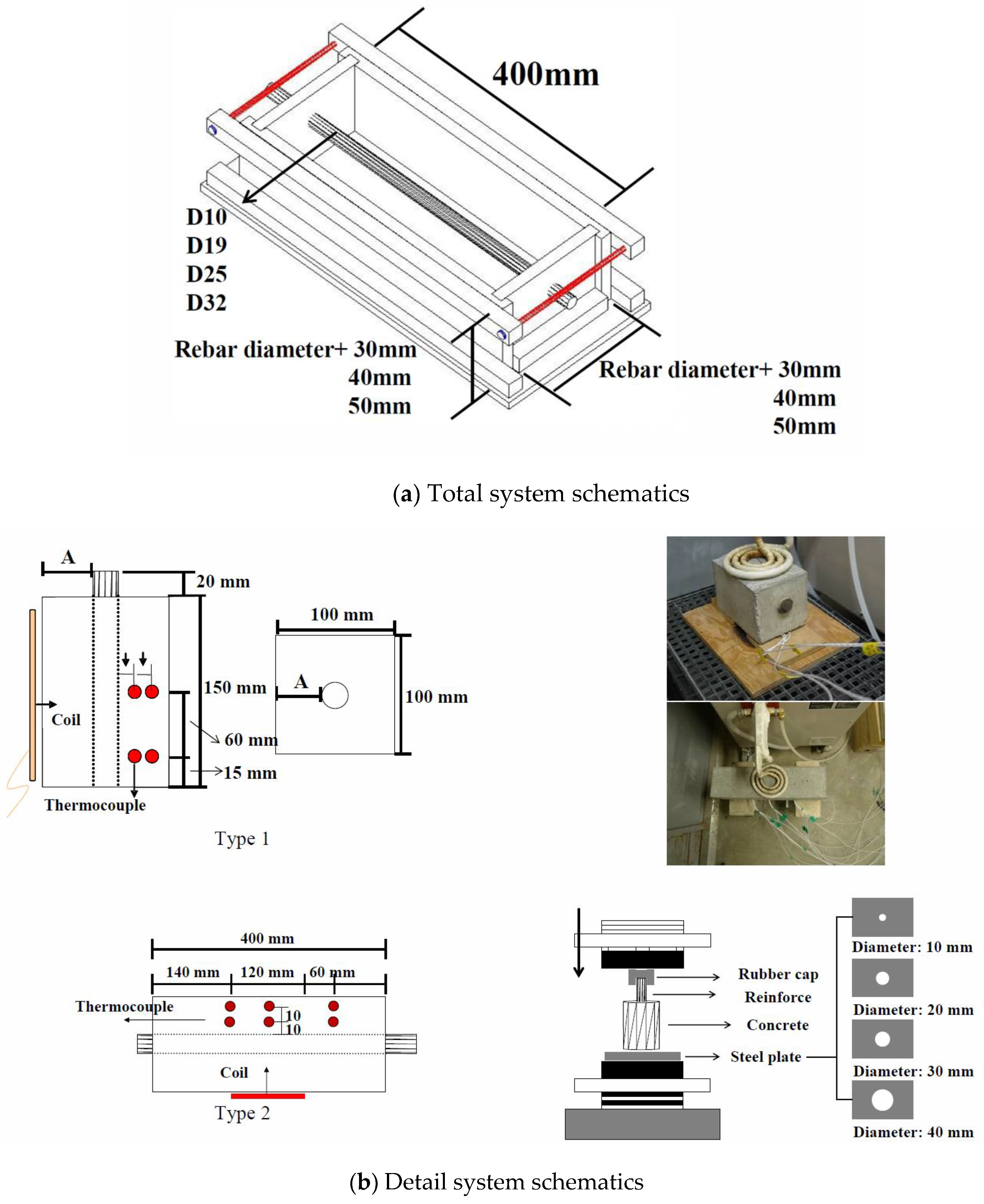
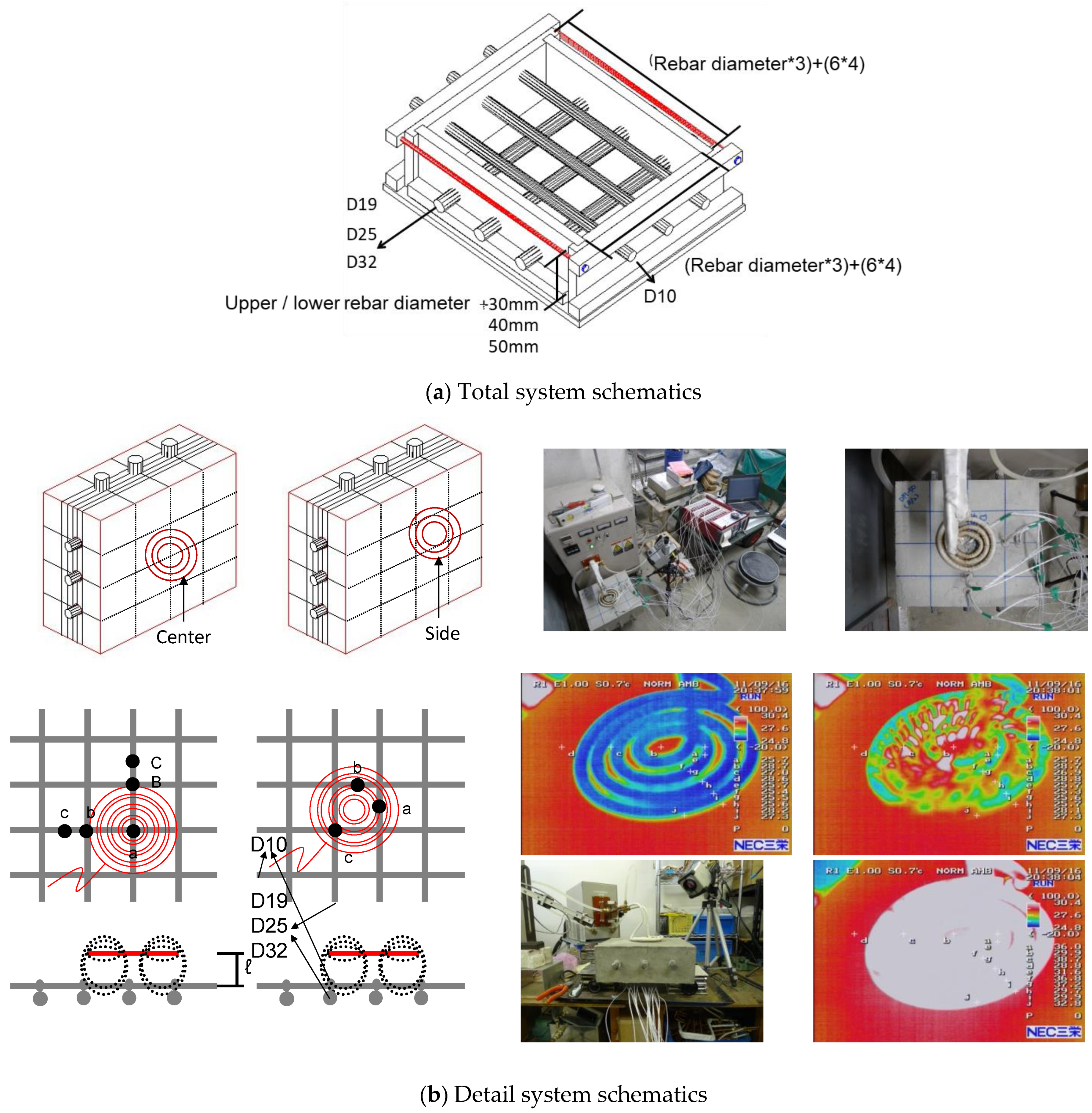
3.1.2. Manufacturing and Testing Methods of Induction-Heating Specimens

In this experiment, a test specimen wherein one deformed 180 mm long reinforcing bar was buried in 100 × 100 × 150 mm of concrete (W/C = 50%) was manufactured and heated via induction heating. Subsequently, temperature measurement of the reinforced concrete was performed by a thermocouple together with adhesion strength measurement via reinforced bar press testing.
Five combinations of thickness and cover thickness of the reinforcement were used: D10–30, D19–20, D19–30, D19–40, and D25–30 mm. For the punching test, three specimens under similar conditions were prepared and tested.
A beam-type reinforced concrete experiment with a coating thickness of 30, 40, 50 mm was manufactured by cutting reinforcing bars of D10, D19, D25, D32 into 430 mm sizes, and the characteristics of temperature rise and temperature distribution based on water binder, coating thickness, reinforcing bar type and frequency used. In the case of D19 reinforcing bars, experiments were conducted separately under air-dried and absolutely dry conditions. For each condition, a crack experiment was conducted using the remaining adhesion strength and thermal conduction before and after rebar heating.
For D10, samples were collected before and after heating, component analysis and pore structure changes were measured, vulnerability characteristics due to rapid heating were evaluated, and the recovery rate of rebars was evaluated using separated rebars.
The rebar drawing experiment was performed by producing three specimens with the same conditions for each combination. The rebars of D10, D19, D25, and D32 were cut in lengths of 430 mm, and the beam-shaped ferroconcrete specimens were then produced by setting the sheath thickness to 30, 40, and 50 mm. The production details for each specimen are shown in Figure 3. Temperature increase characteristic and temperature distribution characteristic were investigated according to the water-bonding material ratio, sheath thickness, rebar type, as well as the change in frequency used.

3.2. Experimental Results and Considerations

3.2.1. Temperature Characteristics of Single Reinforced Concrete by High-Frequency Induction Heating

(1)
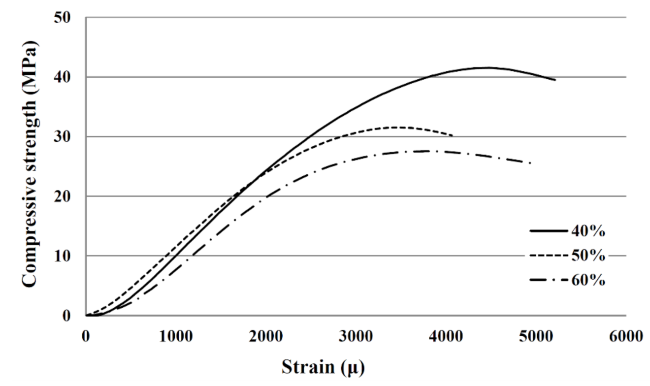
Compression Strength by Preparation
Test specimens were produced for different concrete compositions because it was hypothesized that the temperature increase and vulnerability characteristics would vary according to the water–cement ratio. The compression strength test for the material aged of 28 days was conducted as shown in Figure 4 per each specimen and since then, an evaluation with respect to the vulnerability characteristics was performed with high frequency induction heating. The compression strength specimens were cured under the air dry condition in order to account for the climatic conditions of the site.
(2)
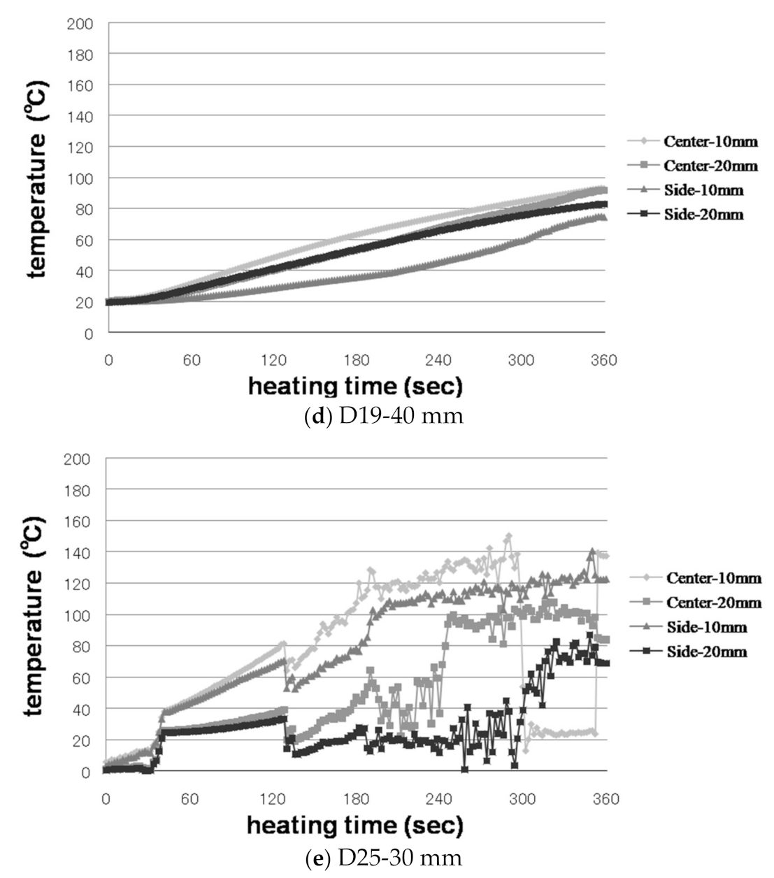
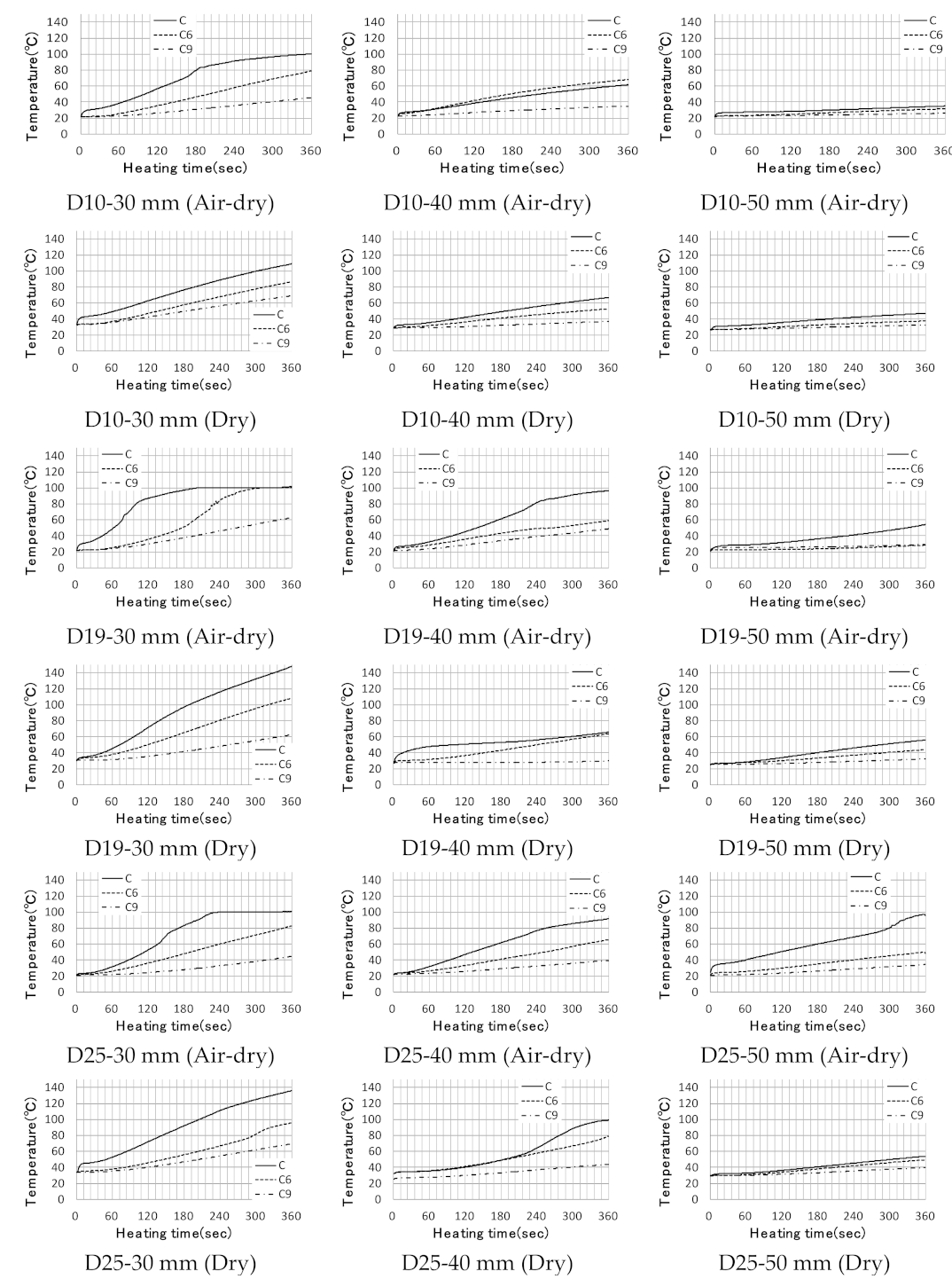
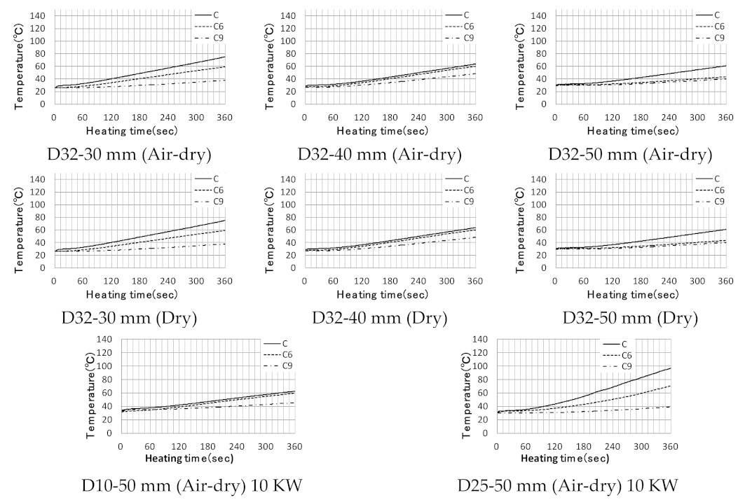
Increasing Temperature Characteristics
Figure 5 shows the increase of temperature with time for the concrete around the reinforcing bars using heat transfer pairs.
In the legend, the center is at the middle of 150 mm concrete specimen. A 75 mm portion has been indicated, and a 15 mm portion from the lower end of the specimen has also been indicated. In addition, 10 and 20 mm in the legend represent the distance from the surface of the reinforcing bar in the test body to the heat transfer pair.
In the case of heating at 6 kW for 360 s, the temperature change of the concrete due to the thermocouples was measured at 10 and 20 mm from the center of the rein and end of the reinforcement, respectively.
As a result of induction heating, the temperature increases in the order of the reinforcement center at 10 mm, end 10 mm, center at 20 mm, and end 20 mm, with the temperature difference between 10 and 20 mm from the reinforcement center being 46 to 90 °C.
As shown in Figure 5d, when the distance from the heating coil in the test specimen using D19 was 40 mm, the temperature difference between 10 and 20 mm from the center of the reinforcement was weak; a temperature difference of 74–83 °C occurred at the end, and a slight difference occurred compared to the center; however, the difference between the maximum and minimum temperatures was within 30 °C, and it was judged that there was no significant effect on concrete heat conduction.
The maximum temperature of reinforcement for D10 was 510 °C at the center of the reinforcement at a distance of 30 mm for 360 s, but the maximum temperature of concrete 10 mm away from the center of the reinforcement surface was 106 °C, when the reinforcement inserted into the concrete was heated, as shown in Figure 5a. Furthermore, for D19 and D25, the maximum temperatures of heating only the reinforcing steel were 651 and 613 °C, respectively, but when the reinforcing steel inserted into the concrete was heated, as shown in Figure 5c,e, the maximum temperatures were 171 and 139 °C, respectively.
The heat conduction characteristics of concrete change according to the internal moisture content. When high-frequency induction heating is used, the free water inside the concrete evaporates because of the rapid heating of the reinforcing steel; therefore, in this experiment, 450 mm of reinforced concrete was tested in air-dried and absolute-dried conditions. Four types of reinforcing steel, D10, D19, D25, D32, having coating thicknesses of 30, 40, and 50 mm were considered, and the temperature of a 10 mm-thick layer from the surface of the internal reinforcing steel was measured, as shown in Figure 6.
The difference in temperature between air-dry and absolute-dry conditions was 45 °C, and the difference in temperature between the dry conditions was measured high. Further, the difference is evident in the D19 and D25 experiments with high heating efficiency. Considering 40 mm coating thickness, the temperature difference between the two laboratories with high heating efficiency was evident, but D10 and D32 had relatively low heating efficiency, which was not significant. Further, for coating thickness of 50 mm, the temperature difference was not large. A relatively uniform rise curve in dry air compared to the gradient of temperature rise curve in dry air was observed. Furthermore, for the air-dried conditions, gel water evaporated for 80 °C or higher, thus the effects of this may cause an irregular temperature rise curve. Figure 6 shows the temperature rise characteristics of the reinforced concrete by induction heating.
In the case of a 5 kW heating power with a coating thickness of 50 mm or greater, the efficiency decreased sharply owing to the penetration characteristics of high-frequency induction heating. However, the temperature rise was small in the case of 10 kW heating power. For D10, however, the temperature increased to 60 °C, showing no significant difference from the 5 kW case, which seems to be due to a decrease in efficiency owing to a decrease in cross-sectional area in the magnetic field. Figure 6 shows the results of the 10 kW experiment.

3.2.2. Physical and Mechanical Properties of Single Reinforced Concrete by High-Frequency Induction Heating

(1)
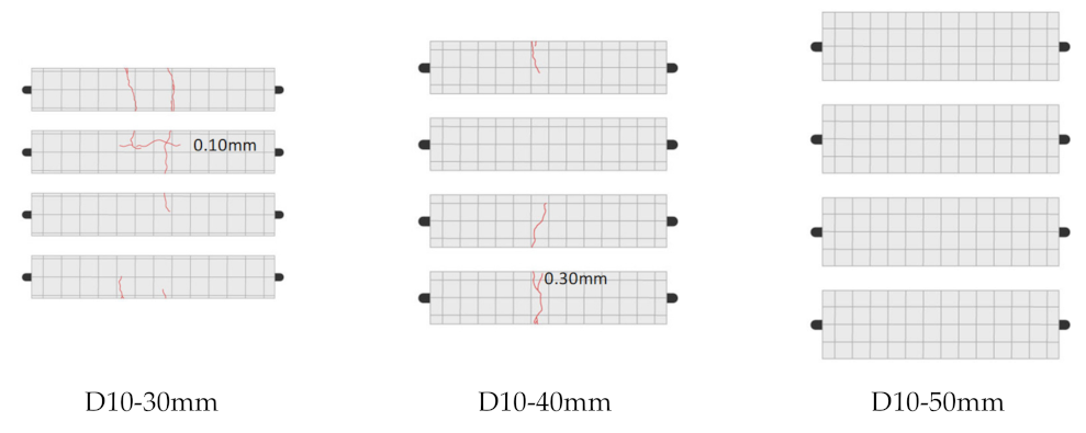
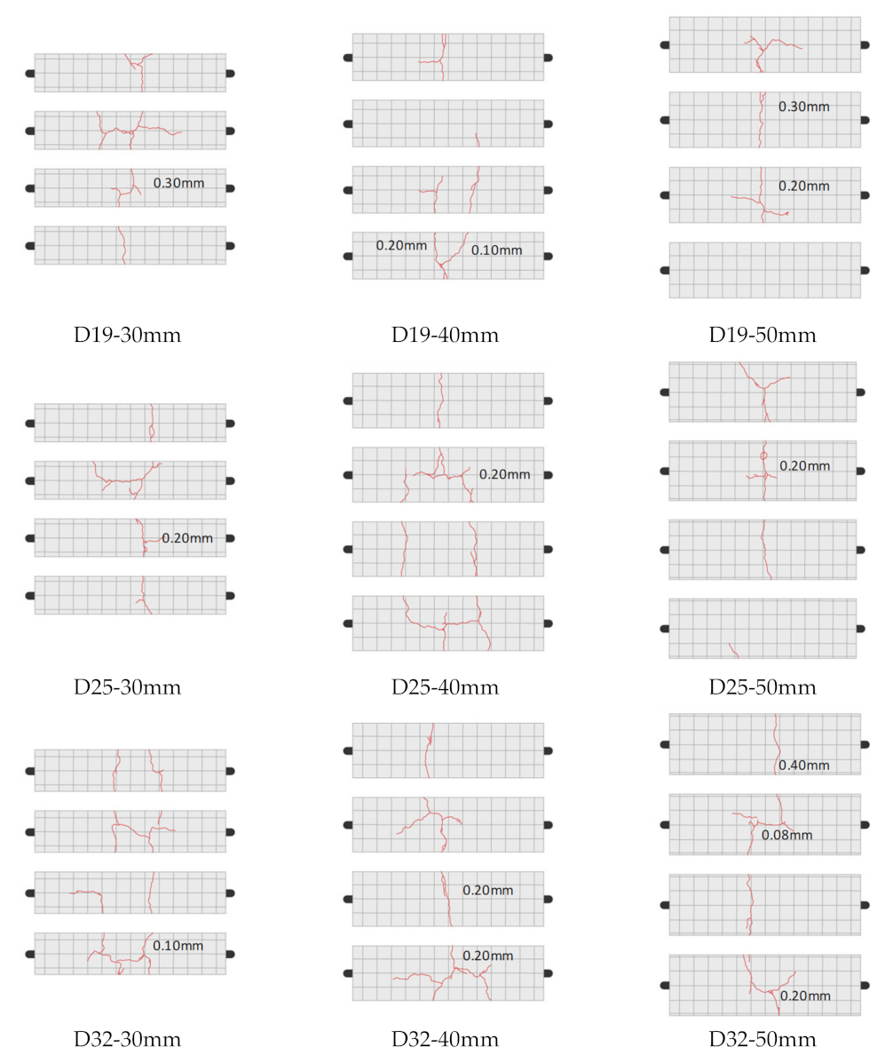
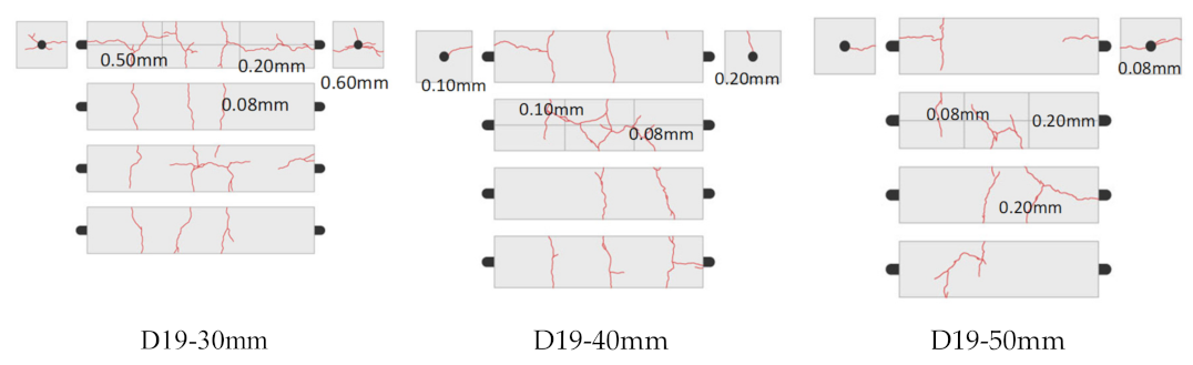
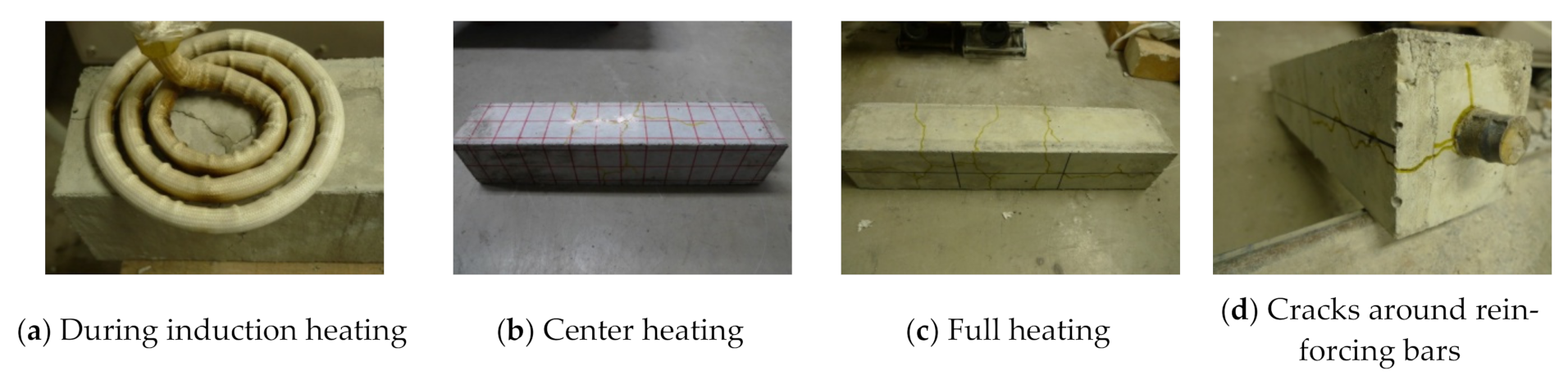
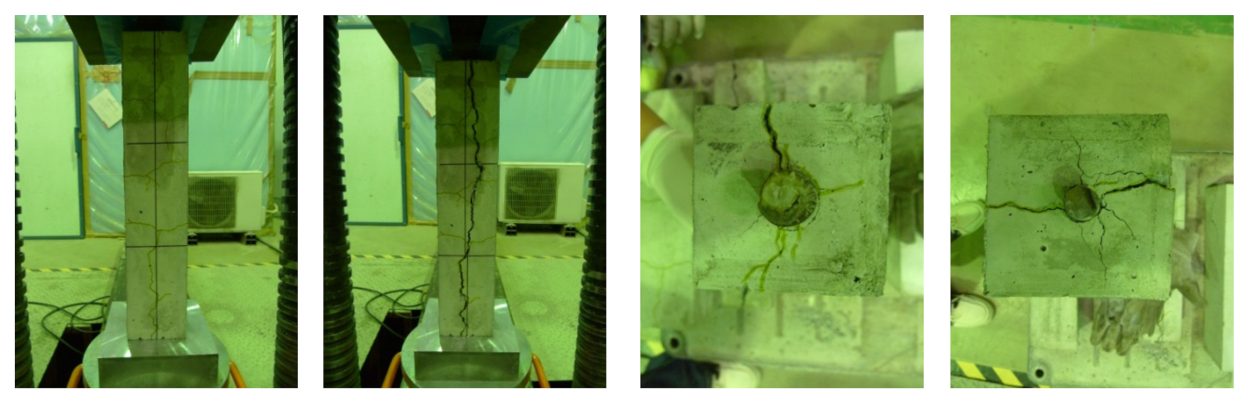
Cracks in Reinforced Concrete
(a)
Experiment Summary
Reinforced concrete structures deteriorate in performance due to high heat and constant heating, which results in cracks. Concrete deteriorated by high temperature is mostly repaired when hydrated after cooling, but when heated at 500 ℃ or higher it is damaged.
For reinforcing steel, the coefficient of thermal expansion from room temperature to 100 °C can be considered as 1 × 10⁻⁵ °C1, as shown in Table 4. The coefficient of thermal expansion increases sequentially when the temperature increases beyond that, and is approximately 0.12 × 10⁻⁵ °C−2 from 100–200 °C.
Therefore, cracks are predicted to occur in the reinforced concrete owing to thermal expansion by induction heating, and the purpose of this section is to determine the crack shapes and to use them as input data to predict the effect of cracks on the weakening of reinforced concrete and steel.
(b)
Experimental Results and Considerations
In the case of single reinforced concrete, D10, D19, D25, and D32 reinforcing bars were used, and the cover thicknesses were manufactured at 30, 40, and 50 mm. Furthermore, for high-frequency induction heating, a heating coil was positioned in the center of the test specimen with a frequency of 5 kW and heated for 360 s. Figure 7 and Figure 8 shows the crack formed due to the high-frequency induction heating.
In the case of the 30 mm and 40 mm laboratories close to each other, the cracks occurred on the surface of the specimen within 30 s after heating, while the 50 mm specimen cracked within a min of heating, however, the D10 specimen did not.
If the cover thickness was 30 mm, cracks occurred along the reinforcing bar and vertical directions on all specimens, and cracks occurred in the concrete within the coil diameter; further, for a cover thickness of 40 mm, cracks occurred in all test specimens except the one using D10 reinforcing steel. In contrast, for 50 mm cover thickness, cracks occurred in specimens other than D10 reinforcing bars within one min, but occurred in the form of a single crack from the reinforcing bar to the concrete surface. For D10 reinforcing bars, the size of the thermal expansion pressure is smaller owing to the reduction in cross-sectional area compared to other reinforcing bars, thus the changes in the occurrence of cracks appeared differently.
For distances of 30 and 40 mm with high heating efficiency, the concrete is considered suitable for peeling after heating owing to the occurrence of both cracks, and it can thus be dismantled selectively through local heating. Furthermore, it was determined that even a single crack affects the restraint stress reduction of the rebar.
When using D19 reinforcement, the entire surface of the test specimen was heated sequentially along the length direction of the 400 mm test specimen, and cracks occurred on the vertical surface with further cracks created along the direction of the reinforcing bar, and the results indicated that the cracks developed along the reinforcement perimeter in the upper part where the reinforcement was exposed.
Therefore, continuous heating has a significant effect on the lowering of the binding stress on the strength of the reinforcing steel, which results in a significant effect on the separation of reinforcing steel and concrete.
Furthermore, the crack width was reduced by reducing the temperature inside after heating compared to the width during heating as shown Figure 9; the crack phenomenon shown in this section indicates the width of the crack after heating.
(2)
Temperature-Induced Vulnerability
(a)
Vulnerability due to Changes in Void Volume
Cement-based substances are porous bodies consisting of capillary, gel, and free water present in the pores of the hydrates.
A 1 mm-thick sample was taken from the surface of the reinforcing steel to the surface of the concrete using the temperature distribution of the reinforcing steel as a reference for the heating range; thereafter, as shown in Figure 10, the air gap structure change due to induction heating of single reinforced concrete was measured using the mercury press fitting method; a high peak of approximately 0.1 μm was observed, and owing to an increase in temperature due to thermal conduction from reinforcing bars the peak of pore size distribution moved toward a larger pore size.
In each specimen, the number of voids increased upon heating. A similar tendency was observed regardless of the water binder ratio, and the increase in the number of voids varied slightly with the type and preparation conditions of the specimens. However, it is typical for the integrated voids to increase with the increase in heating temperature, and the accumulated porosity is also gradually increased by heating according to the water bonding material ratio.
Considering a 40% water binder ratio, voids of 0.05 μm and below were decreased by induction heating, voids of 0.1 μm increased rapidly, while the integrated voids gradually increased. In contrast, for water binder ratio of 50 and 60%, gaps of 0.05 μm and below increased, while gaps of 0.1 μm and greater increased considerably.
Typically, hydrates comprising concrete yield different volume ratios depending on the hydration state of the cement and the water–binder ratio. A small water–binder ratio results in larger capillary water and porosity as the number of capillary tubes is increased. For a hardened cement, approximately 60–70% of the solid portion is a C-S-H-based hydrate, with approximately 20–30% being calcium hydroxide; although capillary water differs according to the volumetric ratio of the water binder, the increase in porosity is almost the same because the gel water evaporates at almost the same volume ratio.
An increase in porosity can be interpreted as being a result of water evaporation, dehydration of hydrate and alteration temperature. Owing to such an increase in porosity, the cement-hardened body becomes porous, which affects the physical properties of concrete, and thus the compressive strength reduction and weakening properties.
Furthermore, an increase in the voids in induction heating is a result of the generation of fine cracks in concrete, dehydration of water from gel and capillary voids, and decomposition of S-C-H hydrates and calcium hydroxide chemically bonded to evaporate the bonded water.
(b)
Chemical Vulnerability Characteristics
Introduction: Concrete is a material composed of aggregates, cement, and water. After hydration reactions, 60–70% of the mass is composed of C-S-H(CaO-SiO2-H2O) gel, and the remaining 20–30% is calcium hydroxide (Ca(OH)2).
When concrete is exposed to high temperatures, the chemical and physical structures change, resulting in the dehydration of calcium hydrate and thermal expansion of the aggregates, which cause cracks in the concrete at temperatures above 300 °C.
Calcium hydroxide (Ca(OH)2) in the hardened cement body is disassembled at 530 °C, while CSH gel, which has a large effect on the physical properties of concrete, is disassembled at temperatures of 600 °C or higher. Further, concrete melts at a temperature of 1150 °C or higher [53].
Concrete is a porous structure composed of hardened cement bodies and voids, which contain aggregate, cement, chemically bonded water, and gel water, and the voids are filled with free water and air.
The moisture content change in concrete is defined as free water moving through voids, and the free and gel waters vaporized between room temperature to 105 °C. In addition, the release of chemically bonded water starts at 105 °C or higher and is completely released at 850 °C [54].
However, the thermal conductivity of ordinary concrete depends on the type and preparation of the aggregate. At room temperature, the thermal conductivity exceeds 2.0 kcal/mh °C, but decreases with temperature rise, and at 600 °C or higher, it becomes approximately 1.0 kcal/mh °C. Although thermal deformation for generating thermal stress in concrete is affected by the aggregate, it expands to 600–800 °C at room temperature, and the coefficient of thermal expansion is approximately 1.0 × 10⁻⁵–1.5 × 10⁻⁵ °C−1. Furthermore, the strength of concrete decreases at high temperatures, which also varies depending on the type of aggregate and the stress conditions, but typically falls to 50–60% at room temperature at 500 °C or greater, and even if moisture is replenished after cooling, it is difficult to recover strength because the cracks caused by the difference in the coefficient of thermal expansion between the cement paste and aggregate affects the internal structure.

4. Experimental Method

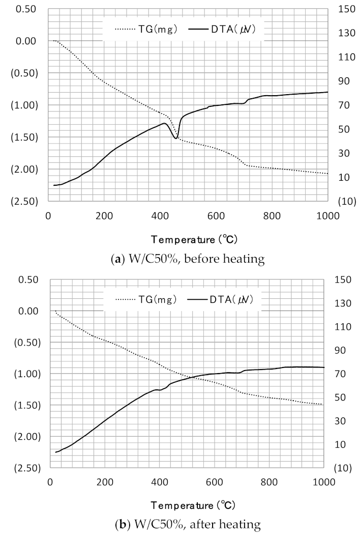
4.1. Simultaneous Thermal Weight/Differential Thermal Analysis (TG-DTA)

The thermocouple measures the temperature difference between the sample and the inert reference material. Thereafter, a temperature program was used for one sample, and the mass change of the sample was measured as a function of time and temperature.
The results (Table 5) measured by TG/DTA can be set to three temperature zones by a curve: Region 1 is a 100–300 °C region, and C-S-H is a region where etringite decomposes. In the temperature zone, C-S-H loses water due to the CaO-SiO2 ratio and thus decomposes. In Region 2, calcium aluminate silicate hydrate and calcium aluminate hydrate are decomposed in the range of 290–350 °C. Region 3 is a 450–510 °C region and a decomposition region of Ca(OH)2. The endothermic section appearing at approximately 700 °C refers to the decomposition of CaCO3 in the hydrate [55].
Concrete powder (40–50 mg) sampled around the heated reinforcing bars was placed in a platinum container, and TG/DTA was simultaneously performed from 25 °C to 1000 °C. The temperature rise rate was set at 20 °C/min from 50 °C to 400 °C, and then at 10 °C/min from 400 °C to 1000 °C. Furthermore, nitrogen gas was used as a buffer gas while alumina powder was used as a reference sample.

4.2. Experimental Results and Considerations

As shown in Figure 11, the temperature section where rapid heat absorption is observed on the DTA curve is 440–480 °C, and this section is determined to be the section where Ca(OH)2 generated by hydration shows phase change and evaporation. As shown in the figure, the evaporation of capillary and gel waters generated heat absorption zones up to 200 °C, and decomposition of Ca(OH)2 generated strong heat absorption peaks within range of 440–480 °C, which greatly reduced the weight of the sample; further, another endothermic reaction occurred due to the decomposition of calcite (CaCO3) at 700 °C.
Thus, for induction heating based on the above results, it was determined that the endothermic reaction of calcium hydroxide generated at 520 °C on the surface of the reinforcing steel was completely advanced, and it was determined that high heat between 500–650 °C was conducted in a state where there was almost no decrease in weight change, although an endothermic reaction occurred due to the decomposition of calcite.

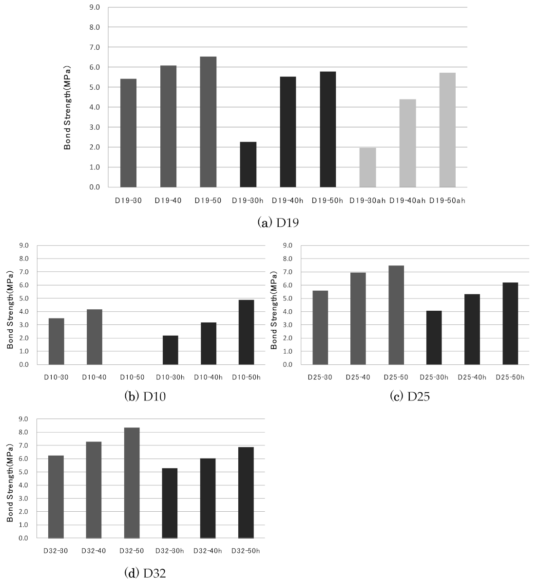
4.3. Remaining Strength of Reinforcement

(a)
Experiment overview
Reinforced concrete structures efficiently combine and integrate different materials of reinforcing steel and concrete; consequently, the binding force between the two materials greatly affects the performance of the member.
The adhesion between the reinforcing steel and concrete is largely influenced by three factors: (1) chemical adhesion between the two materials, (2) friction, and (3) mechanical internal action between the reinforcing bars and concrete nodes around them. However, chemical adhesive and friction forces lose their effect at low stress conditions, and subsequently resist external forces by supporting the forces of concrete and rib reinforcement.
When a load is applied to a reinforcing bar, the tensile stress of the reinforcing bar is transferred to the concrete, which acts as an inclined compressive force from the reinforcing bar to the concrete, as shown in Figure 12a. As shown in Figure 12b, the radial compressive force is balanced by the tensile stress generated in the concrete around the reinforcing bar. Thus, the amount of force transferred from the reinforcing bar to the surrounding concrete was determined by cracking in the concrete jacket and breaking of the tension ring.
(b)
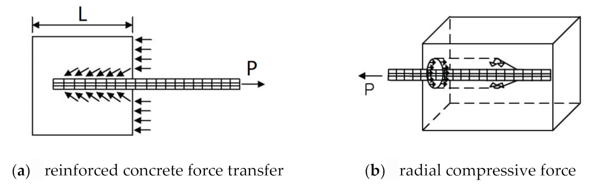
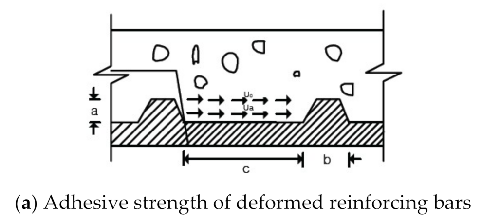
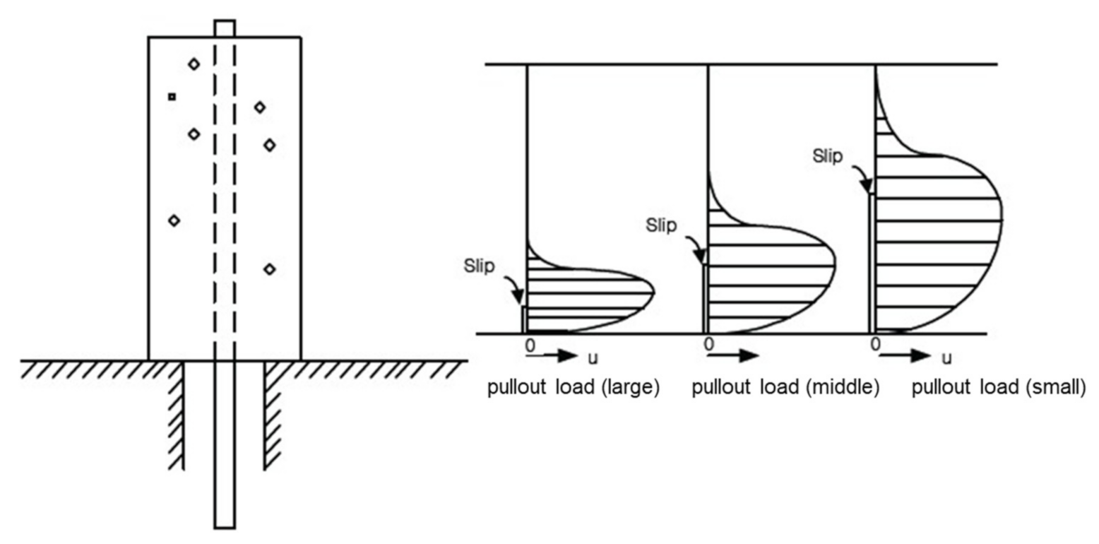
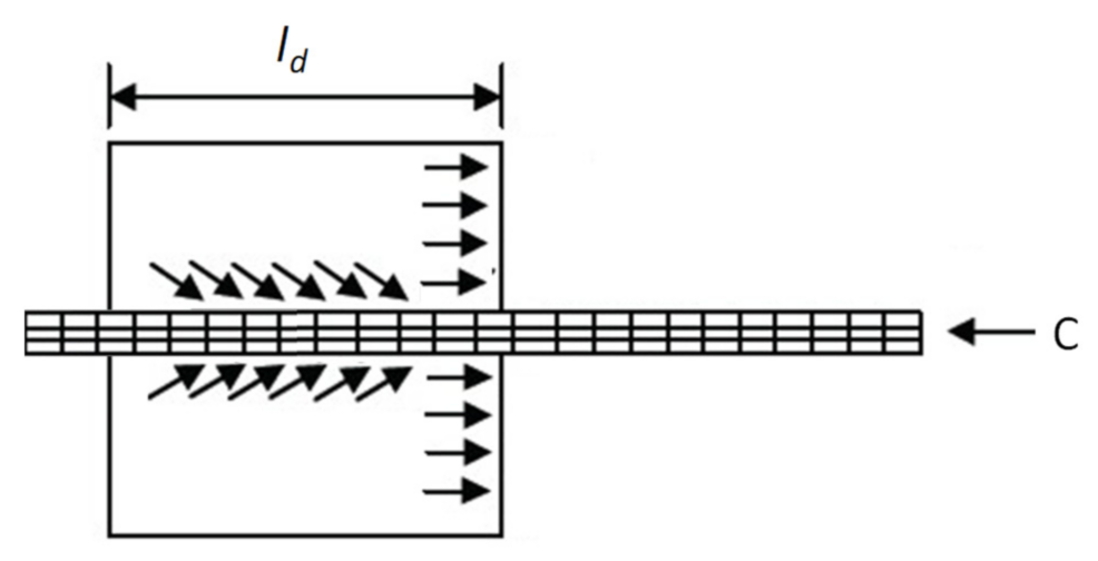
Adhesion mechanism of deformed reinforcing bars
The deformed reinforcing bars form ribs on the surface of the reinforcing bar, and the interaction between the ribs and the surrounding concrete causes a large adhesion. The adhesion stress generated between the ribs of the deformed reinforcing bars is related to the following stress, as shown in Figure 13.
Shear stress due to chemical adhesive force between the concrete and reinforced steel surface: va
Support stress due to dowel action on the rib surface of reinforcing steel: fb
Shear stress generated in the concrete between adjacent ribs: vc
Acts as the main element above ②.
Rehm et al. reported that the rib shape of the deformed reinforcing bar changes its adhesion at a/c and ap of 0.065. Therefore, a/c ≥ 1.5 is high, a/c ≥ 0 is broken, and the rib spacing is 10 times higher.
Figure 14 shows the dynamic structure of the forces generated by the reinforcing bars and concrete under load, which decompose into horizontal and vertical forces that act as the shear breaking forces of concrete between the ribs, and radial forces as tensile stress on the concrete around the reinforcing bars. Under load, chemical adhesion and friction between the reinforcing steel and concrete are initially lost, and adhesion is transferred when inclined pressure is applied to the reinforcing steel ribs, as shown in Figure 14a. Simultaneously, the opposite shiatsu stress of the same size is decomposed into longitudinal and vertical forces, as shown in Figure 14b,d. The vertical force creates tensile stress in the circumferential direction on the concrete around the reinforcement, causing the concrete to be destroyed.
(c)
Experimental methods and calculations
This test is based on the ASTM C 234 (pull-out test) and is a test method for deformed reinforcing bars. It is simple and reliable; therefore, it is useful for comparing the adhesion performance between different types of reinforcing steel and for checking the effect of concrete conditions. The average adhesion resistance u is calculated by assuming uniform adhesion on the length of the reinforcement insertion.

4.4. Prerequisite

(1) Considering the research conducted by Rehm et al., the fracture characteristics for the range a/c ≥ 0.15, and a/c ≤ 0.10 were not identified, but because they were close to the condition a/c ≤ 0.10, as shown in Table 6 and Figure 15, it is determined that the fracture occurs [57].
(2) For loads, the actual adhesion stress was not evenly distributed, but in this experiment, it was assumed that the adhesion stress by the buried reinforcing bar was distributed to a certain extent.
(3) Based on Rehm’s study on the breakage of deformed reinforcing bars, it was assumed that the adhesive force between the two materials is initially lost, and thus the tensile stress generated in the concrete was calculated and evaluated [57].

5. Calculations and Evaluation

The diameter of the reinforcing bars was taken as d. Calculations were performed to quantitatively evaluate the constraint stress of the concrete due to changes in the coating thickness. As shown in Figure 16, when a compression force C was applied to a reinforcing bar with a diameter of d, it was transferred to the concrete via the compression stress of the reinforcing bar with an adhesion length of l. Formula (14) is obtained when the unit average adhesion stress τb acts on the surface area πdl of the reinforcement.
C = π d l τ b
where C is the compressive force acting on the reinforcement, D the Rebar diameter, L is the length of specimen, and τb is the unit average adhesion stress.
(d)
Experimental results and considerations
When using D19 reinforcing steel as shown in Figure 17a, the reference specimen that was not induction-heated was compared with the specimen that was induction-heated on the entire surface according to the length direction of the reinforcing steel as shown Table 7. Further, when conducting induction heating, it was determined that the thermal expansion pressure generated in the reinforcing steel caused cracks in the ribs of the rebar with the largest surface area, thereby reducing the adhesion strength. Furthermore, when comparing non-heated reference specimens with only the center heated specimens, it is assumed that the total load is the same in the area below the reinforcement ribs of the entire specimen, and thus, the adhesion strength due to induction heating was evaluated.
Consequently, the test specimen heated only by the center showed 58, 8.3, and 11.5% reduction rates in the order of 30, 40, and 50 mm, respectively, while 58, 8.9, and 12 reduction rates were observed in the concrete stress. In the case of test specimens heated entirely by reinforcing steel, the reduction rates were 61, 29, and 11.5% in the order of 30, 40, and 50 mm, respectively, and 63, 27.8, and 12%, respectively. The 30 mm specimen with high heating efficiency showed a reduction of more than 60% in the adhesion strength, and the overall temperature of the reinforcing steel increased owing to the heat conduction of the reinforcing steel, and showed no significant difference compared to the total heating specimen. In addition, on reducing the heating efficiency, the difference between local heating and total heating is approximately 20% or greater, and further, if the heating efficiency is reduced by distance, the range of expansion pressure generation on reinforcing bars due to heat conduction is significantly reduced. Furthermore, when cracks from the reinforced ribs are connected to the surface of the concrete, the stress of the concrete is reduced by the same width in proportion to the stress reduction difference for which the ribs are responsible.
For the test specimen using D25 as shown in Figure 17c reinforcement, the adhesion strength reduction rates were 27.3, 23.2, and 17.4% in the order of 30, 40, and 50 mm, respectively. Although the rib stress and concrete constraint stress were proportionally reduced, the rib constraint stress reduction rate was observed to be slightly higher. For a test specimen using D32 as shown in Figure 16d, the reduction rates of 15.4, 17, and 17% are shown in the order of 30, 40, and 50 mm, respectively. Furthermore, the cross-sectional area of adhesion is large, and the reduction rate of the adhesion strength by induction heating is reduced as the heating efficiency is reduced. In addition, there was no significant difference observed in the reduction rates of the rib stress and concrete constraint stress.
When considering a test specimen using D10 as shown in Figure 17b reinforcing steel, the distribution of stress was found to be changed owing to the effect of the reinforcing bar buckling, and the reduction rate of adhesion strength was not significant. For local induction heating, it was determined that larger the diameter of the reinforcing bar, lower the thermal conductivity, proportional to the area, and greater the heat loss due to the heat transfer, for the proportional size and range of the reinforcing bar ribs. In addition, if cracks occur due to reinforcement expansion pressure, it was found that that most cracks occur in the reinforcement ribs, and as they progress to the concrete surface, the stress is reduced, which eventually results in the adhesion strength being reduced.
In this experiment shown in Figure 18, it was assumed that the effects of chemical friction were ignored in the beginning, but it was determined that the heat generated on the surface of the reinforcing steel ribs would affect the concrete vulnerability between the lower and rib nodes. Thus, further experiments and analyses of this is necessary in future research.

5.1. Evaluation of Rebar Recovery Rate after High-Frequency Induction Heating

The following steps consist of measuring the amount of concrete remaining on the reinforcing steel after high-frequency induction heating and evaluating the recovery rate of concrete by heating (reinforcement quality). For high-frequency induction heating, the concrete around the reinforcing steel was weakened by the rapid temperature increase of the surface of the reinforcing steel, and the difference can be quantitatively evaluated to provide basic data on the reutilization rate after demolition and separation.
(1)
Experimental Methods
A 30-mm thick reinforced concrete specimen was manufactured for each water binder ratio and heated for 360 s under high-frequency induction heating. Following the heating, the reinforcing bars and concrete lumps were separated using the hammering method, with the separated reinforcing bars being placed in a 100 mL beaker and the laboratory solution (10% hydrochloric acid solution) filled up to 100 mL. After 24 h, the reinforcing steel was collected, the remaining solution was dried at 100–110 °C, and the remaining powder was weighed. In addition, experiments were conducted using reinforcing bars of the same length, as described above, and the amount of powder dropped from the reinforcing bars in addition to the residual concrete by the laboratory solution was measured. Subsequently, the average amount of powder dropped from 10 reinforcing bars was calculated, and the result provided a measurement of only the concrete residue. The experimental factors and some photographs are presented in Table 8 and Figure 19.
(2)
Results and considerations
An experiment was conducted using a 30 mm-thick reinforced concrete specimen of D10 with the ratio of the water binder as a factor. Figure 20 shows the results of the rebar recovery experiment using induction heating. The higher the water-binder ratio, the higher was the recovery rate. The water binder ratio increased by approximately 17% and 7% in the case of 40% and 50%, respectively. For the same reinforcement diameter and heating distance, it was determined that higher the water–binder ratio, larger the range of evaporation of free water due to induction heating, and hence, greater the range of voids around the reinforcement.

5.2. Fragility of Cross Reinforced Concrete Using High Frequency Induction Heating Method

5.2.1. Experimental Factors and Levels

Herein, the reinforcement arrangement inside the reinforced concrete as shown in Table 9, Table 10, Table 11 is implemented in the same manner as in the actual structure. It was found that when heated using high-frequency induction heating, a vortex current was generated around the upper reinforcing bar, and when the coating thickness was small, the lower reinforcing bar entered the magnetic field and generated heat; however, most of the temperature increased owing to heat conduction. This section attempts to clarify the temperature rise characteristics by heat conduction and understand the crack characteristics by the shape and heating position of the iron bar after the reinforcement is heated.

5.2.2. Manufacturing and Testing Methods of Induction Heating Specimens

In this experiment, thermocouples were buried in concrete, which measured the temperature, and thereafter, the temperature rise characteristics of the reinforcing steel using the high-frequency induction heating method was evaluated in a dry concrete experiment. As shown in Figure 21, three D10 reinforcements were arranged in the upper part at a distance of 60 mm from the surface of the reinforcement to the adjacent reinforcement. Subsequently, the diameters of the upper and lower reinforcing bars were calculated, and the reinforced concrete experiment was performed according to the coating thickness. In the heating system, the maximum output was divided into 5 and 10 kW, and the heating coil was placed at the center of the laboratory and the center of the well-shaped reinforcing bar to measure the temperature. The temperatures of the upper and lower reinforcing bars with the heating coils in the center and the surface parts of 60 and 90 mm were measured, followed by the temperature measurements of the upper and lower reinforcing bars and the center parts of the intersection.

5.2.3. Experimental Results

(1)
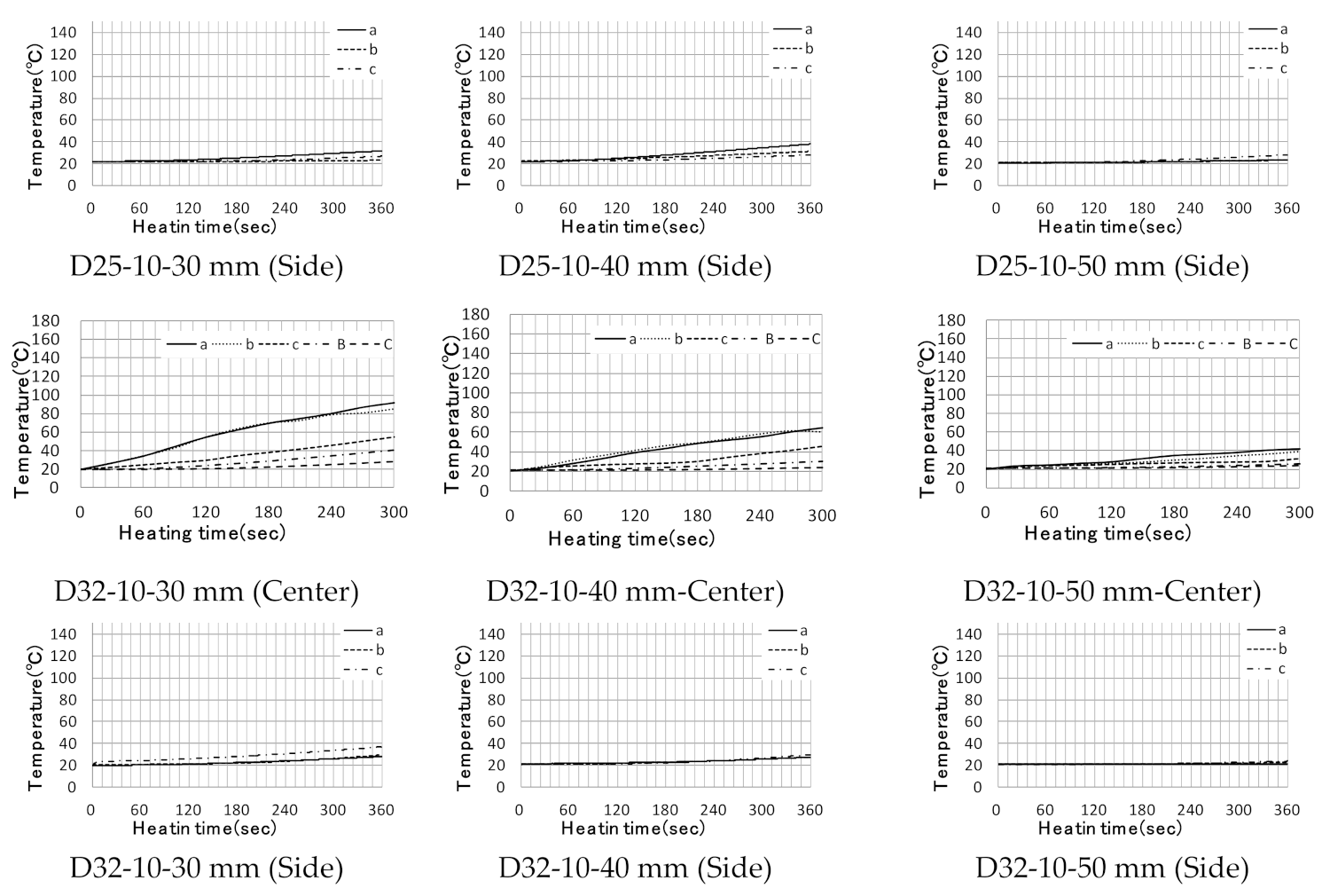
Temperature Rise Characteristics of Cross-Reinforced Concrete Subjected to High-Frequency Induction Heating
Figure 22 shows the trends of temperature during the reinforced concrete experiment. The reinforced concrete was realized with crossing reinforcing bars as actual members, arranging three D10 reinforcing bars in the upper part, and using D19, D25, and D32 reinforcing bars as the main reinforcing bars. The experiment was conducted by dividing the heating position into the center and side, and the results were analyzed with respect to the diameter, heating distance, and heating position of the used reinforcing bar. When the coil was located at the center, the lower reinforcement indicated no significant temperature difference, however, the upper D10 reinforcement indicated a temperature rise of up to 100 °C compared to the lower reinforcement and reinforcement on both sides. This trend has been observed in almost all laboratories, and the thicker the cover of concrete, the smaller the width of the temperature difference; however there was a clear difference in the trend here. In addition, it was found that the temperature rise shows a large difference in temperature compared to the experimental body that heated the center. This is probably because when the intersection is heated, a magnetic field is formed around the reinforcing steel closest to the heating coil, causing heat generation, and when the heat capacity of the reinforcing steel exceeds within the magnetic field range. If the heating coil is located at the center of the reinforcement, an eddy current is formed over the two faces of the upper and lower reinforcements, which may result in a performance degradation from a heating efficiency perspective. When applied to actual members, if the shape of the coil is in contact with the surface, it is considered that heating the intersection of the reinforcing steel will result in a higher heating efficiency.
(2)
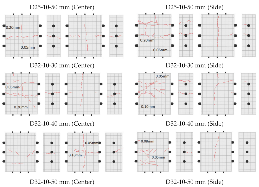
Crack Characteristics of Cross-Reinforced Concrete due to High-Frequency Induction Heating
For cross-reinforced concrete, D10 reinforcing bars were used as the upper reinforcing bars, while D19, D25, and D32 were used as lower reinforcing bars, and the center and side parts were induction-heated to evaluate the crack characteristics. Figure 23 shows the crack characteristics of the cross-reinforced concrete by high-frequency induction heating. During the center heating of the cross-reinforced concrete, cracks occurred in all specimens according to the upper and lower reinforcing bars, and the cracks continued to progress until the reinforcing bars were exposed. It was found that closer the heating distance, wider the crack, and farther the heating distance, the narrower the crack width. In addition, when the heating distance was close, cracks in the upper reinforced concrete surface progressed to the lower part, which was obvious as the diameter of the reinforced steel increased. In addition, in the case of 30 mm thick specimens using D19 and D25 reinforcing bars with high heating efficiency, cracks covering the exposed reinforcing bars were also identified, and they had a significant effect on the reduction of adhesion stress between the reinforcing bars and concrete.
As mentioned above, single reinforced concrete using D10 reinforcing bars exhibits a lower thermal expansion force owing to the reduced cross-sectional area compared to the heating efficiency. However, if upper reinforcing bars are used, cracks are observed along the D10 reinforcing bars, which progress toward the exposed reinforcing bars. This phenomenon is the result of penetrating cracks perpendicular to the reinforcement in the single reinforced concrete, while most stress was lost vertically in the case of cross-reinforced concrete owing to its large constraint range. Furthermore, cracks tend to occur along the upper reinforcing bar and thereafter along the lower reinforcing bar because cracks in the lower reinforcing bar occur due to heat conduction. As for side heating, well-shaped cracks occurred in the lower and upper reinforcing bars in the 30 mm specimen with a close heating distance. However, the farther the distance, the lower the temperature rise characteristic was compared to the center heating. Therefore, the more the crack increases, the lesser it is due to the increase in distance. Furthermore, when the heating distance was close, cracks occurred more frequently than in center heating. At the time of final separation, the heating range was wider than that of the center heating, but the separation performance was due to the deterioration of the temperature rise characteristics.
Moreover, the widths of cracks during and after heating are different from those of single reinforced concrete as show in Figure 24, but because it is difficult to measure the widths of cracks during heating, the measurement were done after heating. In terms of crack width, closer the heating distance is, larger the crack width, and there is no large difference according to the diameter of the reinforcing bar.

6. Conclusions

In this study, an experiment was conducted on a reinforced concrete specimen cross-arranged with a single buried reinforced concrete. The manufactured specimen was heated using a high-frequency induction heating system, and the temperature along with the temperature distribution of the surface of the reinforcing bar were examined based on the diameter, length, bar arrangement condition, heating distance, heating coil position, and output. Furthermore, the following conclusions were drawn after examining the dynamic and physical properties of the reinforced concrete specimen in terms of the expansion pressure and thermal conduction of the reinforced concrete owing to high-frequency induction heating.
(1)
For a single reinforced concrete, the temperature difference between concrete and non-range concrete within the induction heating range is large. This is the result of heating the reinforcing steel in the air using a high-frequency induction heating method.
(2)
When performing high-frequency induction heating of air-dry and absolute-dry single reinforced concrete, a more significant temperature increase was seen in dry conditions. This is more clearly exhibited by the reinforcing bars with D19 and D25, which have a higher heating efficiency.
(3)
The maximum output of a test specimen with a single reinforcement showed a sharp decrease in heating efficiency at a heating distance of 50 mm, while the maximum output at 10 kW showed excellent heating efficiency at a heating distance of 50 mm. However, when the heating distance was short, there was no significant difference in the temperature trend.
(4)
In single reinforced concrete specimens, cracks occurred in the direction perpendicular to the reinforcing bar in most specimens. However, over a short distance, cracks occurred in both directions. In addition, when the cross-sectional area of the reinforcing steel was reduced, the range of cracks increased owing to the increase in thermal conduction efficiency, but the width of cracks decreased owing to the decrease in the expansion pressure. In contrast, when full heating was carried out, the cracks were generated continuously even if the length and circumference of the reinforcement were followed. It was found that cracks had a significant effect on the reduction of the confinement stress of concrete.
(5)
In the case of high-frequency induction heating, there was no large difference in the air gap volume due to the water–binder ratio, but it was determined that dehydration of the gel and capillary water occurred, and calcium hydroxide was decomposed and evaporated, resulting in a significant increase in the air gap volume. This was confirmed both from the results of TGDTA and the measurement of changes in heat absorption intervals due to the decomposition of calcium hydroxide. Accordingly, when high-frequency induction heating was performed, it was determined that heat of approximately 500–600 °C is conducted on the concrete attached to the surface of the reinforcing steel.
(6)
Local induction heating was found to increase with the diameter of the reinforcing bar and decrease with the thermal conductivity. Moreover, it was proportional to the area of the bar. However, owing to the increased heat loss due to heat transfer, the size and range of the reinforcing bar ribs were proportionally reduced. In addition, if cracks occur owing to the expansion pressure of the reinforcing steel, they are mostly localized in the reinforcing steel ribs, and as they progress to the concrete surface, the stress is reduced eventually resulting in the reduction of the adhesion strength.
(7)
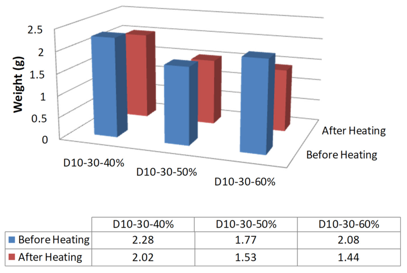
If the reinforcing bars have the same diameter and heating distance, the higher the water–binder ratio, the larger the range of evaporation of free water due to induction heating, and the greater the range of air gaps around the reinforcing bars.
(8)
Finally, for the crossed reinforcing bars, it was found that the heating range of the intersection was higher than that of heating between the reinforcing bars, where the heating range was smaller. Heating between reinforcing bars produced more cracks than heating at an intersection of the reinforcing bars, which is close to the heating distance, as determined by the fact that the heating range is wider on the final separation side, but the temperature rise characteristics are reduced.

Author Contributions

Conceptualization, M.-k.L.; methodology, M.-k.L.; investigation, M.-k.L.; data curation, M.-k.L.; writing—original draft preparation, C.L.; writing—review and editing, C.L. Both authors have read and agreed to the published version of the manuscript.

Funding

This work was funded by the Korea Meteorological Administration Research and Development Program under Grant KMI (2021-00811).

Institutional Review Board Statement

Not applicable.

Informed Consent Statement

Not applicable.

Data Availability Statement

Not applicable.

Conflicts of Interest

The authors declare no conflict of interest.

References

  1. Neville, A. Chloride attack of reinforced concrete: An overview. Mater. Struct. 1995, 28, 63–70. [Google Scholar] [CrossRef]
  2. Washer, G.A. Developments for the non-destructive evaluation of highway bridges in the USA. NDT E Int. 1998, 31, 245–249. [Google Scholar] [CrossRef]
  3. Jang, B.S.; Oh, B.H. Effects of non-uniform corrosion on the cracking and service life of reinforced concrete structures. Cem. Concr. Res. 2010, 40, 1441–1450. [Google Scholar] [CrossRef]
  4. Shah, A.A.; Ribakov, Y. Non-destructive measurements of crack assessment and defect detection in concrete structures. Mater. Des. 2008, 29, 61–69. [Google Scholar] [CrossRef]
  5. Poursaee, A.; Hansson, C.M. Potential pitfalls in assessing chloride-induced corrosion of steel in concrete. Cem. Concr. Res. 2009, 39, 391–400. [Google Scholar] [CrossRef]
  6. Legat, A.; Leban, M.; Bajt, Z. Corrosion processes of steel in concrete characterized by means of electrochemical noise. Electrochim. Acta 2004, 49, 2741–2751. [Google Scholar] [CrossRef]
  7. McCann, D.M.; Forde, M.C. Review of NDT methods in the assessment of concrete and masonry structures. NDT E Int. 2001, 34, 71–84. [Google Scholar] [CrossRef]
  8. Pradhan, B.; Bhattacharjee, B. Performance evaluation of rebar in chloride contaminated concrete by corrosion rate. Constr. Build. Mater. 2009, 23, 2346–2356. [Google Scholar] [CrossRef]
  9. Parthiban, T.; Ravi, R.; Parthiban, G.T. Potential monitoring system for corrosion of steel in concrete. Adv. Eng. Softw. 2006, 37, 375–381. [Google Scholar] [CrossRef]
  10. Pour-Ghaz, M.; Isgor, O.B.; Ghods, P. Quantitative interpretation of half-cell potential measurements in concrete 8 Advances in Civil Engineering structures. J. Mater. Civ. Eng. 2014, 21, 467–475. [Google Scholar] [CrossRef]
  11. Hornbostel, K.; Larsen, K.; Geiker, M.R. Relationship between concrete resistivity and corrosion rate—A literature review. Cem. Concr. Comp. 2013, 39, 60–72. [Google Scholar] [CrossRef]
  12. Takahashi, Y.; Matsubara, E.; Suzuki, S.; Okamoto, Y.; Komatsu, T.; Konishi, H.; Mizuki, J.; Waseda, Y. In-situ x-ray diffraction of corrosion products formed on iron surfaces. Mater Trans. 2005, 46, 637–662. [Google Scholar] [CrossRef] [Green Version]
  13. Yeih, W.; Huang, R. Detection of the corrosion damage in reinforced concrete members by ultrasonic testing. Cem. Concr. Res. 1998, 28, 1071–1083. [Google Scholar] [CrossRef]
  14. Ahmed, R.; Rifat, A.A.; Yetisen, A.K.; Salem, M.S.; Yun, S.-H.; Butt, H. Optical microring resonator based corrosion sensing. RSC Adv. 2016, 6, 56127–56133. [Google Scholar] [CrossRef]
  15. Vrana, J.; Goldammer, M.; Bailey, K. Induction and conduction thermography: Optimizing the electromagnetic excitation towards application. Rev. Prog. Quant. Nondestruct. Eval. 2009, 28, 518–525. [Google Scholar]
  16. Zhang, H.; Liao, L.; Zhao, R.; Zhou, J.; Yang, M.; Zhao, Y. A new judging criterion for corrosion testing of reinforced concrete based on self-magnetic flux leakage. Int. J. Appl. Electromagn. Mech. 2017, 54, 123–130. [Google Scholar] [CrossRef]
  17. Gonzalez, J.A.; Cobo, A.; Gonzalez, M.N.; Feliu, S. Onsite determination of corrosion rate in reinforced concrete structures by use of galvanostatic pulses. Corros. Sci. 2001, 43, 611–625. [Google Scholar] [CrossRef]
  18. Abidin, I.Z.; Gui, Y.T.; Wilson, J. Quantitative evaluation of angular defects by pulsed eddy current thermography. NDT E Int. 2010, 43, 537–546. [Google Scholar] [CrossRef]
  19. Clark, M.R.; McCann, M.R.; Forde, M.C. Application of infrared thermography to the non-destructive testing of concrete and masonry bridges. NDT E Int. 2003, 36, 265–275. [Google Scholar] [CrossRef]
  20. Clark, M.; McCann, D.M.; Forde, M.C. Infrared thermographic investigation of railway track ballast. NDT E Int. 2002, 35, 83–94. [Google Scholar] [CrossRef]
  21. Defer, D.; Shen, J.; Lassue, S.; Duthoit, B. Non-destructive testing of a building wall by studying natural thermal signals. Energy Build. 2002, 34, 63–69. [Google Scholar] [CrossRef]
  22. Engelbert, P.J.; Hotchkiss, R.H.; Kelly, W.E. Integrated remote sensing and geophysical techniques for locating canal seepage in Nebraska. J. Appl. Geophys. 1997, 38, 143–154. [Google Scholar] [CrossRef]
  23. Sakagami, T.; Kubo, S. Applications of pulse heating thermography and lock-in thermography to quantitative nondestructive evaluations. Infrared Phys. Technol. 2002, 43, 211–218. [Google Scholar] [CrossRef]
  24. Baek, S.; Xue, W.; Feng, M.Q.; Kwon, S. Non-destructive corrosion detection in RC through integrated heat induction and IR thermography. J. Nondestruct. Eval. 2012, 31, 181–190. [Google Scholar] [CrossRef]
  25. Weekes, B.; Almond, D.P.; Cawley, P.; Barden, T. Eddy current induced thermography-probability of detection study of small fatigue cracks in steel, titanium and nickel-based superalloy. NDT E Int. 2012, 49, 47–56. [Google Scholar] [CrossRef]
  26. He, Y.; Pan, M.; Tian, G.; Chen, D.; Tang, Y.; Zhang, H. Eddy current pulsed phase thermography for subsurface defect quantitatively evaluation. Appl. Phys. Lett. 2013, 103, 144108. [Google Scholar] [CrossRef]
  27. Liu, L.; Zheng, D.; Zhou, J.T.; He, J.; Xin, J.; Cao, Y. Corrosion detection of bridge reinforced concrete with induction heating and infrared thermography. Int. J. Robot. Autom. 2018, 33, 379–385. [Google Scholar] [CrossRef]
  28. Landau, L.D.; Lifshitz, E.M.; Pitaevskii, L.P. Electrodynamics of Continuous Media; Pergamon Press: Oxford, UK, 1960. [Google Scholar]
  29. Aguiar, P.M.; Jacquinot, J.F.; Sakellariou, D. Experimental and numerical examination of eddy (Foucault) currents in rotating micro-coils: Generation of heat and its impact on sample temperature. J. Magn. Reson. 2009, 200, 6–14. [Google Scholar] [CrossRef] [PubMed]
  30. Cheng, J.; Roy, R.; Agrawal, D. Radically different effects on materials by separated microwave electric and magnetic fields. Mater. Res. Innov. 2002, 5, 170–177. [Google Scholar] [CrossRef]
  31. Cherradi, A.; Desgardin, G.; Provost, J.; Raveau, B. Electric & Magnetic Field Contributions to the Microwave Sintering of Ceramics Elelctroceramics IV; Wasner, R., Hoffman, S., Bonnenberg, D., Hoffmann, C., Eds.; RWTN: Aachen, Germany, 1994; Volume 2, pp. 1219–1224. [Google Scholar]
  32. Cao, Z.; Wang, Z.; Yoshikawa, N.; Taniguchi, S. Microwave heating origination and rapid crystallization of PZT thin films in separated H field. J. Phys. D Appl. Phys. 2008, 41, 092003. [Google Scholar] [CrossRef]
  33. Jin, R.; Chen, Q. Investigation of concrete recycling in the U.S. construction industry. Procedia Eng. 2015, 118, 894–901. [Google Scholar] [CrossRef]
  34. Chen, C.; Habert, G.; Bouzidi, Y.; Jullien, A. Environmental impact of cement production: Detail of the different processes and cement plant variability evaluation. J. Clean. Prod. 2010, 18, 478–485. [Google Scholar] [CrossRef]
  35. Rodríguez, G.; Sáez del Bosque, I.F.; Asensio, E.; Sánchez de Rojas, M.I.; Medina, C. Construction and demolition waste applications and maximum daily output in Spanish recycling plants. Waste Manag. Res. 2020, 38, 423–432. [Google Scholar] [CrossRef]
  36. Li, Y.F. Dielectric Properties and Thermal Properties of Materials during Microwave Heating; Kunming University of Science and Technology: Kunming, China, 2012. [Google Scholar]
  37. Peng, Z.; Hwang, J.Y.; Park, C.L.; Kim, B.-G.; Onyedika, G. Numerical analysis of heat transfer characteristics in microwave heating of magnetic dielectrics. Metall. Mater. Trans. A 2012, 43, 1070–1078. [Google Scholar] [CrossRef]
  38. Zhu, J.; Kuznetsov, A.V.; Sandeep, K.P. Mathematical modeling of continuous flow microwave heating of liquids (effects of dielectric properties and design parameters). Int. J. Therm. Sci. 2007, 46, 328–341. [Google Scholar] [CrossRef]
  39. Catalá-Civera, J.M.; Canós, A.J.; Plaza-González, P.; Gutierrez, J.D.; Garcia-Banos, B.; Penaranda-Foix, F.L. Dynamic measurement of dielectric properties of materials at high temperature during microwave heating in a dual mode cylindrical cavity. IEEE Trans. Microw. Theory Tech. 2015, 63, 2905–2914. [Google Scholar] [CrossRef]
  40. Szychta, E.; Szychta, L. Comparative analysis of effectiveness of resistance and induction turnout heating. Energies 2020, 13, 5262. [Google Scholar] [CrossRef]
  41. BSI. Eurocode 2: Design of Concrete Structures-Part 1–2: General Rules-Structural Fire Design; BSI: London, UK, 2004; pp. 26–29. [Google Scholar]
  42. ASTM C234. Standard Test Method for Comparing Concrete on the Basis of the Bond Developed with Reinforced Steel; ASTM: West Conshohocken, PA, USA, 1991. [Google Scholar]
  43. Lie, T.T. Fire and Buildings; Applied Science Publishers Ltd.: London, UK, 1972; p. 276. [Google Scholar]
  44. Lie, T.T. Structural Fire Protection; ASCE Manuals and Reports on Engineering Practice, No. 78; ASCE: New York, NY, USA, 1992; p. 241. [Google Scholar]
  45. Lie, T.T.; Lin, T.D.; Allen, D.E.; Abrams, M.S. Fire Resistance of Reinforced Concrete Columns; Technical Paper, No. 378; Division of Building Research, National Research Council of Canada: Ottawa, ON, Canada, 1984.
  46. El-Fitiany, S.F.; Youssef, M.A. Assessing the flexural and axial behaviour of reinforced concrete members at elevated temperatures using sectional analysis. Fire Saf. J. 2009, 44, 691–703. [Google Scholar] [CrossRef]
  47. Kodur, V.K.R.; Sultan, M.A. Effect of temperature on thermal properties of high-strength concrete. ASCE J. Mater. Civ. Eng. 2003, 15, 101–107. [Google Scholar] [CrossRef]
  48. Harmathy, T.Z. Fire Safety Design and Concrete; Longman Scientific & Technical: Harlow, UK, 1993. [Google Scholar]
  49. Schneider, U. Properties of Materials at High Temperatures-Concrete, 2nd ed.; RILEM Report; Gesamthochschule: Kassel, Germany, 1986. [Google Scholar]
  50. Lim, M.; Choi, H.; Choi, H.; Kitagaki, R.; Noguchi, T. Development of Eco-Friendly Deconstruction Technologies for Recycling Construction Waste. J. Environ. Prot. 2014, 5, 647–661. [Google Scholar] [CrossRef] [Green Version]
  51. Schneider, U. Behavior of Concrete at High Temperatures; Wilhelm Ernst & Sohn: Berlin, Germany, 1982. [Google Scholar]
  52. Bažant, Z.P.; Kaplan, M.F.; Bazant, Z.P. Concrete at High Temperatures: Material Properties and Mathematical Models; Prentice Hall: Hoboken, NY, USA, 1996. [Google Scholar]
  53. Arioz, O. Effect of elevated temperatures on properties of concrete. Fire Saf. J. 2007, 42, 516–522. [Google Scholar] [CrossRef]
  54. Ichikawa, Y. Prediction of Pore Pressures, Heat and Moisture Transfer Leading to Spalling of Concrete during Fire. Ph.D. Thesis, Imperial College, University of London, London, UK, 2000. [Google Scholar]
  55. Vedalakshmi, R.; Raj, A.S.; Srinivasan, S.; Babu, K.G. Quantification of hydrated cement products of blended cements in kow and medium strength concrete using TG and DTA technique. Thermochim. Acta 2003, 407, 49–60. [Google Scholar] [CrossRef]
  56. Choi, E.; Kim, Y.W.; Chung, Y.S.; Yang, K.T. Bond strength of concrete confined by SMA wire jackets. Phys. Procedia 2010, 10, 210–215. [Google Scholar] [CrossRef] [Green Version]
  57. Rehm, G. Undet Die Grundlagen des Verbundes Zwischen Staglund Beton; Heft 138; Deutscher Ausschuss fur Staglbeton: Berlin, Germany, 1961; p. 59. [Google Scholar]
Figure 1. Thermal conductivity rate by rebar type [47].
Applsci 11 05402 g001
Figure 2. Model of reinforced concrete member vulnerability by induction heating.
Applsci 11 05402 g002
Figure 3. Test specimen production and control method.
Applsci 11 05402 g003
Figure 4. Stress–strain curve for normal concrete.
Applsci 11 05402 g004
Figure 5. Increase in temperature with time in reinforced concrete during induction heating.
Applsci 11 05402 g005aApplsci 11 05402 g005b
Figure 6. Increase in temperature with time in reinforced concrete caused by induction heating.
Applsci 11 05402 g006aApplsci 11 05402 g006b
Figure 7. Crack characteristics of single reinforced concrete by induction heating.
Applsci 11 05402 g007aApplsci 11 05402 g007b
Figure 8. Crack characteristics of single reinforced concrete by induction heating (full heating).
Applsci 11 05402 g008
Figure 9. Cracks in single reinforced concrete due to induction heating.
Applsci 11 05402 g009
Figure 10. Variation of single reinforced concrete gap structure due to induction heating in accordance with void diameter and amount voids.
Applsci 11 05402 g010
Figure 11. Thermal weight/differential thermal simultaneous analysis (TG-DTA) results.
Applsci 11 05402 g011
Figure 12. Rebar force transition structure [56].
Applsci 11 05402 g012
Figure 13. Adhesive fracture depending on the rib geometry of the deformed reinforcing bars [57].
Applsci 11 05402 g013aApplsci 11 05402 g013b
Figure 14. Reinforcement and concrete attachment structure.
Applsci 11 05402 g014
Figure 15. Adhesive tensile test and distribution of adhesive stress [57].
Applsci 11 05402 g015
Figure 16. Rebar force transition structure [57].
Applsci 11 05402 g016
Figure 17. Reinforced concrete extraction experiment results (D00-000: D reinforcement type-distance mm-heating-all heating).
Applsci 11 05402 g017
Figure 18. Rebar extraction experiment after induction heating.
Applsci 11 05402 g018
Figure 19. Workflow of the rebar recovery experiment.
Applsci 11 05402 g019
Figure 20. Results of rebar recovery experiment by induction heating.
Applsci 11 05402 g020
Figure 21. Test specimen production and control method.
Applsci 11 05402 g021
Figure 22. Temperature rising characteristics of reinforced concrete during induction heating.
Applsci 11 05402 g022aApplsci 11 05402 g022b
Figure 23. Crack characteristics of cross reinforced concrete by induction heating.
Applsci 11 05402 g023aApplsci 11 05402 g023b
Figure 24. Cracks in cross-reinforced concrete due to induction heating.
Applsci 11 05402 g024
Table 1. Experimental factors and levels.
TypePower (KW)Length of Reinforcement (mm)W/C (%)Heating Distance
(mm)
D1051017043040506020304050
D19
D25
D32
Table 2. Materials used.
SpecificationsPhysical Properties
cementPortland cementDensity: 3.16 [g/cm3], specific surface area: 3330 [cm2/g]
fine aggregateAquatic Land Sand (S)Front dry density: 2.60 [g/cm3], FM: 2.55
coarse aggregateOme Crushed Stone 20~5 mmFront dry density: 2.66 [g/cm3], FM: 5
chemical blending materialAE water reducing agentPolycarboxylic acid series
Table 3. Concrete preparation.
Slump
(cm)
Air
(%)
W/C
(%)
Gmax
(mm)
S/a
(%)
W
(Kg/m3)
Weight Preparation (Kg/m3)Admixture
CSG
13.42402542180450707.2999.1C (0.3%)
13.11.9502545180360799.11003.44
13.41.6602547180300849.36979.92
Table 4. Reinforcing bar thermal expansion coefficient.
Temperature (°C)Expansion Rate (dL/L) (%)Coefficient of Expansion
(a) × 10−5
100.00.06111.0181
200.00.18171.1358
300.00.32231.2398
400.00.17461.3185
500.00.64071.3929
600.00.80441.4365
700.00.98251.4888
800.01.06701.4039
Table 5. Decomposed substances by temperature zone.
Temperature IntervalDecomposing Substance
110Physically contained water Etringite (3CaO·Al2O3·3CaSO4·32H2O)
110–300Calcium silicate (3CaO/2SiO2,3H2O)
290–350Calcium aluminate silicate, calcium aluminate (Ca2Al(OH)7.3H2O, or 4CaO·Al2O3·13H2O), calcium chloroaluminate (3CaO·Al2O3·CaCl2·10H2O)
400–510Calcium hydroxide (Ca(OH)2)
700–750Calcium carbonate (CaCO3)
Table 6. Calculation of fracture aspects of deformed reinforcing bars by ribs.
Typea/cCalculated Value
D100.6/6.70.0896
D191.5/13.40.112
D251.95/17.80.1096
D322.4/22.30.1076
Table 7. Calculation details of rebar adhesion strength.
TypeCrushing Load
(kN)
Total Area of Reinforcement Attachment
(mm2)
Crushing Strength
(MPa)
D10-30 mm-normal41.1611,743.603.5
D10-40 mm-normal49.0011,743.604.17
D10-50 mm-normal-11,743.60-
D10-30 mm-heating26.0111,743.602.20
D10-40 mm-heating37.0311,743.603.18
D10-50 mm-heating57.1111,743.604.88
D19-30 mm-normal130.0423,989.605.42
D19-40 mm-normal145.7123,989.606.07
D19-50 mm-normal156.8423,989.606.54
D19-30 mm-heating54.2223,989.602.26
D19-40 mm-heating132.6223,989.605.53
D19-50 mm-heating137.7923,989.605.79
D19-30 mm-heating
(All heating)
47.0423,989.601.96
D19-40 mm-heating
(All heating)
105.1823,989.604.38
D19-50 mm-heating
(All heating)
137.8023,989.605.72
D25-30 mm-normal180.1231,902.405.60
D25-40 mm-normal220.2231,902.406.94
D25-50 mm-normal230.1331,902.407.49
D25-30 mm-heating130.0831,902.404.07
D25-40 mm-heating168.9331,902.405.33
D25-50 mm-heating198.6131,902.406.19
D32-30 mm-normal247.7139,940.806.25
D32-40 mm-normal290.1339,940.807.28
D32-50 mm-normal333.8439,940.808.36
D32-30 mm-heating212.8339,940.805.29
D32-40 mm-heating243.1439,940.806.04
D32-50 mm-heating273.2539,940.806.88
Table 8. Experimental Factors.
TypeDistanceLength of ReinforcementW/CPowerHeating Position
D10-40%30 mm130 mm40%5 KWTotal heating
D10-50%50%
D10-60%60%
Table 9. Experimental factors and levels.
TypeDistanceLength of ReinforcementW/CPowerHeating Location
D19-1030 mm355 mm50%5 kW
10 kW
Center
Side
D25-1040 mm
D32-1050 mm
Table 10. Materials.
Name and TypePhysical Properties
CementPortland cementDensity: 3.16 [g/cm3], Specific surface area: 3330 [cm2/g]
Fine aggregateOigawa Water System Land Sand (S)Surface dry density: 2.60 [g/cm3], FM: 2.55
Coarse aggregateOme Crushed Stones 20–5 mmSurface dry density: 2.66 [g/cm3]
Chemical admixtureAE water reducing agentpolycarboxylic acid series
Table 11. Concrete preparation.
Slump
(cm)
Air
(%)
W/C
(%)
Gmax
(mm)
S/a
(%)
Wunit
(Kg/m3)
Weight Preparation (Kg/m3)Admixture
CSG
13.11.9502545180360799.11003.44C (0.3%)
Publisher’s Note: MDPI stays neutral with regard to jurisdictional claims in published maps and institutional affiliations.

