Article

Thermal Performance Assessment of a Wall Made of Lightweight Concrete Blocks with Recycled Brick and Ground Polystyrene

Faculty of Civil Engineering and Architecture Osijek, Josip Juraj Strossmayer University of Osijek, 3, Vladimir Prelog Street, 31000 Osijek, Croatia
*
Author to whom correspondence should be addressed.
Buildings 2021, 11(12), 584; https://doi.org/10.3390/buildings11120584
Submission received: 5 November 2021 / Revised: 19 November 2021 / Accepted: 23 November 2021 / Published: 25 November 2021
(This article belongs to the Collection Utilization of Waste Materials in Building Engineering)

Abstract

:
Hollow concrete masonry blocks made of low strength self-compacting concrete with recycled crushed brick and ground polystyrene as an aggregate (RBC-EP blocks), and their expected structural role as masonry infill in steel frames, has been confirmed in previous research studies, thus the extensive investigation of thermal properties is presented in this paper to fully approve their potential application in practice. The Heat Flow and Temperature Based Method was used to conduct in-situ measurements of the wall thermal transmittance (U-value). The experimental U-values of the wall without insulation varied from 1.363 to 1.782 W/m2·K, and the theoretical value was calculated to be 2.01 W/m2·K. Thermal conductivity of the material used for making RBC-EP blocks was measured in a laboratory by using a heat flow meter instrument. To better understand the thermal performance characteristics of a wall constructed from RBC-EP blocks, a comparison with standard materials currently used and found on the market was performed. Walls constructed from RBC-EP blocks show an improvement of building technology and environmentally based enhancement of concrete blocks, since they use recycled materials. They can replace standard lightweight concrete blocks due to their desired mechanical properties, as well as the better thermal performance properties compared to commonly used materials for building walls.

1. Introduction

The main issues of building stock within the European Union (EU) are vast energy consumption and greenhouse gas emissions [1], since the EU building sector is responsible for approximately 40% of energy consumption and 36% of CO2 emissions [1,2]. Existing buildings were constructed mostly in the 1970s, whereby 35% of the existing buildings are over 50 years old, and 75% of building stock is energy inefficient [3]. The issue becomes even greater, since 75–90% of existing buildings will stand in 2050 [3]. Actions undertaken during the building operational stage can be either refurbishment or retrofit, where refurbishment implies the necessary modifications to return a building to its original state, while retrofit includes the necessary actions that will improve the building’s energy and/or environmental performance [1]. The Energy Performance of Buildings Directive 2018/844/EU establishes a framework aiming at long term renovation of the existing building stock and decarbonization by 2050 [2]. Renovation of existing buildings does not necessarily decrease energy consumption. It also improves the whole condition of the building: its exploitation, noise insulation conditions, exterior, and comfort, all of which prolong a building’s life cycle, increases the value of the buildings, reduces negative impact to the environment, and guarantees healthy living and working conditions [2]. The main results expected from buildings refurbishment are [2]:
  • Energy savings;
  • Increase in comfort;
  • Healthy working environment assurance;
  • Extension of building life cycle;
  • Economized exploitation;
  • Environmental protection.
However, the renovation of buildings can also be an opportunity to contribute to sustainability by using new innovative building materials made from recycled materials. Partial or complete replacement of natural aggregate with secondary materials not only reduces the carbon footprint, but also reduces strain on already overflowing waste disposal sites. Previous research has also demonstrated that incorporating waste material of low thermal conductivity also improves thermal performance [3] of innovative building materials made from waste materials. By using the agricultural and industrial by-products or wastes, significant contributions can be made towards sustainable construction [4]. With that in mind, clay brick waste is especially interesting, as it is abundant as a demolition and manufacturing by-product (waste) material, which makes it environmentally and financially effective. There are also clear advantages from a structural point of view. Notably, the desired effects of strength and stiffness reduction in some applications can be achieved by replacing natural aggregate with a recycled crushed brick (RB) material in larger percentages. Taking into account all discussed aspects of desirable block for infill panels, blocks made of self-compacting concrete (SCC) with crushed brick and ground polystyrene as a replacement for natural aggregate were developed at the Faculty of Civil Engineering and Architecture in Osijek [5,6,7].
Notably, it is a well-known fact that masonry infill in steel or concrete frames affect their structural behavior. The interaction of masonry infill with the surrounding frame is significant under horizontal loads (especially earthquake action), in which case infill’s influence can be beneficial or detrimental. Positive effects, such as increased stiffness and strength, can be treated as redundant, and, consequently, neglected in general design; negative effects should not be ignored in active seismic areas. Higher seismic demand due to increased stiffness, potentially limited ductility due to earlier onset of plastic deformations, short column effect, and higher loads on connections due to masonry diagonal action are the main reasons why the infill’s influence is substantial and should be investigated in detail. The structural behavior of masonry infilled frames is very complex, and has been a subject of research for a few decades now, yet there are still no detailed codified rules for the design of masonry infilled frames. The typical approach to reinforced concrete frames is to integrate the contribution of masonry infill into the overall response of the structure, which offer various methods of additional infill strengthening. The opposite approach is typical for steel frames, which is to investigate and establish configuration of isolation of the masonry panel from the surrounding steel frame [8]. Most attempts to comply such a goal are referred either with some configuration of isolation of the masonry panel from the frame, or with the implementation of structural measures (devices) to modify the “natural” behavior of an infill panel.
The approach presented in [5,6] aims to exclude or at least limit detrimental effects of masonry infill to steel frames, but also utilize beneficial effects. Notably, instead of unavoidable adjustment to properties of commonly in use masonry blocks (mostly intended to be used as structural masonry), blocks that have an appropriate functional and structural role in the overall system should be available to the designers. In fact, it is important to note that masonry blocks used as infill do not need to be a part of the main structural system, as they do in masonry structures. Therefore, the solution could be in a new type of masonry blocks, i.e., masonry infill with a minimal detrimental impact on the surrounding frame, while retaining the useful masonry features mentioned earlier.
Clay masonry blocks have high strength combined with high stiffness, which is undesirable for filling. Unlike clay blocks, concrete provides different levels of strength, and consequently stiffness, and recycled materials can be used in its production as a secondary crushed material. These possibilities make concrete a sustainable choice in achieving both set structural and environmental goals.
It is often found that values of walls’ thermal transmittance (W/m2K) determined on-site in real conditions unquestionably deviate from the values theoretically obtained. This causes discrepancy between the actual thermal performance of a building envelope and the designed building envelope performance. This issue is particularly interesting when it comes to building external walls with new innovative materials where besides laboratory determined properties, building technology used plays a significant role. In this paper, thermal performance measurements of real size wall made from new masonry RBC-EP blocks were executed. Blocks are made of self-compacting concrete (SCC) with recycled crushed brick and ground polystyrene as a replacement for the aggregate [5].
The following techniques were used in this paper to determine the thermal properties of wall:
  • Infrared thermography (IRT) method to determine appearance of possible thermal bridges in the wall;
  • Heat Flow Method was used to estimate the thermal transmittance (U-Value) of the wall;
  • Temperature Based Method, a relatively new and simple non-standardized method, was also used to measure the U-value of the observed wall.
The thermal conductivity of the material (W/m·K) i.e., masonry blocks used for building real-sized walls, was measured in the laboratory by using a heat flow meter instrument. Since the wall was built inside laboratory as a part of test chamber, it was possible to carry out an airtightness examination of the test chamber, since measured values of airtightness (h−1) play an important role when concerning energy efficiency in buildings.
New masonry blocks with recycled clay brick can be used when buildings are refurbished due to their excellent thermal properties presented and confirmed in this paper—thermal resistance of blocks and thermal transmittance (U-Value) of walls (non-isolated and isolated)—especially when keeping in mind other excellent properties of these blocks already presented in [5,6,7,9].

2. Experimental Investigation

2.1. Previous Experimental Testing

The first step in the design of a new masonry block was to develop an appropriate SCC composition of mixture. Natural aggregate was fully replaced with recycled clay bricks (RB), obtained as an industrial waste product, and with a combination of RB and ground expanded polystyrene (GEP), obtained by mechanical recycling of expanded polystyrene (EP). In total, thirteen SCC mixtures were designed and tested in accordance with EN 12,390 [10,11,12] and EN 12390-2 [13]. Concrete compositions and the results of mechanical and physical properties were measured and shown in [5], and the following conclusions were made:
  • densities of all mixtures were lower than 2000 kg/m3, thus they were classified as lightweight concretes;
  • results of testing confirm that designed mixtures of SCC are of low-strength and stiffness, which was in line with the set objectives.
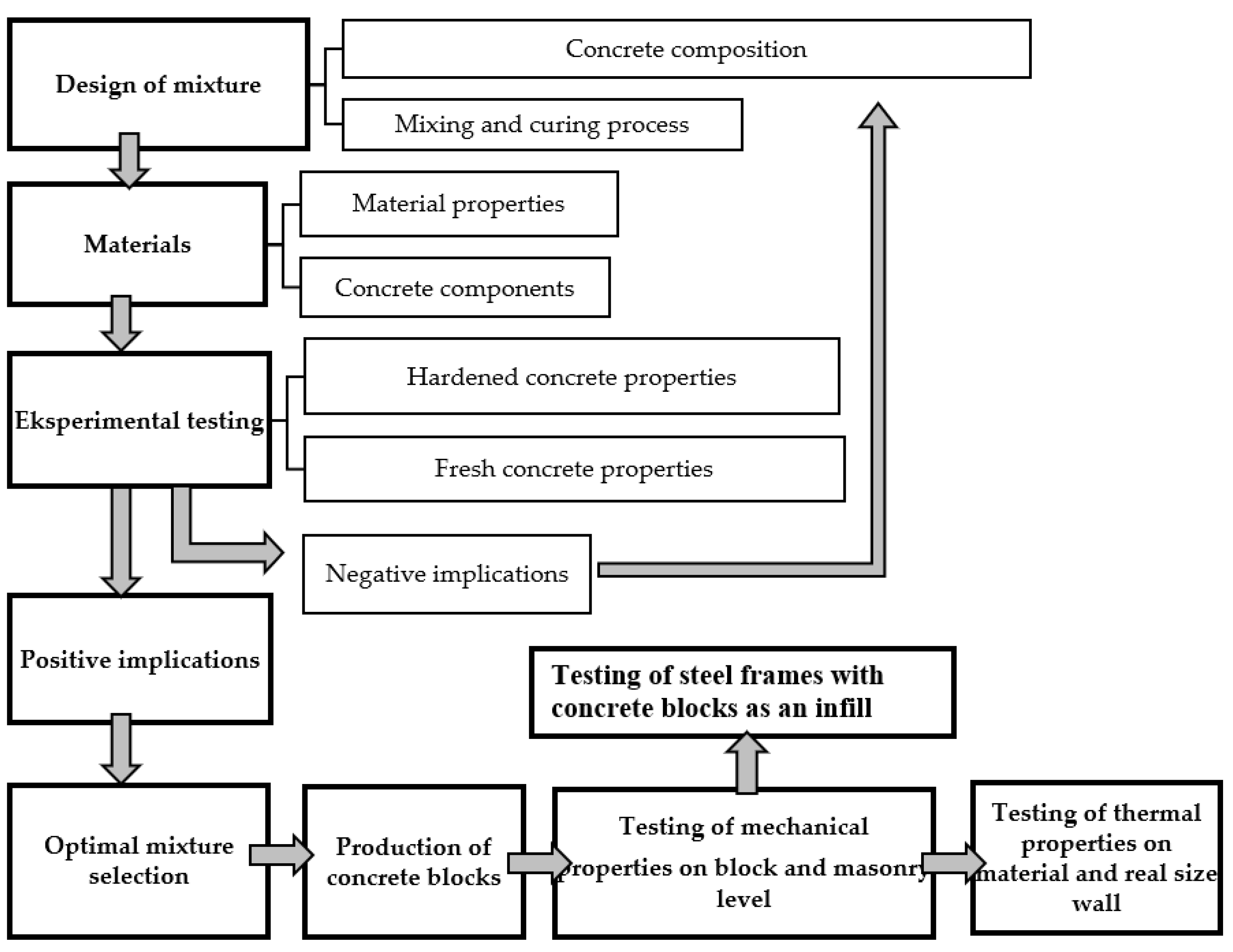
The next step was to design an appropriate block for further investigations, considering EN 1996-1-1 guidelines (Figure 1). Since the thermal conductivity of concrete is much higher than that of air, it was significantly reduced by creating more cavities or air gaps in the concrete blocks [14]. Molds for concrete blocks were manufactured in compliance with EN 772-2 [15] and EN 772-16 [16]. Based on measured properties in fresh (EN 12,350 [17,18,19,20]—density, viscosity class, passing ability) and hardened states (EN 12,390 [10,11,12]—compressive strength, flexural strength, density, and modulus of elasticity) and their positive and negative implications—the optimal mixture was selected for production of concrete blocks, and for testing mechanical properties on block and masonry level. Blocks made with a combination of recycled crushed brick aggregate and ground expanded polystyrene (RBC-EP) were selected for usage in frames. Results of the previous research [5,6] regarding the mixture RBC-EP are shown in Table 1. The flowchart of the experimental investigation is presented in Figure 2.
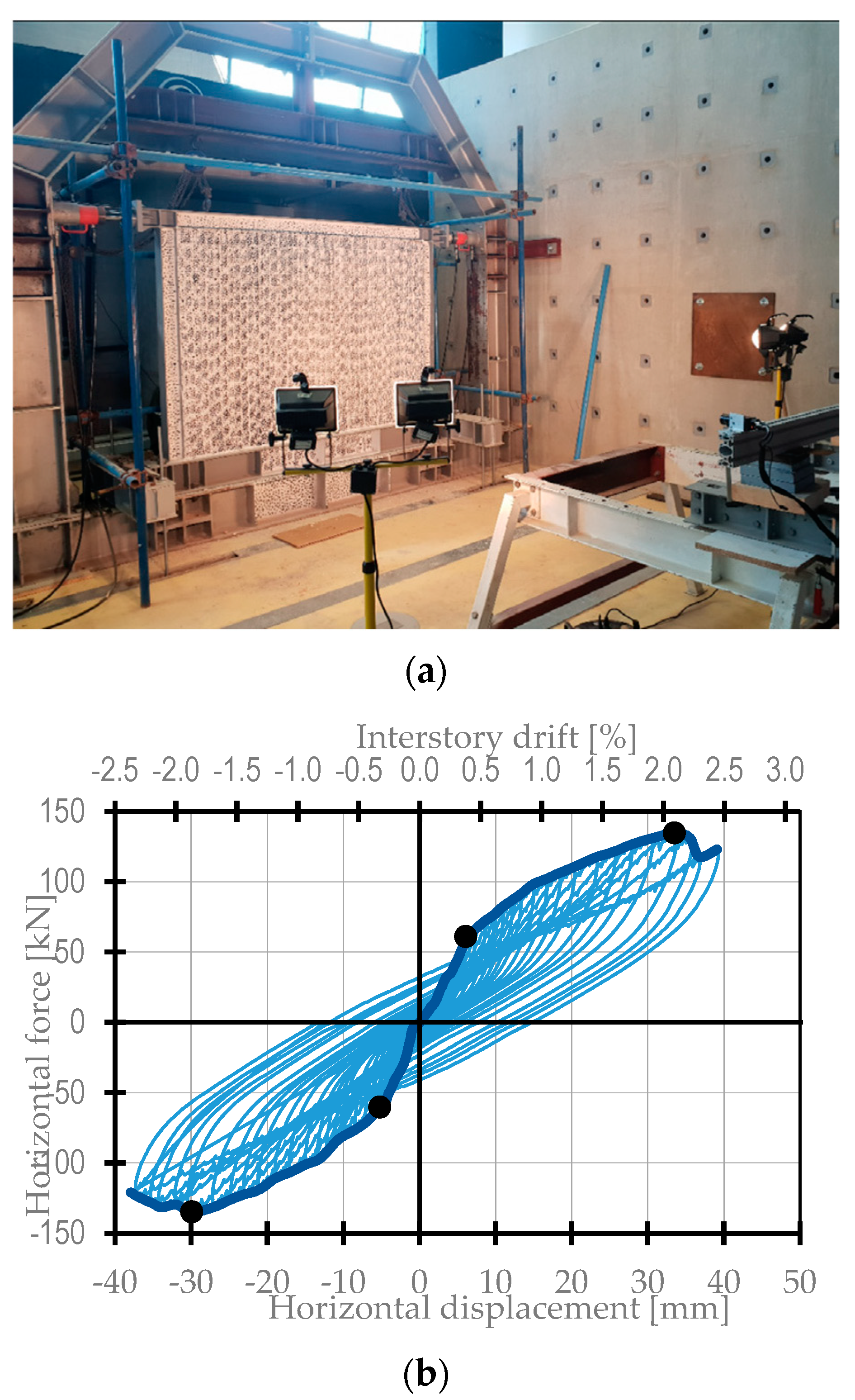
Results of testing of masonry wallets composed of RBC-EP blocks were presented in [6]. This included parallel to holes compressive and shear strength determination tests in accordance with EN 1052-1 [21] and EN 1052-3 [22], respectively. Mean parallel to holes compressive strength, elastic modulus, Poisson’s ratio, and initial shear strength were determined as 3.13 MPa, 2746 MPa, 0.20, and 0.15 MPa, respectively. Additional tests of perpendicular to holes compressive strength, based on principles for parallel to holes compressive tests listed in EN 1052-1 [21], revealed mean perpendicular to holes compressive strength and elastic modulus values to be 3.00 MPa and 3198 MPa, respectively. None of the constituents of masonry wallets were changed, and previous results were taken as relevant. Verification of results was performed by confirming that vertical compression results on wallets made of randomly sampled blocks from several batches are within 15% of 3.13 MPa. In order to approve the main hypothesis that masonry blocks with relatively lower stiffness and strength used as infill can be beneficial to the surrounding frame in regard to the interactive frame-infill behavior, various infilled steel frame (ISF) configurations were tested, and results were presented in [6]. The testing configuration and an example of obtained hysteresis loop for specimen ISO-RBC-EP are presented in Figure 3, with the results of testing given in Table 2.
The conclusion of the conducted testing from a structural point of view is that developed RBC-EP blocks showed notable potential for use as a frame infill. This is to be further complemented by thermal properties to gain full insight into the main characteristics of developed blocks, as well as their potential for application in practice. Since concrete itself has some weaknesses compared to other façade materials, such as high density, and high thermal conductivity [23], the next step was to measure thermal conductivity of RBC-EP blocks.

2.2. Measurements of Blocks Thermal Conductivity

Thermal conductivity of the material (W/mK) i.e., blocks used for building a real-sized wall, was measured in a laboratory by using a heat flow meter instrument. The following general instrument characteristics or requirement for conducting tests are taken from [24]:
  • Samples are placed between two plates in the test stack, and a temperature gradient is established over the thickness of the material;
  • The plates may be positioned either to a user-defined thickness, or using auto thickness, in which the instrument automatically moves to establish contact with the sample;
  • Thermocouples are attached directly to the sample surfaces, eliminating the impact of interface resistance, and improving the measurement accuracy for higher thermal conductivity samples (up to 2.5 W/mK).
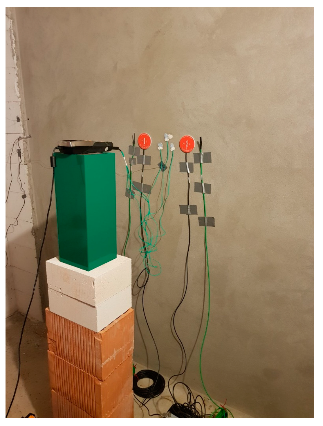
A Fox200 instrument was used in this research to determine thermal conductivity of blocks used for building a real-sized wall in a test chamber built inside the laboratory. Three samples were tested in instrument and external thermocouples were used (Figure 4). The surfaces of the test specimens were plane (sandpapering, cutting, and grinding are used), so that close contact between the specimens and the working surfaces could be obtained. After the determination of the mass of the specimen(s), they were conditioned to a constant mass in a ventilated oven at a temperature of 105 °C. After conditioning to a constant mass, the specimen(s) was cooled and stored in a sealed polyethylene bag. The specimens were removed, weighed, and installed in the apparatus immediately before testing. Measurements were conducted in compliance with ISO 8301:1991 Thermal insulation–Determination of steady-state thermal resistance and related properties–Heat flow meter apparatus. Measuring results are presented in Table 3.
Based on the results shown in Table 3, the thermal conductivity (λ) for concrete with RB and EP aggregate was 0.3789 W/(mK), and is in accordance with thermal conductivity of lightweight concretes. It is determined as an average value of thermal conductivity of all three samples. A lower coefficient of thermal conductivity indicates better thermal properties of concrete with RB and EP, as well as improved fire resistance. Notably, the slow rate of conductivity (heat transfer) enables concrete to act as an effective fire shield, not only between adjacent spaces, but also to protect itself from fire damage [25]. Previous research of concrete with RB aggregate also showed an improvement in fire resistance [26]. However, to confirm this advantage for masonry RB-EP blocks, testing the fire resistance of blocks is necessary. The values in Table 3 are given for the dry environmental conditions; when using these values in an analysis of the thermal properties of blocks, they should be calculated and converted into a designed coefficient of thermal conductivity independent of the actual state of humidity and temperature.

3. In Situ Measurements

3.1. Introduction

Research in laboratories is often performed with a guarded hot-box device, where two isolated chambers, one with a temperature-controlled cold chamber, and the other with a hot enclosure regulated in temperature or flow [27,28]. Research presented in this paper was performed in the test building, which was built inside an unheated laboratory. This made it possible to simulate not only outside temperature conditions during the measurements of walls U-values, but also compliance with the restrictions imposed by the standards. Those are unfavorable weather conditions—wind, solar radiation, and precipitation, which are discussed in next chapters. The two longer opposite sides of the building were constructed of 30 cm thick concrete thermal blocks, thermally insulated with 10 cm of expanded polystyrene, while the other two opposite sides of the building were constructed in a way that allowed for testing and alternating placement of different wall elements. In this research, a wall constructed of concrete blocks with recycled brick aggregate was analyzed, with consideration made to its thermal properties. Firstly, measurements were conducted on the wall without isolation, presented in Figure 5, and afterwards with isolation constructed from mineral wool (MW). In situ measurements included the measurement of test chamber airtightness, application of infrared thermography method on the wall, and measurements of the wall U-value through the standardized heat flow meter method (HFM) and non-standardized temperature-based method (TBM), which is currently being thoroughly investigated at the Faculty of Civil Engineering and Architecture, Osijek.

3.2. In-Situ Measurement of Airtightness and Infrared Thermography Method

When measuring the airtightness of buildings, a blower door method is used to find the relation between the pressure difference over the building envelope, ∆P [Pa], and the airflow rate through the building envelope, Q [m3/h] [29].
Measurements were performed to find typical air leakage places, which can negatively influence measurements of wall U-value; those places were found and straightened out to avoid unnecessary and unwanted heat loss through the wall. Leakages were found at the junction of the ceiling and floor of the examined wall, at the penetrations of the electrical installations through the walls, and leakages were found around and through the door. Airtightness in this research was measured by using a Minneapolis Blower Door, in accordance with EN ISO 9972:2015 [30], Method 1—the test of the building in use with the natural ventilation opening being closed, and the whole building mechanical ventilation or air conditioning opening being sealed (Figure 6). All experiments’ results and measurement values were acceptable, as they fulfil EN ISO 9972:2015 criteria, which requires that [31]:
  • All windows, doors, and trapdoors on the envelope are closed;
  • Ventilation openings in the envelope for natural ventilation are closed;
  • Openings for whole building mechanical ventilation or air conditioning are sealed;
  • Other intentional openings in the envelope including intermittent use mechanical ventilation or air conditioning shall be closed;
  • Small temperature differences;
  • Low wind speeds (wind speed near the ground exceeds 3 m/s, or the meteorological wind speed exceeds 6 m/s).
The first airtightness measurement result was n50 = 10.23 h−1, thus improvements of places where leakages were found were required. Those places in the test chamber and the wall itself were detected by using a smoking pen during the test. The second airtightness measurement result was n50 = 5.19 h−1 and was measured on non-insulated wall. The third airtightness measurement result was n50 = 4.98 h−1 and was performed on a wall insulated with mineral wool. From the first to the third measurement, the test chamber was heated from the inside. The difference between the second and third measurements can be explained by the fact that materials tend to expand due to exposure to high temperatures, and therefore seal smaller leakage areas, and by the fact that during the installation of thermal insulation, smaller cracks and openings were sealed.
The application of infrared thermography (IRT) in thermal diagnostics was commercialized in the 1990s [32]. IRT in building sector is used to qualitatively evaluate buildings and detect defects, [33] such as the thermal bridges applied in this research. Those defects were places where air leakage typically occurs [34,35,36,37], cracks [38], insulation continuity [35,39], thermal bridges [35,40,41], plaster detachment [42], moisture and condensation [36,38,43,44,45], delamination [38,46], defective services [39], and as a support when conducting thermal transmission measurements, with respect to the location of the instrument sensors [47,48,49]. It is important to avoid these places (or to remediate them) when placing sensors used in this research; these are the sensors used by the heat flow method (HFM) and temperature-based method (TBM) for estimating the thermal transmission properties of the wall.
The data required to carry out an IRT investigation include the emissivity factor, the reflective temperature, the atmospheric temperature, and relative humidity, while the temperature difference between the interior and the exterior of the investigated building is expected to be at least 10 °C [50].
When applying IRT, the investigated object should be in a steady-state condition to be free of disturbing influences. However, the building envelope is exposed to permanently changing meteorological conditions, and steady state conditions are seldom, if ever, met. IRT on external building elements should be performed either at night or during a cloudy day; this was found to be important in order to avoid the problem of temperature increase, which occurs as a result of the incident solar radiation, and the impact from the absorbed solar energy, which presents a time lag of a few hours [32]. Additionally, measurements should be carried at low wind speeds in order to minimize as much as possible the influence of convective heat losses [32]. Stated requirements were completely met in this research, since the test chamber was built inside an unheated laboratory—there was no solar radiation nor uncontrolled air flow inside the laboratory. A thermal imager Testo 882 was used in this research.

3.3. Measurements of the Thermal Transmission Properties

HFM is a non-destructive, standardized method used for estimating the thermal transmission properties of building elements. The HFM method is suitable for building elements perpendicular to the heat flow which have no significant lateral heat flow [48]. According to ISO 9869-1:2014 [48], the U-value measurement procedure is based on direct measurement of the heat flow rate and temperatures on both sides of the element under steady-state conditions. ISO 9869-1:2014 [48] proposes that measurements are conducted for at least three days to estimate the U-value of the element. Finally, when conducting measurements, the temperature difference should be greater than 10 °C, and should remain as constant as possible [51]. In this research, an instrument heat flux plate HFP01 sensor for heat flux measurement was used. Two sets of sensors were used to improve accuracy of measurements.
TBM is a relatively new and simple non-standardized method used to conduct in situ measurements of the U-value. The methodology behind this method is based on Newton’s Law of cooling, which states that the heat transfer rate is proportional to the temperature difference between a body and its surroundings and the area of the surface [52]. The U-value is calculated by using the following equation [52]:
U = h i T i T s i T i T e ,
where hi is the internal surface heat transfer coefficient, Ti is the indoor air temperature, Tsi is the indoor surface temperature, and Te is the external air temperature.
The main difference between TBM and the standardized HFM method relates to the way that the heat flux is determined. When conducting the HFM method, all parameters required to obtain the U-value are measured directly, and when TBM is employed, the heat flux is approximated by measuring the inside, outside, and inside wall surface temperatures [53]. In this research a Testo 435-4 instrument was used. The method is used to compare results with standardized method and theoretical values, since one of the research projects conducted at the Faculty is directed toward improvement of this method, and of its wider usage in practice.

4. Discussion

Since in situ U-value measurements must be conducted under a minimum temperature difference (the temperature difference should be greater than 10 °C) between the indoor and outdoor environment, the heating device was installed inside the chamber. Using the heating device, a minimum of 15 °C difference in temperature between indoor and outdoor was achieved during the measurement. The TFM method and TBM (Figure 7) were used to determine the U-values of the wall. To avoid the positioning of the sensors near by the thermal bridges and cracks, IRT was used (Figure 7). The upper IRT image in Figure 8 was taken during a cooling period (autumn/summer) to detect areas that should be avoided when placing instruments sensors, and the lower IRT image was taken during cooling period (winter). The upper image is on a wall without thermal insulation, and the lower one is a wall insulated with mineral wool. A heating and cooling device was used to obtain the minimal temperature difference required (15 °C) or higher.
Results presented in this chapter are for the period January 10th to March 24th, with a sampling interval of 10 min for measured data. The first set of measurements was conducted on a wall without thermal insulation (January 10th–February 14th), and a second set of measurements was performed on a wall insulated with mineral wool (March 10th–March 24th). The heating was turned on four months earlier, due to another testing, but in this case to also minimize the effects of the wall’s thermal storage. The average outside temperature for the first measurement period was 0.19 °C, inside 28.09 °C, which makes the average temperature difference during measurements of 27.90 °C. During the second measurement period, the average outside temperature was 29.86 °C, average inside temperature 9.15 °C, and the average temperature difference during measurements was 20.70 °C.
The results of the tested wall regarding in situ U-values obtained by measurements and theoretical U-values according to international standard ISO 6946:2017 are given in Table 4. Thermal conductivity of the blocks for theoretical calculations was used as described in previous chapter—the value measured in a laboratory by using a heat flow meter instrument. The simplification in calculation of theoretical values may contribute to the lower experimental U-value results for the uninsulated wall, and vice versa for the insulated wall.
Graphical presentation of the measurement results is rendered in Figure 9 and Figure 10 for two wall types—an uninsulated wall, and a wall with thermal insulation. Results in the Figures are given for both HFM sensors and for TBM.
Although differences in experimental and theoretical U-values are noticeable, a reduction in the U-value of insulated walls compared to uninsulated ones is similar regardless of the determination method used for obtaining the U-value. Graphs in Figure 9 and Figure 10 show how both experimental methods have the same trend of U-value shift during the measurement, which is especially evident when considering an insulated wall. Preliminary results of testing TBM in this research suggests that method is appropriate for isolated walls, and for uninsulated walls the correction factor is probably needed, and should be further investigated. Finally, to better understand the thermal characteristics of a wall constructed with masonry blocks consisting of self-compacting concrete with recycled crushed brick and ground polystyrene as an aggregate, a comparison of thermal properties with standard building materials used and found on the market was according to values from [54]:
  • hollow blocks made of lightweight concrete (HBLC), λ = 0.3700 W/mK;
  • hollow concrete blocks (HCB), λ = 1.4000 W/mK;
  • hollow clay blocks (HCLB), λ = 0.4800 W/mK.
Thermal conductivity values (W/mK) of those materials were taken from [48].A comparison of thermal conductivity values and other material properties between commonly used blocks on the market and new masonry blocks with recycled clay brick is presented in Table 5. Since block dimensions and weights vary, for more clear insight to different weight properties, the last column presents the overall weight of a wall that has a cubic shape, with a side length of 1 m.
Hollow blocks consisting of lightweight concrete have thermal conductivity very similar to RBC-EP blocks presented in this research, as was expected, since RBC-EP concrete was categorized as lightweight concrete in previous research [5]. The other two materials, hollow concrete blocks and hollow clay blocks, obtain thermal conductivities that are most often to be found when building—they do not have ingredients that improve their thermal properties. For selected materials, two theoretical analyses were performed, for uninsulated walls and for insulated walls. Results are presented in Table 6. The most interesting in this comparison is the fact that, after applying a thermal insulation of MW 10 cm thick, all U-values tend to get very similar, approximately 0.30 W/m2K which is, in Croatia, the maximum allowed value when constructing new or retrofitting old buildings.

5. Conclusions

This study investigates the thermal performance properties of real size wall made from new hollow masonry RBC-EP blocks by using experimental testing of materials used for building a wall and the wall itself, and a theoretical calculation of U-values as a main parameter for describing the thermal performance properties. The following conclusions can be drawn from presented research:
  • RBC-EP blocks comply to set goals of lower density, stiffness, and strength, combined with robustness and compactness, thus showing potential as an infill material for steel frames;
  • The desired structural behavior of steel frames infilled with RBC-EP blocks was experimentally tested and verified—infilled frames showed high ductility and robustness, along with increased strength and stiffness compared to bare steel frames, while, at the same time, preserving the frame from stronger detrimental effects typical for common masonry infill;
  • Thermal conductivity of RBC-EP is 0.3774 W/mK, which is similar to lightweight concrete;
  • Thermal properties of RBC-EP blocks are better than the thermal properties of commonly in use, HCB and HCLB, and are similar to HBLC;
  • Using new hollow masonry RBC-EP blocks does not affect a building’s airtightness values in negative way;
  • To avoid the placement of sensors near by the thermal bridges and cracks, IRT should be employed;
  • The results of testing TBM in this research suggest that the method is appropriate for isolated walls;
  • The experimental heat transfer coefficient of wall constructed with blocks is from 1.363 up to 1.782 W/m2K for an uninsulated wall, and the theoretical value is 2.01 W/m2K, which is better compared to hollow concrete blocks and hollow clay blocks.
Although there are similar lightweight concrete blocks, hollow normal concrete blocks, and hollow clay blocks on the market, the utilization of recycled crushed clay brick and EPS for the hollow concrete masonry block led to a lower carbon footprint, and their manufacture reduces industrial waste and natural resources consumption. The experimental research showed that the use of recycled clay brick and EP as a replacement for natural aggregate in concrete positively influenced the thermal conductivity of concrete. The lower content of cement and usage of recycled clay brick and EP leads to natural resource savings and reduces the mechanical properties. On the other hand, the lower mechanical properties may be suitable for application in infilled steel frames, as was explained above. Further research should be directed towards proving financial, economic, and ecological benefits of the presented new hollow masonry RBC-EP blocks. Moreover, research shows the potential of further development of TBM used for measuring U-values, and should be tested on walls constructed from different types of masonry blocks on uninsulated and insulated walls, since it is cheaper and easier to use compared to HFM.

Author Contributions

Conceptualization, H.K. and D.M.; methodology, H.K. and I.M.; software, M.D.; validation, H.K., D.M. and I.M.; formal analysis, H.K. and I.M.; investigation, M.D.; resources, H.K. and D.M.; writing—original draft preparation, H.K., D.M. and I.M.; writing—review and editing, H.K., D.M. and I.M.; visualization, H.K.; supervision, D.M.; project administration, H.K. and D.M.; funding acquisition, H.K. and D.M. All authors have read and agreed to the published version of the manuscript.

Funding

This paper is a part of the projects entitled “Evaluation of experimental methods for the determination of the U-value in steady state conditions” and “Controlled seismic behavior of steel frames with masonry infill”, supported by the Faculty of Civil Engineering and Architecture Osijek.

Institutional Review Board Statement

Not applicable.

Informed Consent Statement

Not applicable.

Data Availability Statement

The data presented in this study are available on request from the corresponding author.

Conflicts of Interest

The authors declare no conflict of interest.

References

  1. Kolokotsa, D.; Diakaki, C.; Grigoroudis, E.; Stavrakakis, G.; Kalaitzakis, K. Decision support methodologies on the energy efficiency and energy management in buildings. Adv. Build. Energy Res. 2009, 3, 121–146. [Google Scholar] [CrossRef]
  2. Mickaityte, A.; Zavadskas, E.K.; Kaklauskas, A.; Tupenaite, L. The concept model of sustainable buildings refurbishment. Int. J. Strateg. Property Manag. 2008, 12, 53–68. [Google Scholar] [CrossRef]
  3. Blanco, J.M.; Frómeta, Y.G.; Madrid, M.; Cuadrado, J. Thermal performance assessment of walls made of three types of sustainable concrete blocks by means of fem and validated through an extensive measurement campaign. Sustainability 2021, 13, 386. [Google Scholar] [CrossRef]
  4. Sakir, S.; Raman, S.N.; Safiuddin, M.; Kaish, A.B.M.; Mutalib, A.A. Utilization of By-Products and Wastes as Supplementary Cementitious Materials in Structural Mortar for Sustainable Construction. Sustainability 2020, 12, 3888. [Google Scholar] [CrossRef]
  5. Markulak, D.; Dokšanović, T.; Radić, I.; Miličević, I. Structurally and environmentally favorable masonry units for infilled frames. Eng. Struct. 2018, 175, 753–764. [Google Scholar] [CrossRef]
  6. Markulak, D.; Dokšanović, T.; Radić, I.; Zovkić, J. Behaviour of steel frames infilled with environmentally and structurally favourable masonry units. Eng. Struct. 2020, 204, 109909. [Google Scholar] [CrossRef]
  7. Jakumetović, A.; Markulak, D.; Miličević, I. Properties of low strength self-compacting concrete with recycled brick as aggregate. In Proceedings of the 1st International Conference on Construction Materials for Sustainable Future 2017, Zadar, Croatia, 19–21 April 2017; pp. 243–249. [Google Scholar]
  8. Markulak, D.; Radić, I.; Sigmund, V. Cyclic testing of single bay steel frames with various types of masonry infill. Eng. Struct. 2013, 51, 267–277. [Google Scholar] [CrossRef]
  9. Pavlu, T.; Fortova, K.; Divis, J.; Hajek, P. The utilization of recycled masonry aggregate and recycled eps for concrete blocks for mortarless masonry. Materials 2019, 12, 1923. [Google Scholar] [CrossRef] [Green Version]
  10. European Committee for Standardization (CEN). EN 12390-3, Testing Hardened Concrete—Part 3: Compressive Strength of Test Specimens; CEN: Brussels, Belgium, 2009. [Google Scholar]
  11. European Committee for Standardization (CEN). EN 12390-5, Testing Hardened Concrete—Part 5: Flexural Strength of Test Specimens; CEN: Brussels, Belgium, 2009. [Google Scholar]
  12. European Committee for Standardization (CEN). EN 12390-7, Testing Hardened Concrete— Part 7: Density of Hardened Concrete; CEN: Brussels, Belgium, 2009. [Google Scholar]
  13. European Committee for Standardization (CEN). EN 12390-2, Testing Hardened Concrete—Part 2: Making and Curing Specimens for Strength Tests; CEN: Brussels, Belgium, 2009. [Google Scholar]
  14. Al-Tamimi, A.S.; Al-Amoudi, O.S.B.; Al-Osta, M.A.; Ali, M.R.; Ahmad, A. Effect of insulation materials and cavity layout on heat transfer of concrete masonry hollow blocks. Constr. Build. Mater. 2020, 254, 119300. [Google Scholar] [CrossRef]
  15. European Committee for Standardization (CEN). EN 772-2, Methods of Test for Masonry Units—Part 2: Determination of Percentage Area of Voids in Aggregate Concrete Masonry Units; CEN: Brussels, Belgium, 1998. [Google Scholar]
  16. European Committee for Standardization (CEN). EN 772-16, Methods of Test for Masonry Units—Part 16: Determination of Dimensions; CEN: Brussels, Belgium, 2011. [Google Scholar]
  17. European Committee for Standardization (CEN). EN 12350-6, Testing Fresh Concrete—Part 6: Density; CEN: Brussels, Belgium, 2009. [Google Scholar]
  18. European Committee for Standardization (CEN). EN 12350-7, Testing Fresh Concrete—Part 7: Air Content—Pressure Methods; CEN: Brussels, Belgium, 2009. [Google Scholar]
  19. European Committee for Standardization (CEN). EN 12350-8, Testing Fresh Concrete—Part 8: Self-COMPACTING Concrete—Slump-Flow Test; CEN: Brussels, Belgium, 2010. [Google Scholar]
  20. European Committee for Standardization (CEN). EN 12350-12, Testing Fresh Concrete—Part 12: Self-Compacting Concrete—J-Ring Test; CEN: Brussels, Belgium, 2010. [Google Scholar]
  21. European Committee for Standardization (CEN). EN 1052-1, Methods of Test for Masonry—Part 1: Determination of compressive Strength; CEN: Brussels, Belgium, 1998. [Google Scholar]
  22. European Committee for Standardization (CEN). EN 1052-3, Methods of Test for Masonry—Part 3: Determination of Initial Shear Strength; CEN: Brussels, Belgium, 2008. [Google Scholar]
  23. Madrid, M.; Orbe, A.; Rojí, E.; Cuadrado, J. The effects of by-products incorporated in low-strength concrete for concrete masonry units. Constr. Build. Mater. 2017, 153, 117–128. [Google Scholar] [CrossRef]
  24. TA Instruments WEB Site. Available online: https://www.tainstruments.com/fox-200/ (accessed on 23 September 2021).
  25. Mineral Products Association (MPA). Performance of Concrete Structures in Fire; MPA—The Concrete Centre: Maidenhead, UK, 2011; ISBN 978-1-904818-83. [Google Scholar]
  26. Netinger, I.; Kesegic, I.; Guljas, I. The effect of high temperatures on the mechanical properties of concrete made with different types of aggregates. Fire Saf. J. 2011, 46, 425–430. [Google Scholar] [CrossRef]
  27. Madrid, M.; Orbe, A.; Carré, H.; García, Y. Thermal performance of sawdust and lime-mud concrete masonry units. Constr. Build. Mater. 2018, 169, 113–123. [Google Scholar] [CrossRef]
  28. Wakili, K.G.; Tanner, C. U-value of a dried wall made of perforated porous clay bricks: Hot box measurement versus numerical analysis. Energy Build. 2003, 35, 675–680. [Google Scholar] [CrossRef]
  29. Relander, T.-O.; Holøs, S.; Thue, J.V. Airtightness estimation—A state of the art review and an en route upper limit evaluation principle to increase the chances that wood-frame houses with a vapour- and wind-barrier comply with the airtightness requirements. Energy Build. 2012, 54, 444–452. [Google Scholar] [CrossRef]
  30. ISO 9972:2015. Thermal Performance of Buildings—Determination of Air Permeability of Buildings—Fan Pressurization Method; ISO: Geneva, Switzerland, 2015. [Google Scholar]
  31. Sfakianaki, A.; Pavlou, K.; Santamouris, M.; Livada, I.; Assimakopoulos, M.N.; Mantas, P.; Christakopoulos, A. Air tightness measurements of residential houses in Athens, Greece. Build. Environ. 2008, 43, 398–405. [Google Scholar] [CrossRef]
  32. Fokaides, P.A.; Kalogirou, S.A. Application of infrared thermography for the determination of the overall heat transfer coefficient (U-Value) in building envelopes. Appl. Energy 2011, 88, 4358–4365. [Google Scholar] [CrossRef]
  33. Fox, M.; Goodhew, S.; De Wilde, P. Building defect detection: External versus internal thermography. Build. Environ. 2016, 105, 317–331. [Google Scholar] [CrossRef] [Green Version]
  34. Kalamees, T. Air tightness and air leakages of new lightweight single-family detached houses in Estonia. Build. Environ. 2007, 42, 2369–2377. [Google Scholar] [CrossRef]
  35. Taylor, T.; Counsell, J.; Gill, J. Energy efficiency is more than skin deep: Improving construction quality control in new-build housing using thermography. Build. Environ. 2013, 66, 222–231. [Google Scholar] [CrossRef]
  36. Gonçalves, M.D.; Colantonio, T. Commissioning of Exterior Building Envelopes of Large Buildings for Resultant Moisture Accumulation Using Infrared Thermography and Other Diagnostic Tools. Therm. Perform. Exter. Envel. 2007, 7, 1–10. [Google Scholar]
  37. Lerma, C.; Barreira, E.; Almeida, R.M.S.F. A discussion concerning active infrared thermography in the evaluation of buildings air infiltration. Energy Build. 2018, 168, 56–66. [Google Scholar] [CrossRef]
  38. Kilic, G. Using advanced NDT for historic buildings: Towards an integrated multidisciplinary health assessment strategy. J. Cult. Herit. 2015, 16, 526–535. [Google Scholar] [CrossRef]
  39. Titman, D.J. Applications of thermography in non-destructive testing of structures. NDT E Int. 2001, 34, 149–154. [Google Scholar] [CrossRef]
  40. Hopper, J.; Littlewood, J.R.; Taylor, T.; Counsell, J.A.; Thomas, A.M.; Karani, G.; Evans, N.I. Assessing retrofitted external wall insulation using infrared thermography. Struct. Surv. 2012, 30, 245–266. [Google Scholar] [CrossRef]
  41. Taileb, A.; Dekkiche, H. Infrared imaging as a means of analyzing and improving energy efficiency of building envelopes: The case of a LEED Gold Building. Procedia Eng. 2015, 118, 639–646. [Google Scholar] [CrossRef]
  42. de Freitas, S.S.; de Freitas, V.P.; Barreira, E. Detection of façade plaster detachments using infrared thermography—A nondestructive technique. Constr. Build. Mater. 2014, 70, 80–87. [Google Scholar] [CrossRef]
  43. Kominsky, J.R.; Luckino, J.; Martin, T. Passive infrared thermography—a qualitative method for detecting moisture anomalies in building envelopes. Tedford Pond 2007, 2005, 1–11. [Google Scholar]
  44. Barreira, E.; Almeida, R.M.S.F.; Delgado, J.M.P.Q. Infrared thermography for assessing moisture related phenomena in building components. Constr. Build. Mater. 2016, 110, 251–269. [Google Scholar] [CrossRef]
  45. Grinzato, E.; Bison, P.G.; Marinetti, S. Monitoring of ancient buildings by the thermal method. J. Cult. Herit. 2002, 3, 21–29. [Google Scholar] [CrossRef]
  46. Edis, E.; Flores-Colen, I.; De Brito, J. Building thermography: Detection of delamination of adhered ceramic claddings using the passive approach. J. Nondestr. Eval. 2014, 34, 268. [Google Scholar] [CrossRef]
  47. Walker, R.; Pavía, S. Thermal performance of a selection of insulation materials suitable for historic buildings. Build. Environ. 2015, 94, 155–165. [Google Scholar] [CrossRef]
  48. International Organization for Standardization. Thermal Insulation—Building Elements—In-Situ Measurement of Thermal Resistance and Thermal Transmittance—Part 1: Heat Flow Meter Method; ISO: Geneva, Switzerland, 2014. [Google Scholar]
  49. Thermal Performance of Buildings—Qualitative Detection of Thermal Irregularities in Building Envelopes—Infrared Method; ISO: Geneva, Switzerland, 1983.
  50. Kylili, A.; Fokaides, P.A.; Christou, P.; Kalogirou, S.A. Infrared thermography (IRT) applications for building diagnostics: A review. Appl. Energy 2014, 134, 531–549. [Google Scholar] [CrossRef]
  51. Trethowen, H. Measurement errors with surface-mounted heat flux sensors. Build. Environ. 1986, 21, 41–56. [Google Scholar] [CrossRef]
  52. Çengel, Y.A. Heat Transfer: A Practical Approach; McGraw-Hill: New York, NY, USA, 2004. [Google Scholar]
  53. Teni, M.; Krstić, H.; Kosiński, P. Review and comparison of current experimental approaches for in-situ measurements of building walls thermal transmittance. Energy Build. 2019, 203, 109417. [Google Scholar] [CrossRef]
  54. Narodne Novine. Tehnički Propis o Racionalnoj Uporabi Energije i Toplinskoj Zaštiti u Zgradama (Translation: Technical Regulation on the Rational Use of Energy and Thermal Insulation in Buildings); Narodne Novine: Zagreb, Croatia, 2020. [Google Scholar]
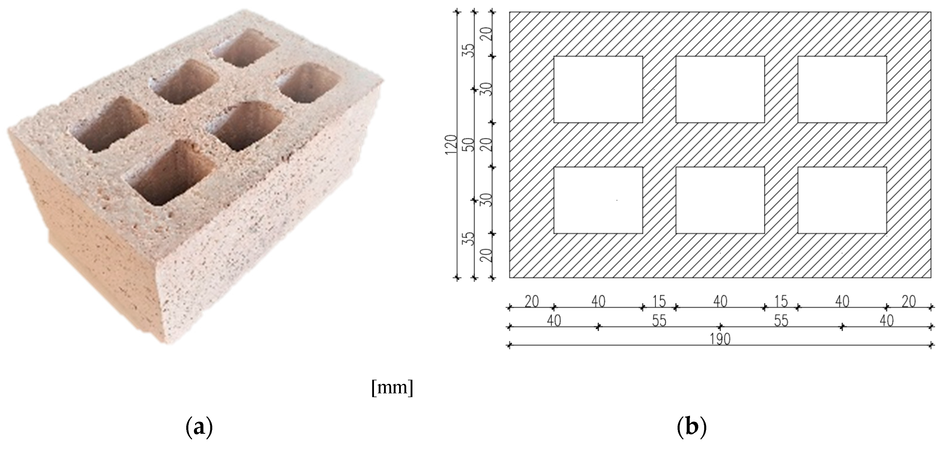
Figure 1. Concrete masonry block– RBC-EP (a) photo of the block, (b) block dimension in mm.
Buildings 11 00584 g001
Figure 2. Flowchart of the experimental investigation.
Buildings 11 00584 g002
Figure 3. Testing configuration (a) instrumentation setup, (b) example of hysteresis loop [4].
Buildings 11 00584 g003
Figure 4. Measurements of blocks thermal conductivity (a) tested samples, (b) preparation for measurement in Fox200 instrument.
Buildings 11 00584 g004
Figure 5. Wall made of RBC-EP masonry block—without isolation.
Buildings 11 00584 g005
Figure 6. Blower door equipment installed and measurements of test chamber airtightness in progress.
Buildings 11 00584 g006
Figure 7. HF method and TBM used for measurement of thermal transmittance of tested wall—interior of tested wall.
Buildings 11 00584 g007
Figure 8. IR thermography (a) IRT image during a cooling period (autumn/summer), (b) wall without thermal insulation, (c) IRT image during cooling period (winter), (d) wall insulated with mineral wool.
Buildings 11 00584 g008
Figure 9. Measured U-values for a wall without thermal insulation for the period January 10th–February 14th.
Buildings 11 00584 g009
Figure 10. Measured U-values for a wall with thermal insulation for the period March 10th–March 24th.
Buildings 11 00584 g010
Table 1. RBC-EP blocks mixture composition and characteristics [3,4].
Composition (kg/m3)Fresh stateViscosity ClassVS2
w/b0.47Density ρ (kg/m3)1730
w/p0.99Air content (%)8.0
Cement200Slump-flow test T500 (s)4.8
Lime255J-ring test (mm)9.25
Water215Hardened stateDensity classD.1.4
AdditiveSP2%CS
fc (MPa)
5.36
VMA0.5%FS
fcf (MPa)
2.34
AEA1%Density
ρ (kg/m3)
1396
FillerBP137Concrete masonry unit RBC-EPDimensions
(mm)
190 × 120 × 90
FineRB346Mean compressive strength
fm (MPa)
4.06
GEP9.6Normalized compressive strength
fb (MPa)
2.99
CoarseRB262Mean gross dry density
(kg/m3)
847.95
Note: 1 slugs/ft3 = 515.32 kg/m3; 1 in = 25.4 mm; 1 ksi = 6.89 MPa; w/b = water to binder ratio; w/p = water to powder ratio; SP = superplasticizer; WMA = viscosity modifying admixture; AEA = air-entraining admixture; BP = brick dust; RB = crushed clay bricks; GEP = ground expanded polystyrene; CS = compressive strength; FS = flexural strength.
Table 2. Experimental results [4].
Test ConfigurationISF-RBC-EP
Loading direction+
Initial stiffnessS0 (kN/mm)14.415.7
Change of initial stiffnessFy (kN)69.569.0
dy (mm)8.17.6
DRy (%)0.50.5
Ultimate loadFu (kN)130.0130.0
du (mm)48.730.2
DRu (%)3.01.9
Ultimate driftFdmax (kN)130.090.0
dmax (mm)48.737.1
DRdmax (%)3.02.3
Note: 1 ksi = 6.89 MPa; 1 inch = 25.4 mm.
Table 3. Thermal conductivity of RBC-EP blocks–measurement results.
ValuesSample 1Sample 2Sample 3
Setpoint Upper Plate15.00 °C15.00 °C15.00 °C
Setpoint Lower Plate25.00 °C25.00 °C25.00 °C
Results Average-Thermal conductivity [W/mK]
Temperature Average 20 °C
0.38170.38070.3835
Results Average - Thermal conductivity [W/mK]
Temperature Average 15 °C
0.37870.37730.3800
Results Average-Thermal conductivity [W/mK]
Temperature Average 10 °C
0.37620.37430.3776
Average value of Thermal conductivity [W/mK]0.37890.37740.3804
Table 4. An overview of results in situ U-values obtained by measurements and theoretical U-values.
Wall TypeMeasurement PeriodHFM Method Sensor Set 1HFM Method Sensor Set 2TBMTheoretical U-Value
U [W/m2K]
Uninsulated wall composition:
1 cm thick plaster (λplaster = 1.000 W/mK)
12 cm thick wall (λblock = 0.3789 W/mK)
10.1.2020.–24.1.2020.1.7401.7821.3632.01
Wall with thermal insulation composition:
1 cm thick plaster (λplaster = 1.000 W/mK)
12 cm thick wall (λblock = 0.3789 W/mK)
10 cm thick insulation (λMW = 0.035 W/mK)
10.3.2020.–24.3.2020.0.5160.4650.4570.30
Difference in values on uninsulated and insulated wall [%]70%74%66%85%
Table 5. Comparison of properties between commonly used blocks on the market and new masonry blocks with recycled clay brick.
Type of Block–Vertical HollowsDimensions (mm)Normalized Compressive Strength
fb (MPa)
Thermal Conductivity (W/mK)Weight (kg/unit)Overall Mass of 1 m3 of Wall (kg)
Hollow clay blocks (HCLB)250 × 190 × 1906.510.4800141554
Hollow blocks made of lightweight concrete (HBLC)625 × 200 × 1002.600.370010800
Hollow concrete blocks (HCB)200 × 200 × 4006.501.4000171071
Concrete with recycled crushed brick and ground polystyrene (RBC-EP)190 × 120 × 902.990.37892.501220
Table 6. Comparison of theoretical U-values of uninsulated and insulated walls when using different types of building materials.
Wall TypeMasonry Wall–RBC-EP BlockMasonry Wall–HBLCMasonry Wall–HCBMasonry Wall–HCLB
Theoretical U-Value
[W/m2K] for Uninsulated Wall
2.011.983.762.33
Theoretical U-Value
[W/m2K] for Insulated Wall
0.300.300.320.30
Publisher’s Note: MDPI stays neutral with regard to jurisdictional claims in published maps and institutional affiliations.