Article

Optimizing Photoelectrochemical UV Imaging Photodetection: Construction of Anatase/Rutile Heterophase Homojunctions and Oxygen Vacancies Engineering in MOF-Derived TiO2

1
School of Science, Harbin University of Science and Technology, Harbin 150080, China
2
School of Materials Science and Chemical Engineering, Harbin University of Science and Technology, Harbin 150080, China
3
Department of Opto-Electronic Information Science, School of Materials Science and Engineering, Harbin Institute of Technology, Harbin 150080, China
4
Tianjin Jinhang Technical Physics Institute, Tianjin 300308, China
*
Authors to whom correspondence should be addressed.
Molecules 2024, 29(13), 3096; https://doi.org/10.3390/molecules29133096
Submission received: 31 May 2024 / Revised: 22 June 2024 / Accepted: 26 June 2024 / Published: 28 June 2024
(This article belongs to the Special Issue Recent Progress in Nanomaterials in Electrochemistry)

Abstract

:
Self-powered photoelectrochemical (PEC) ultraviolet photodetectors (UVPDs) are promising for next-generation energy-saving and highly integrated optoelectronic systems. Constructing a heterojunction is an effective strategy to increase the photodetection performance of PEC UVPDs because it can promote the separation and transfer of photogenerated carriers. However, both crystal defects and lattice mismatch lead to deteriorated device performance. Here, we introduce a structural regulation strategy to prepare TiO2 anatase-rutile heterophase homojunctions (A-R HHs) with oxygen vacancies (OVs) photoanodes through an in situ topological transformation of titanium metal–organic framework (Ti-MOF) by pyrolysis treatment. The cooperative interaction between A-R HHs and OVs suppresses carrier recombination and accelerates carrier transport, thereby significantly enhancing the photodetection performance of PEC UVPDs. The obtained device realizes a high on/off ratio of 10,752, a remarkable responsivity of 24.15 mA W−1, an impressive detectivity of 3.28 × 10¹¹ Jones, and excellent cycling stability. More importantly, under 365 nm light illumination, a high-resolution image of “HUST” (the abbreviation of Harbin University of Science and Technology) was obtained perfectly, confirming the excellent optical imaging capability of the device. This research not only presents an advanced methodology for constructing TiO2-based PEC UVPDs, but also provides strategic guidance for enhancing their performance and practical applications.

1. Introduction

Ultraviolet photodetectors (UVPDs) capable of converting perceived light signals into electrical ones have attracted widespread attention with applications in photocontrol switches, environmental monitoring, biological analysis, and optical sensing imaging [1,2]. Among them, photoelectrochemical (PEC) UVPDs not only exhibit outstanding sensitivity but also circumvent the complex photolithography process associated with the fabrication of UVPDs based on the p-n junction or Schottky junction. Moreover, PEC UVPDs are capable of attaining a self-powered operation mode using the interfacial electric field between semiconductors and electrolytes, rendering them an ideal selection for wireless integrated energy-saving optoelectronic systems. Recently, TiO2 has been extensively employed as a photosensitive material in self-powered PEC UVPDs due to its facile nanostructure modification, low cost, security, and environmental friendliness [3]. However, current PEC UVPDs relying on pure TiO2 exhibit low light-harvesting capabilities, inadequate separation and transportation of photogenerated carriers, and interfacial charge recombination losses, which impact their performance and stability. As such, there is an urgent need for innovative TiO2 photoanode architectures that can suppress interfacial charge recombination while facilitating carrier transport, aiming to enhance the practical applications of PEC UVPDs.
Optimizing the nanostructure of TiO2 photoanodes by morphology, porous modification, and hierarchical architecture offers advantages such as improving the specific surface area of the nanostructures and inducing multiple refractions of light, making them suitable for enhancing light-harvesting efficiency [4,5,6,7]. However, the agglomeration of the nanostructure impedes their development, as such strategies increase the charge transfer pathway and lead to obstruction of charge transport within the materials. Coating TiO2 with conductive networks of graphene, MXenes, and polymers is ideal for PEC UVPDs. These networks act as a scaffold, facilitating charge transport in the TiO2 films [8]. However, the poor attachment between the TiO2 nanostructures and conductive networks makes them susceptible to increased charge transfer resistance when exposed to electrolyte environments. Furthermore, the high density of surface states within conductive networks leads to nonradiative carrier recombination, posing challenges to further enhancing the photodetection performance of the devices [9]. Recently, researchers have attempted to couple different semiconductors to form heterojunctions with energy barriers and interfacial effects to enhance light harvesting and charge separation [10]. However, the passivation of effective nucleation during heterojunction growth leads to an increase in crystal defects, increasing the dark current of PEC UVPDs. Moreover, the lattice stress and strain induced by the lattice mismatch at the junction could impair the photodetection performance of the devices [11]. In this regard, leveraging the diverse crystal structures of TiO2 to develop anatase-rutile (A-R) heterophase homojunctions (HHs) holds promise as a strategy to overcome these issues [12,13,14]. The literature has reported that oxygen vacancies (OVs) can act as electron donors to promote the transfer of photogenerated carriers, which increases the conductivity and charge transport of TiO2, thus enhancing the photodetection performance of devices [15]. Therefore, the simple and rational preparation of TiO2 A-R HHs with OVs and their application in photoanodes are of great significance for engineering high-performance PEC UVPDs.
Here, we propose a strategy to utilize the in situ topological conversion process of titanium metal–organic frameworks (Ti-MOFs) for preparing MOF-derived TiO2 A-R HHs enriched with OVs and enhancing the photodetection performance of TiO2-based PEC UVPDs. The moderate OVs and the Type II band alignment of A-R HHs contribute to the enhanced separation of photogenerated electron-hole pairs in TiO2. More importantly, we verify that the presence of a barrier layer in the built-in electric field of TiO2 A-R HHs effectively reduces the recombination loss of photogenerated carriers with I3 in the Helmholtz layer. Benefiting from the combined impact of improving the separation of photogenerated electron-hole pairs and reducing carrier recombination, the resulting device achieves a high on/off ratio of 10,752, a remarkable responsivity of 24.15 mA W−1, an impressive detectivity of 3.28 × 10¹¹ Jones, and excellent cycling stability under 365 nm irradiation at 0 V bias. Validating the application, the device integrated into the optical system as the sensing pixel achieves excellent high-resolution imaging, providing robust support for the future development of high-performance, multifunctional optoelectronic systems.

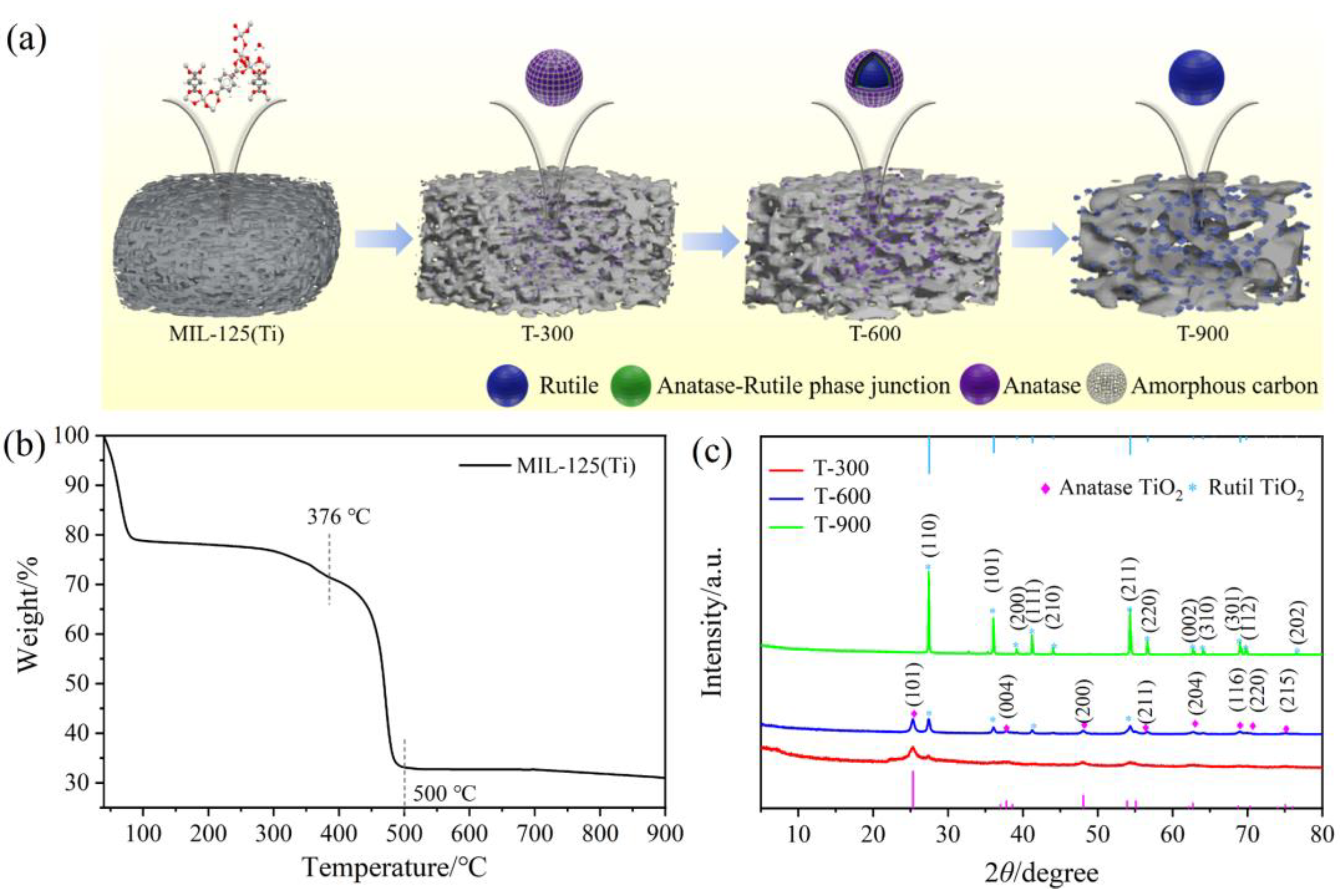
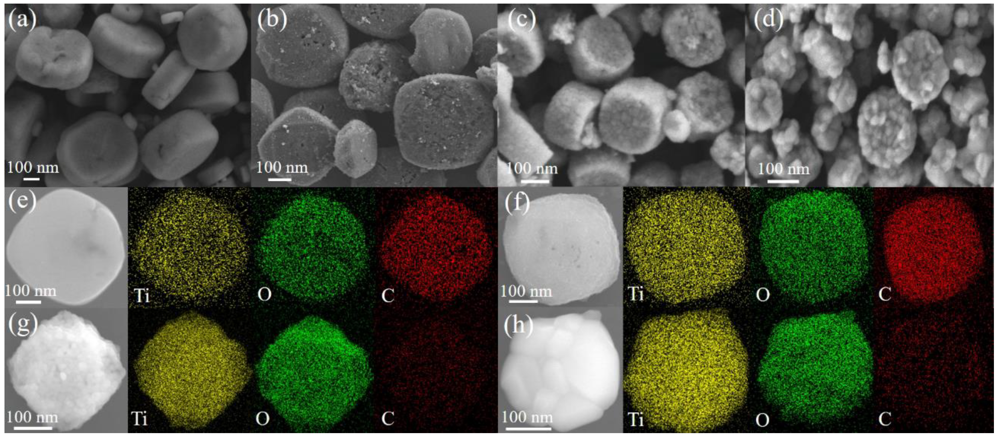
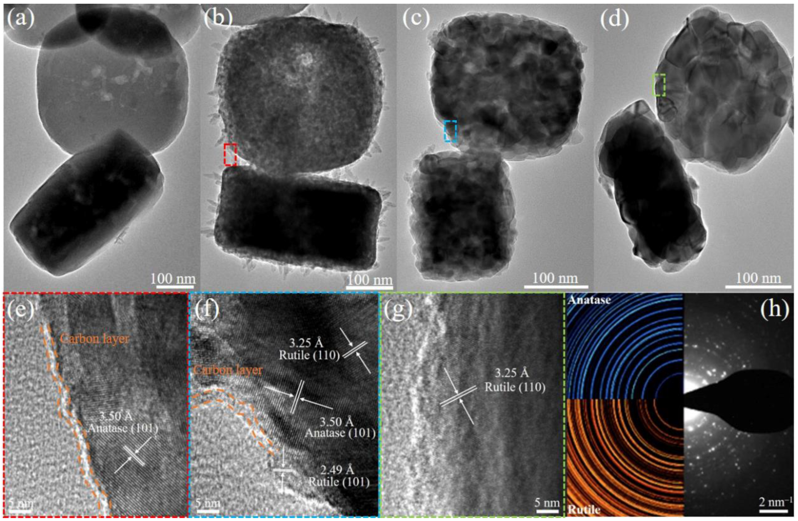
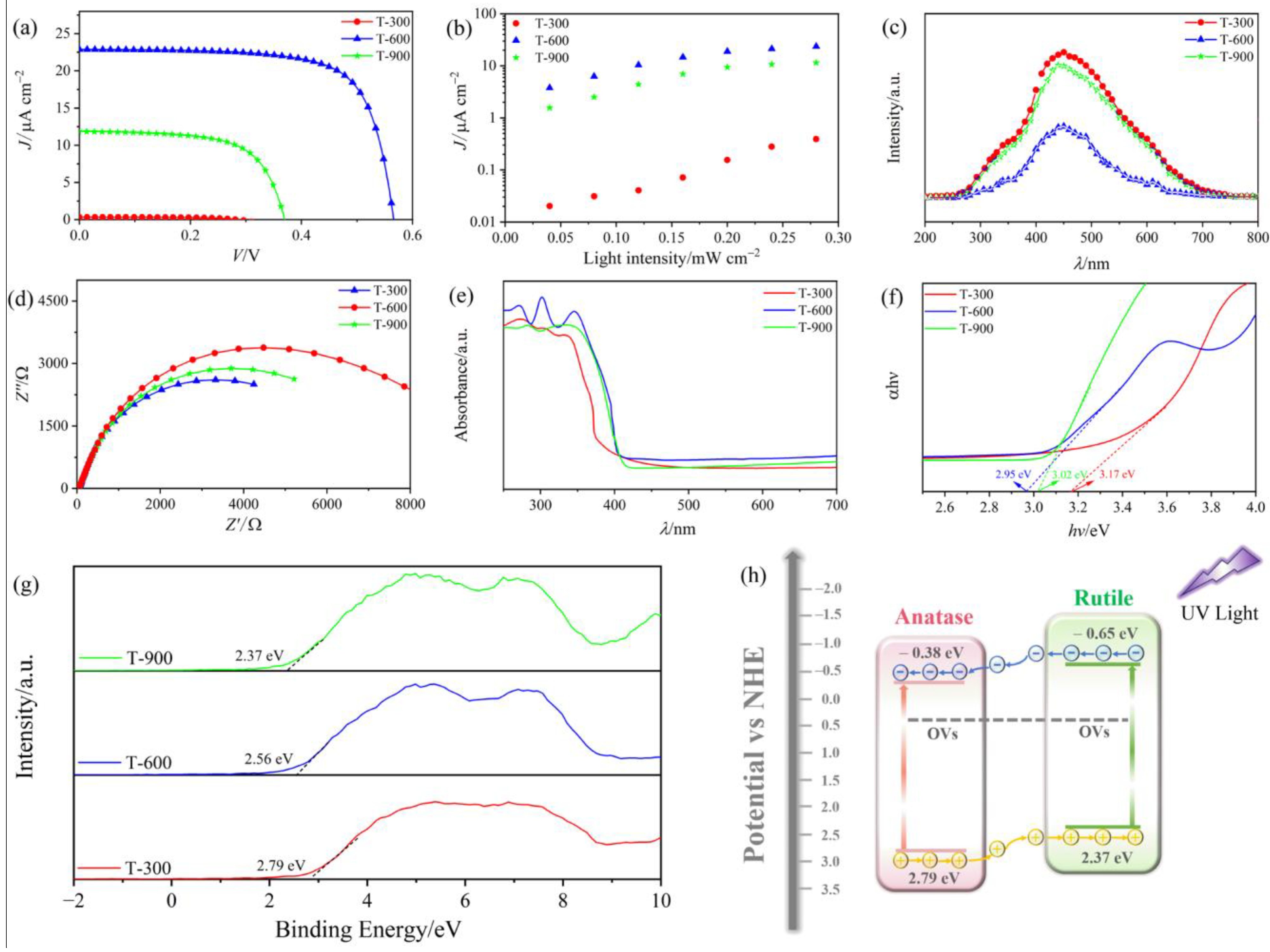
2. Results and Discussion

The plausible growth procedure, featuring an in situ topological conversion strategy for MOF-derived TiO2 A-R HHs, is illustrated in Figure 1a. During the initial stage, mooncake-like MIL-125(Ti) was fabricated and employed as templates. Then, the formed Ti-MOF decomposed into TiO2 A-R HHs, while the organic linkers created a porous carbon matrix during pyrolysis treatment [16]. The crystallographic structure of the as-synthesized MIL-125(Ti) was examined by XRD analysis. As shown in Figure S1, the distinct peaks of the as-synthesized MIL-125(Ti) match well with the simulated XRD patterns, indicating the formation of pure phase MIL-125(Ti). To better understand the transition of MIL-125(Ti) into TiO2 as the temperature increases, TG analysis was performed up to 900 °C, as illustrated in Figure 1b. The initial weight loss of approximately 21% up to 100 °C is attributed to the removal of adsorbed gases and the vaporization of solvents or water molecules from the pores of Ti-MOF [17]. A subsequent weight loss of 9.2% around 376 °C corresponds to the breaking of coordination bonds between the organic linker and the Ti oxo-cluster [18]. At around 550 °C, a substantial 66% mass loss occurs primarily due to the decomposition of the organic ligand along with the disintegration of the framework structure [19]. Notably, the prepared MIL-125(Ti) shows a slight weight loss between 550 and 900 °C, indicating that a small quantity of carbon from the organic linker is retained in the MOF-derived TiO2.
As shown in Figure 1c, the diffraction peaks of T-300 display only broad and weak characteristics of A-phase TiO2 (JCPDS No. 21-1272), which suggests the possible presence of a substantial layer of carbon on the TiO2 matrix surfaces or the formation of TiO2 nanoparticles (NPs) with relatively low crystallinity [20]. The favored formation of the A-phase at lower pyrolysis temperatures can be understood through its structural characteristics. The unit cell of the A-phase, known for its long-range order, experiences minimal molecular restriction during the nucleation process, promoting its formation at temperatures lower than that required for the R-phase [21]. From a thermodynamic perspective, the lower temperature formation of the A-phase can be attributed to the differences in the Gibbs free energy. During nucleation, the A-phase exhibits a smaller change in surface-free energy than the R-phase of TiO2, indicating that it requires less energy from the surroundings to establish a stable nucleation surface. Therefore, the A-phase is more likely to form at lower temperatures compared to the R-phase [22]. With an increase in the pyrolysis temperature to 600 °C, the observed peaks at 2θ of 25.28°, 37.8°, 48.05°, 55.06°, 62.69°, 68.76°, 70.31°, and 75.03° correspond to the (101), (004), (200), (211), (204), (116), (220), and (215) crystal planes of A-phase TiO2 (JCPDS No. 21-1272), respectively. Furthermore, the diffraction peaks around 27.4°, 36.08°, 41.23°, and 54.33° align with those of R-phase TiO2 (JCPDS No. 21-1276), confirming the successful preparation of TiO2 A-R HHs in the T-600 sample. For the T-900 sample, the diffraction peaks of the R-phase were notably enhanced, while those associated with the A-phase were no longer detectable, confirming the transformation of MOF-derived TiO2 from a low-crystallinity metastable A-phase to a crystalline R-phase. Moreover, no additional peaks corresponding to carbon (JCPDS No. 75-0444) were detected in the T-600 and T-900 samples, indicating the formation of strong bonds between carbon and TiO2 during the pyrolysis process.
The A-phase to R-phase ratio (WA/WR, %) values for the obtained samples can be determined by calculating the peak intensity using the following formula [23] (as listed in Table 1):
W A = K A I A K A I A + I R
W R = 1 W A
where KA is a coefficient with a value of 0.886, and WA and WR represent the relative contents of A-phase and R-phase, respectively. IA and IR correspond to the A-phase (110) and R-phase (101) diffraction peak areas, respectively. This reveals that an increase in pyrolysis temperature leads to a gradual increase in the content of the R-phase, which is likely attributable to the increase in the surface energy of TiO2 NPs at high temperature [24], further confirming the transformation from the A-phase to the R-phase. The elevated surface energy is conducive to the nucleation of the R-phase at the A-phase grain boundaries, promoting the formation of in situ TiO2 A-R HHs. In addition, sample T-600 displays an almost 1:1 A/R phase ratio, which is conducive to the formation of a phase junction.
The average crystalline sizes of T-300, T-600, and T-900 were determined using the Debye–Scherrer formula [25]:
D = 0.89 λ β cos θ
where D represents the average crystalline size, λ is 1.5406 Å, β is the full width at half maximum, and θ is the diffraction angle. The calculated D values of the A-phase and R-phase in the T-300, T-600, and T-900 samples are listed in Table 1. It can be observed that the D value for T-300 is significantly smaller than that of the other two samples, which could be a result of the inhibitory effect of carbon from the organic linker on the aggregation of smaller NPs [26]. Consequently, the pyrolysis treatment can be regarded as a feasible method for forming TiO2 A-R HHs.
N2 adsorption–desorption isotherms were employed to evaluate the influence of pyrolysis temperature on the textural properties of the as-synthesized samples. As shown in Figure S2 and Table 1, the MIL-125(Ti) possesses a specific surface area of 921.1 m2 g−1, exhibiting a characteristic microporous structure. Following annealing, both the T-300 and T-600 demonstrate clear H4 hysteresis loops at P/P0 > 0.6, signifying a transition from microporous to mesoporous structures. However, the specific surface area of T-600 decreases significantly from 246.7 to 23.7 m2 g−1, with an increase in the pore size from 3.6 to 20.5 nm compared to T-300. This phenomenon can be attributed to the incomplete conversion of MIL-125(Ti) into TiO2 at 300 °C, preserving a significant proportion of the Ti-MOF structure. With further increases in pyrolysis temperature, the Ti-MOF structure collapses and leads to the disappearance of numerous micropores and the formation of new mesopores during the re-stacking process, which agrees with the TG analysis results. Furthermore, the T-900 sample displays an N2 adsorption–desorption isotherm profile similar to that of MIL-125(Ti), particularly in its microporous architecture. However, the specific surface area of T-900 decreases significantly to 1.4 m2 g−1, which can be explained by the expansion of crystalline grain size associated with an increase in pyrolysis temperature.
The FESEM images reveal that the MIL-125(Ti) exhibits a consistent mooncake-like nanostructure, with lengths ranging from 140 to 500 nm and thicknesses ranging from 120 to 260 nm (Figure 2a and Figure S3). During pyrolysis, the coordination bonds between Ti oxo-clusters and organic linkers break, transforming Ti oxo-clusters into TiO2 NPs and the organic linkers into a surface-functionalized porous carbon matrix. This transformation preserves the mooncake-like structures, as displayed in Figure 2b–d. Furthermore, the MOF-derived TiO2 experiences a significant size reduction compared to MIL-125(Ti) due to the loss of carbon from the organic ligands, which is consistent with the TG analysis results. Figure 2e–h displays the corresponding EDS mappings of the as-synthesized samples, which reveals the uniform distribution of C, Ti, and O atoms across the samples, indicating the successful synthesis of TiO2 embedded in a continuous conductive carbon network via an in situ pyrolysis strategy. Notably, the weight percentage of carbon decreases with increasing temperature (Table 1 and Figure S4), even after the complete disintegration of the Ti-MOF structure (Figure 1b).
The morphological and structural transformation of the as-synthesized samples were further characterized using TEM and HRTEM. As shown in Figure 3a–d, significant changes in the mooncake-like structure of the as-synthesized samples are observed with increasing pyrolysis temperature. For Ti-MOF (Figure 3a), the MIL-125(Ti) maintains a densely smooth mooncake-like structure. When the pyrolysis temperature reaches 300 °C (Figure 3b), the T-300 sample still maintains a mooncake-like structure, but its size significantly decreases compared to MIL-125(Ti). In addition, the surface of the T-300 sample changes from smooth to rough, composed of numerous interconnected TiO2 NPs (~6.4 nm), which is attributed to the formation of channels induced by gas evolution during the pyrolysis process. After further increasing the pyrolysis temperature (600 °C), it is observed that these cakes (T-600) exhibit characteristic mesoporous structures and contain numerous NPs with an average diameter of ~15.4 nm. As the pyrolysis temperature increases to 900 °C, the average size of the NPs in T-900 increases to ~36.3 nm, and the dark regions between adjacent NPs indicate a decrease in pore size (Figure 3d). The HRTEM image of T-300 (Figure 3e) exhibits an interplanar distance of 3.50 Å, corresponding to the (101) plane spacing of A-phase TiO2. Moreover, the lattice fringes with interplanar distances of 3.25 Å and 2.49 Å, shown in Figure 3f,g, are attributed to the (110) and (101) planes of R-phase TiO2, respectively. Furthermore, the SAED (Figure 3h) reveals diffraction rings corresponding to both the A-phase and R-phase, confirming the successful preparation of TiO2 A-R HHs. In addition, an amorphous carbon layer (~2 nm) is observed at the edges of T-300 and T-600 samples, while no evidence of carbon layers is found in the T-900, indicating carbon loss due to the high-temperature pyrolysis of Ti-MOF. The presence of the carbon layers offers additional transport pathways for photogenerated carriers, ensuring not only efficient light absorption but also suppressing the recombination of electron–hole pairs [27].
The MOF-derived TiO2 was analyzed using Raman spectroscopy to further understand its structural characteristics. As shown in Figure 4a, the characteristic Raman peaks of the A-phase identified at 145.0 cm−1 (Eg), 397.0 cm−1 (B1g), 518.8 cm−1 (A1g), and 640.6 cm−1 (Eg) are consistent with the previous literature [28]. Meanwhile, the peaks at 239.5, 449.4, and 614.5 cm−1 observed in T-600 and T-900 correspond to the B1g, Eg, and A1g modes of the R-phase, respectively [29]. With the increase in pyrolysis temperature, the magnified Raman peak in the 100–200 cm−1 range (Figure S5) shifts higher due to the disruption of Ti-O-Ti bonds, which affects the force constants and vibrational amplitudes of the nearest neighbor bonds, indicating the formation of OVs in the lattice of MOF-derived TiO2 [30]. Furthermore, the peak intensities at 239.5 and 449.4 cm−1 become more pronounced, and the peak at 518.8 cm−1 vanishes. The peak at 397.0 cm−1 migrates to higher frequencies, and the one at 640.6 cm−1 moves to lower frequencies, suggesting a phase transition from the metastable A-phase to the more stable R-phase with increasing pyrolysis temperature. The observations indicate that the T-600 sample simultaneously exhibits both the A-phase and R-phase, with a noticeable increase in the proportion of the R-phase as the temperature continues to rise, consistent with the earlier discussed XRD measurements.
XPS was used to analyze the chemical states and compositions of the MOF-derived TiO2 samples. The XPS survey spectra reveal the presence of C 1s, Ti 2p, and O 1s peaks in the as-synthesized samples (Figure S6). As shown in Figure 4b, the peaks observed at 284.8, 286.0, and 288.6 eV correspond to the C-C, C-O, and C=O bonds, respectively [31]. The C-C bond is related to the amount of amorphous carbon, while the C-O and C=O bonds are associated with the amount of organic carbonaceous species on the surface. The data obtained from quantitative analysis of the C chemical bonds are summarized in Table S1. Due to the high-temperature pyrolysis of the precursor, the percentages of C-O and C=O decrease in the T-600 and T-900, while the percentage of C-C gradually increases, which is consistent with the TG analysis results. By subtracting the normalized Ti 2p spectra of T-600 from that of T-300, two additional peaks at 458.06 and 463.82 eV are distinctly observed (Figure 4c). These peaks are attributed to the characteristic Ti 2p3/2 and Ti 2p1/2 peaks of Ti3+, confirming the generation of Ti3+ sites (OVs) during pyrolysis [32,33]. Similar results are observed in the Ti 2p XPS spectra of T-900 compared with T-300 (Figure 4d). More importantly, the binding energies of both Ti 2p3/2 and Ti 2p1/2 for T-900 are slightly lower than those of T-600, and the relative intensity of Ti3+ peaks for T-900 is notably high-er than that of T-600, revealing that more Ti3+ sites (OVs) were introduced and stabilized in T-900 compared to T-600. As shown in Figure 4e, the O 1s peaks can be resolved into three components centered at 530.0 (OI), 531.3 (OII), and 532.0 eV (OIII), corresponding to the O2− in the TiO2 lattice, the oxygen ions in oxygen-deficient regions, and OH-related species, respectively [34]. The ratio of peak area (OII/OI + OII) is related to the relative content of OVs. As demonstrated in Table S1, the content of OVs in T-600 reduced from 16.2 to 9.9% compared to T-300, which can be attributed to the oxidation of surface Ti3+ to Ti4+ at a higher temperature [35]. Interestingly, the T-900 sample exhibited an unexpected increase in OVs to 11.4%, likely due to TiO2 with a high density of Ti3+ defects being exposed to an oxygen-rich environment. In such a setting, surface oxygen can easily compensate for the excess charge of Ti3+ and gradually fill the OVs, effectively transferring them from the surface to the bulk oxygen and leading to an increased formation of OVs in the TiO2 lattice at high temperatures.
EPR, known for its exceptional sensitivity in detecting paramagnetic species such as unpaired electrons, was used to further confirm the presence of OVs. As shown in Figure 4f, all samples exhibit a notable signal peak at a g-value of 2.004, indicative of electrons trapped at OV sites, thereby substantiating the existence of OVs. It is worth noting that the EPR technique, not capable of directly detecting surface OVs, likely detects signals emanating from bulk single-electron-trapped oxygen vacancies (SETOVs) [36]. During the pyrolysis process, surface OVs tend to transform into bulk OVs, which explains why the EPR signal of T-600 is greater than that of T-300. Concurrently, the T-300 sample displays the lowest EPR signal due to the higher propensity of OVs to form in the A-phase compared to the R-phase, resulting in the creation of shallow donors. These findings are in agreement with the XPS results, which collectively provide evidence for the presence of OVs following the pyrolysis process.
To elucidate the synergistic impact of A-R HHs and OVs on the performance of PEC UVPDs, their JV characteristics were measured under 365 nm light irradiation with an intensity (Pλ) of 0.24 mW cm−2, as illustrated in Figure 5a. It is found that as the pyrolysis temperature increases, the short-circuit current density (Jsc) of the devices initially increases and then decreases. The peak value of Jsc is recorded as 22.65 μA cm−2 for the T-600 UVPD. To ensure the accuracy of the Jsc variation pattern, the JV characteristic curves of the devices were tested under a range of Pλ, varying from 0.04 to 0.28 mW cm−2. As shown in Figure 5b, the T-600 UVPD consistently exhibits the highest Jsc, followed by T-900, and the lowest for T-300 at any given Pλ. This consistent behavior indicates the excellent repeatability and reproducibility of the MOF-derived TiO2 PEC UVPDs. To gain deeper insight into the mechanism for the variations in the Jsc values, the PL spectra of MOF-derived TiO2 films were measured. As shown in Figure 5c, the PL spectra of the as-synthesized samples excited at 325 nm exhibit similar PL spectral profiles, with two broad emission bands observed in the 250–700 nm. The initial peak at approximately 450 nm is likely due to free exciton emission, while the subsequent peak around 465 nm is attributed to OVs [37]. Among all samples, the T-600 has the lowest PL intensity, suggesting that A-R HHs and OVs effectively suppress the recombination of photogenerated carriers. Moreover, the higher PL intensity in T-900 compared to T-600 can be attributed to an excess of OVs, which act as trapping centers that accelerate the recombination of photogenerated carriers and lead to reductions in Jsc. To further elucidate the influence of pyrolysis temperature on charge separation and transport, the EIS measurements were conducted on the as-prepared samples in the dark. As shown in Figure 5d, the arcs observed in the EIS spectra are indicative of charge-transfer resistance (Rct) at the photoanode/electrolyte interface. Notably, the arc radius for T-600 exhibits the smallest value (Rct = 6237.3 Ω) compared to T-300 and T-900, suggesting the highest separation and transfer efficiency of photogenerated carriers among the three samples.
To better understand the impact of varying pyrolysis temperatures on Jsc, we further evaluated the charge carrier transport processes using M–S analysis. As shown in Figure S7, all samples exhibited positive slopes, indicating their inherent n-type semiconductor characteristics. Additionally, the charge carrier densities (Nd) of the as-synthesized samples can be determined through the equation [38]:
N d = 2 q ε ε 0 d 1 C 2 d V 1
where q is the elementary charge, ε is the relative permittivity of TiO2 (ε = 48) [39], ε0 is the vacuum permittivity, and d(1/C2)/dV is the linear slope. The calculated Nd values of T-300, T-600, and T-900 are 0.63 × 10¹⁶, 0.41 × 10¹⁷, and 0.12 × 10¹⁷, respectively. In other words, the T-600 exhibits the highest Nd value, which is an order of magnitude greater than that observed in T-300 and T-900, contributing to the enhancement of Jsc.
Figure 5e exhibits the UV-visible diffuse reflectance spectra of T-300, T-600, and T-900. Notably, the T-300 sample shows the lowest absorption edge, whereas a higher pyrolysis temperature leads to a shift of the absorption edge toward longer wavelengths. Tauc-plots, illustrated in Figure 5f, were utilized to determine the bandgaps of the three samples. The bandgaps for T-300 and T-900 are 3.17 eV and 3.02 eV, respectively, which is consistent with previously reported data [40]. Furthermore, the valence band (VB) positions for T-300 and T-900, as identified via VB–XPS and illustrated in Figure 5g, were determined to be 2.79 eV and 2.37 eV, respectively. Utilizing the equation ECB = EVBEg, the conduction band (CB) of T-300 and T-900 were calculated to be −0.38 eV and −0.65 eV, respectively. The resultant electronic band structure diagram is illustrated in Figure 5h. The VB top and CB bottom of the R-phase is higher than those of the A-phase, suggesting the formation of type-II phase junctions between the R-phase and the A-phase. Consequently, a built-in electric field forms at the closely contacted interfaces, driving photogenerated electrons from the R-phase to the A-phase and photogenerated holes in the opposite direction, resulting in highly efficient separation. Moreover, the OVs serve as electron donors located 0.7–1.0 eV below the CB of TiO2, which increases the electric conductivity and thus promotes the separation and transfer of photogenerated carriers [41]. Based on the above discussions, the enhanced Jsc could be attributed to the synergistic effect between the enhancement of photogenerated carrier transfer characteristics by OVs acting as donors, and the effective inhibition of photogenerated carrier recombination by TiO2 A-R HHs.
To further demonstrate the feasibility of using the prepared MOF-derived TiO2 as the photoanode material for PEC UVPDs, the photoresponse characteristics and switching behavior of the fabricated devices were examined under 0 V bias and UV light irradiation (λ = 365 nm, Pλ = 0.24 mW cm−2). Figure 6a shows that all the devices exhibit stable and reproducible performance with a characteristic light-dependent response. The T-900 UVPD demonstrates an elevated on/off ratio of 5851 compared to the T-300 (159), indicating a notable improvement in photodetection performance due to the reduction of OVs. The T-600 UVPD further increases to 10,752 and highlights the advantageous impact of TiO2 A-R HHs. Response time serves as a crucial metric for assessing photodetection performance, indicating device sensitivity to UV light. Typically, the rise time (τr) is defined as the duration required for the peak photocurrent density (J) to transition from 10% to 90%, while the decay time (τd) is the period for J to decline from 90% to 10% of its maximum value. As shown in Figure 6b, the τr and τd of the T-600 UVPD at 0 V bias are 50 ms and 108 ms, respectively. Interestingly, the τr/τd calculated for T-300 and T-900 are 276/51 ms and 149/73 ms, respectively (Figure S8). As a result, the T-600 UVPD possesses the fastest τr, suggesting the highest transfer rate and separation efficiency of photogenerated carriers in T-600 among the three samples. However, the T-300 UVPD exhibits a relatively rapid τd compared to the other two devices, which is attributed to the heightened defect density resulting from subpar crystalline quality, leading to significant interfacial electron recombination. Figure 6c presents the time-dependent behavior of T-600 UVPD when exposed to 365 nm incident light across Pλ ranging from 0.04 to 0.28 mW cm−2. Across three distinct cycles, there is a noticeable increase in the J value, correlating with the increase in Pλ. This trend is likely since higher Pλ induces the excitation of a greater number of photogenerated carriers, thereby yielding an amplified J. In addition, we also tested the time-dependent photocurrent of the T-600 UVPD under variable Pλ ranging from 5.03 to 45.61 mW cm−2 (Figure S9). Figure 6d, derived from the data in Figure 6c and Figure S9, shows J as a function of Pλ. It can be observed that J displays a power-law relationship, which can be modeled by the equation J~Pλα, where α is the power-law index [42]. The derived value of α is 0.84, suggesting that the T-600 device provides a more sensitive and accurate approach for the quantitative measurement of UV light.
Spectral selectivity is a key parameter in evaluating the performance of UVPDs. As shown in Figure 6e, the T-600 UVPD exhibits superior wavelength selectivity, with pronounced photoresponse to UVA (365 nm), decreased responsiveness to deep UV (254 nm), and negligible response to the broader visible spectrum. Figure S10 presents the trPL spectra of T-600 under 254 and 365 nm illumination. The average lifetime (τavg) of photogenerated carriers, deduced from PL decay, is 0.14 ns for 254 nm and 1.5 ns for 365 nm. The shorter τavg at 254 nm implies accelerated carrier recombination, which explains the increasing trend of J. To assess the spectral photoresponse of the T-600 UVPD, its responsivity characteristic (R) was calculated using the following formula [43]:
R = J J d P λ
where Jd is the dark current density. As shown in Figure S11, the responsivity peak of three devices is within the narrow wavelength range of 300–400 nm, precisely aligning with the UVA radiation band. In particular, the T-600 UVPD achieves a peak responsivity of 24.15 mA W−1 at 350 nm, indicating that the integration of A-R HHs and OVs can effectively boost the photoresponse performance of the device. In addition, the UV/visible light suppression ratio (R-350 nm/R-450 nm) of the T-600 device reaches 537, which significantly outperforms the T-300 device (R-350 nm/R-450 nm = 5) and the T-900 device (R-350 nm/R-450 nm = 54), demonstrating its excellent wavelength selectivity.
The detectivity (D*), a crucial metric for evaluating the sensitivity to faint light signals, was described by the equation [44]:
D * = R ( 2 q J d ) 1 / 2
where q represents the elementary charge. At 0 V bias, the T-600 device exhibits a peak D* of 3.28 × 10¹¹ Jones at 350 nm, which results from the reduction in OV concentration and the establishment of A-R HHs in the T-600 photoanode. To facilitate better comparison, Table S2 summarizes a comprehensive investigation of nanomaterial-based self-powered UVPDs with key parameters. As illustrated in Figure 6f, the device in this work exhibits a comparatively high D* value compared to the reported PEC UVPDs. Moreover, its overall performance even exceeds that of most self-powered UVPDs, which are not limited to the PEC type and are based on nanomaterial photoanodes [5,45,46,47,48,49,50,51,52,53,54,55,56]. All these merits indicate that this MOF-derived TiO2 with optimized OVs and A-R HHs has broad application prospects in high-performance UVPDs.
The stability of UVPDs is a critical factor in determining their future deployment potential. To evaluate the cyclic stability and long-term storage durability of the T-600 device, the instantaneous switching behavior was tested over 1300 cycles immediately after fabrication and again after two months of air storage. As shown in Figure 7a, the fresh device displays an initial J of 22.65 μA cm−2. After being stored under ambient conditions for two months without encapsulation, the T-600 device retains over 70% of its initial J, demonstrating superior stability and high tolerance. Figure 7b displays a magnified view of the initial time stability measurements, revealing that the J of the T-600 device exhibits excellent repeatability, with no significant attenuation observed under UV light irradiation (λ = 365 nm, Pλ = 0.24 mW cm−2). More importantly, despite a decline of approximately 30% in J after two months of storage in air, the T-600 UVPD still demonstrates good repeatability. Furthermore, to assess the thermal stability of standard devices at 85 °C, an iodine-based electrolyte was not used due to its potential to impair detection performance. Instead, a low-volatility electrolyte (E1, more detail in Supplementary Materials) was used as a more suitable alternative for the thermal stability evaluation of the T-600 device. Figure S12 demonstrates that after 1000 hours of thermal aging at 85 °C, the device maintains over 94% of its initial J, substantiating the exceptional thermal stability of the T-600 UVPD.
Capitalizing on the high-performance of the T-600 UVPD, it was incorporated as a sensing pixel in an imaging system to evaluate its optical imaging capabilities. As shown in Figure 8a, the T-600 device is positioned between the light source and a hollow “HUST” (the abbreviation of Harbin University of Science and Technology) mask, which automatically traverses along the X-Y direction. When the system is activated and exposed to UV light, the position-correlated J signal is immediately recorded via a source meter and oscilloscope, and the time-limited visualized image is displayed in real-time on a computer. As shown in Figure 8b, upon exposure to UV light (λ = 365 nm, Pλ = 1 mW cm−2), a high-resolution “HUST” pattern image with clear boundaries was acquired. Furthermore, a linear scan of the J signal along the X-direction in the “HUST” imaging plot highlights the excellent dynamic optical extraction capability of the T-600 UVPD (Figure 8c).
To assess the photo-induced change in the Fermi level (ΔE) for the three samples, measurements of open-circuit potential under both dark and light conditions were conducted (Figure S13). In the dark, a built-in electric field forms in the depletion layer due to the redistribution of inherent carriers in TiO2. Under illumination, photogenerated holes are consumed by absorbed anions in the Helmholtz layer, while electrons transfer to the interior, resulting in a decrease in the Fermi level. This process weakens the band bending under illumination. As shown in Figure 9, a larger ΔE implies a more efficient separation of photogenerated electron–hole pairs. The T-900 sample has a ΔE of 0.382 V, higher than that of the T-300 sample (0.301 V). Remarkably, the T-600 sample displays the highest ΔE value (0.562 V), indicating an optimal charge separation driving force in the depletion layer. The built-in electric field in T-600 expands the depletion layer, facilitating efficient charge separation. Based on the discussions above, a mechanism for the enhanced photodetection performance of the T-600 UVPD is proposed. When the T-600 sample absorbs UV light, the Type II band alignment of TiO2 A-R HHs and the presence of OVs facilitate the transfer of photogenerated carriers to the photoanode side, increasing the J of the device. At the same time, due to the existence of the barrier layer in the built-in electric field, the recombination loss of photogenerated carriers with I3 in the Helmholtz layer can be effectively reduced, further improving the J of the device. Subsequently, the photogenerated electrons migrate along the external circuit toward the platinum-coated electrode, where they react with I3 in the iodine electrolyte to form I. The I diffusing in the electrolyte reacts with the holes on the sample surface to generate I3. Ultimately, the continuous cycling of I and I3 accomplishes a complete photoelectric detection process for the T-600 UVPD.

3. Materials and Methods

3.1. Synthesis of MIL-125(Ti)

MIL-125(Ti) was prepared by a solvothermal method according to the previously reported procedures [57]. In a typical experiment, terephthalic acid (TPA; 3.0 g) and absolute methanol (MeOH; 6 mL) were dissolved in N, N-dimethylmethanamide (DMF; 54.0 mL), and then stirred at ambient temperature for 1 h. Subsequently, titanium isopropoxide (TIP; 1.6 mL) was slowly added and constantly stirred for 30 min before being placed in an autoclave at 150 °C for 24 h. After cooling to room temperature, the product was rinsed with MeOH and DMF several times to remove all the unreacted organic ligand species. Eventually, the resulting powder was dried in air at 60 °C overnight to obtain MIL-125(Ti).

3.2. Synthesis of MOF-Derived TiO2

In this experiment, MIL-125(Ti) was used as a template, and its derivatives were obtained by calcining the precursor under different temperatures. For each sample, an alumina boat loaded with 2.0 g of as-prepared MIL-125(Ti) was positioned in a flow-through quartz tube furnace connected to Ar gas, with a flow rate set at 50 mL min−1. The heating ramp rate of the tube furnace was set at 5 °C min−1, and the system maintained a dwell time of 5 h at the target temperature. Subsequently, the samples were labeled T-x (x = 300, 600, and 900), where x represents the pyrolysis temperature.

3.3. Assembling of PEC UVPDs

Before fabricating the PEC UVPDs, an electrolyte was prepared following a procedure similar to our previous work [58]. A screen-printed film of MOF-derived TiO2, with an approximate area of 0.28 cm2 and a thickness of ~7.5 μm, served as the photoanode. A thermally platinized FTO electrode was employed as the counter electrode. The two electrodes were securely joined and sealed using a 30-μm-thick surlyn gasket under hot-pressing conditions. Finally, the injection hole was sealed hermetically using a mini hot press.

3.4. Characterizations

The morphology, elemental composition, and valence state of the samples were characterized using a field-emission scanning electron microscopy (FESEM; JEOL JEM-6700F), accompanied by an energy dispersive spectrometer (EDS) and X-ray photoelectron spectroscopy (XPS, Thermo Scientific K-Alpha). X-ray diffraction (XRD, Panalytical Empyrean) was applied to analyze the crystal structure. High-resolution transmission electron microscopy (HRTEM, JEOL JEM-2100) was utilized to investigate the microstructure of the samples. Raman spectra and UV–Vis absorption were recorded using a HORIBA HR Evolution and a Hitachi U-4100, respectively. Thermogravimetric (TG) analysis was conducted using an STA 409PC instrument. The specific surface area and pore size were characterized by N2 absorption–desorption measurements using an ASAP 2020 Micromeritics instrument. Electron paramagnetic resonances (EPR) were evaluated at room temperature using a Bruker EMX Micro spectrometer. Photocurrent density–voltage (J–V) and photocurrent response tests for the SPUs were performed using a Keithley 2602 SourceMeter. Monochromatic light was generated by splitting a 500 W xenon light source using an automatic grating monochromator. A standard monocrystalline silicon solar cell was employed as a reference for calibration and accuracy checks. Photoluminescence (PL) and time-resolved photoluminescence (trPL) spectra were acquired using an Edinburgh FLS1000. Electrochemical impedance spectroscopy (EIS) and Mott–Schottky (M–S) analysis were conducted on a CHI660E electrochemical workstation.

4. Conclusions

In summary, we have synthesized TiO2 A-R HHs featuring OVs via an innovative in situ pyrolysis approach employing Ti-MOFs and have applied them as photoanodes in PEC UVPDs. Our experimental data reveal that the built-in electric field within TiO2 A-R HHs not only ensures effective photogenerated carrier separation, but also reduces the recombination loss of photogenerated carriers. Moreover, the introduction of OVs serves as electron donors, increasing the electric conductivity and thus promoting the separation and transfer of photogenerated carriers. Taking advantage of the combined benefits of improved carrier separation and reduced carrier recombination, the TiO2 PEC UVPD exhibits a high on/off ratio of 10,752, a remarkable responsivity of 24.15 mA W−1, an impressive detectivity of 3.28 × 10¹¹ Jones, and excellent cycling stability. Notably, under UV light irradiation, this device successfully captured a clear two-dimensional image with a “HUST” pattern, confirming its outstanding optical imaging capability. Given these remarkable photodetection properties, it is logical to posit that the UVPDs engineered from MOF-derived TiO2 A-R HHs exhibit considerable potential for high-performance, multi-purpose optoelectronic systems.

Supplementary Materials

The following supporting information can be downloaded at: https://www.mdpi.com/article/10.3390/molecules29133096/s1, Figure S1: XRD patterns of the simulated and as-synthesized MIL-125(Ti); Figure S2: Nitrogen adsorption–desorption isotherms (a–d) and pore size distribution plot (e–h) of MIL-125(Ti), T-300, T-600, and T-900; Figure S3: SEM image of MIL-125(Ti); Figure S4: EDS analysis of (a) MIL-125(Ti), (b) T-300, (c) T-600, and (d) T-900 respectively; Figure S5: Magnification of the Raman patterns in the 100–200 cm−1 for the as-prepared samples; Figure S6: XPS survey spectra of T-300, T-600, and T-900; Figure S7: M–S plots of T-300, T-600, and T-900; Figure S8: Enlarged rising and decaying edges of the photocurrent response for the PEC UVPDs with (a) T-300 and (b) T-900; Figure S9: Photocurrent response of T-600 PEC UVPD as a function of time under UV light intensities from 5.03 to 45.61 mW cm−2; Figure S10: The trPL spectra of T-600 irradiated by 254 and 365 nm; Figure S11: Spectral responsivity characteristic for the PEC UVPDs with T-300, T-600 and T-900; Figure S12: (a) JV characteristics and (b) thermal stability measurement of the PEC UVPD with T-600 (Jsc and Voc as a function of time); Figure S13: Open-circuit potential of (a) T-300, (b) T-500, and (c) T-900 photoanodes in Na2SO4 with light off and light on, respectively; Table S1: The quantitative analysis results of the C chemical bonds and the peak area ratio (OII/OI+OII) obtained through XPS for the as-prepared samples; Table S2: Comparison of nanomaterial-based PEC UVPDs.

Author Contributions

Conceptualization, Y.H. and G.A.; methodology, D.W.; software, J.H.; validation, Z.X., Y.Y. and C.X.; formal analysis, B.Z.; investigation, Z.F.; resources, A.L.; data curation, A.L.; writing—original draft preparation, Y.M.; writing—review and editing, Y.H.; visualization, Y.M.; supervision, L.Z.; project administration, D.W.; funding acquisition, Y.H. All authors have read and agreed to the published version of the manuscript.

Funding

This research was funded by the National Key Research and Development Program of China, grant number: 2019YFA0705204.

Institutional Review Board Statement

Not applicable.

Informed Consent Statement

Not applicable.

Data Availability Statement

The original contributions presented in the study are included in the article/Supplementary Materials, further inquiries can be directed to the corresponding authors.

Conflicts of Interest

The authors declare no conflicts of interest.

References

  1. Zhao, C.C.; Wang, D.B.; Cao, J.M.; Zeng, Z.; Zhang, B.K.; Pan, J.W.; Liu, D.H.; Liu, S.H.; Jiao, S.J.; Chen, T.Y.; et al. Highly efficient 1D p-Te/2D n-Bi2Te3 heterojunction self-driven broadband photodetector. Nano Res. 2024, 17, 1864–1874. [Google Scholar] [CrossRef]
  2. Nguyen, T.M.H.; Shin, S.G.; Choi, H.W.; Bark, C.W. Recent advances in self-powered and flexible UVC photodetectors. Exploration 2022, 2, 20210078. [Google Scholar] [CrossRef]
  3. Liao, M.Y.; Koide, Y. High-performance metal-semiconductor-metal deep-ultraviolet photodetectors based on homoepitaxial diamond thin film. Appl. Phys. Lett. 2006, 89, 113509. [Google Scholar] [CrossRef]
  4. Zhou, L.; Yu, K.; Yang, F.; Cong, H.; Wang, N.; Zheng, J.; Zuo, Y.H.; Li, C.B.; Cheng, B.W.; Wang, Q.M. Insight into the effect of ligand-exchange on colloidal CsPbBr3 perovskite quantum dot/mesoporous-TiO2 composite-based photodetectors: much faster electron injection. J. Mater. Chem. C 2017, 5, 6224–6233. [Google Scholar] [CrossRef]
  5. Zhang, H.J.; Abdiryim, T.; Jamal, R.; Li, J.X.; Liu, H.L.; Kadir, A.; Zou, D.N.; Che, Y.Z.; Serkjan, N. Self-powered TiO2 NRs UV photodetectors: Heterojunction with PTTh and enhanced responsivity by Au nanoparticles. J. Alloy. Compd. 2022, 899, 163279. [Google Scholar] [CrossRef]
  6. Zheng, W.J.; Li, X.C.; He, G.H.; Yan, X.M.; Zhao, R.; Dong, C.X. A highly responsive UV photodetector based on hierarchical TiO2 nanorod/nanoparticle composite. RSC Adv. 2014, 4, 21340–21346. [Google Scholar] [CrossRef]
  7. Zhou, J.X.; Chen, L.; Wu, J.J.; Lu, Z.C.; Liu, F.; Chen, X.D.; Xue, P.; Li, C.S.; Wei, L.; Wu, G.; et al. High-sensitivity self-powered photodetector fibers using hierarchical heterojunction photoelectrodes enable wearable amphibious optoelectronic textiles. Nano Lett. 2023, 23, 11297–11306. [Google Scholar] [CrossRef]
  8. Li, M.J.; Wang, Z.L.; Jin, Y.H.; Yang, H.T.; Zhang, L.H.; Li, H.J.; Wang, J.P.; Fan, S.S.; Li, Q.Q. Highly efficient visible-blind ultraviolet photodetector based on scalably produced titanium dioxide nanowire arrays. Nano Lett. 2023, 23, 6059–6066. [Google Scholar] [CrossRef]
  9. Kang, Y.; Wang, D.H.; Gao, Y.Z.; Guo, S.Q.; Hu, K.J.; Liu, B.Y.; Fang, S.; Memon, M.H.; Liu, X.; Luo, Y.M.; et al. Achieving record-high photoelectrochemical photoresponse characteristics by employing Co3O4 nanoclusters as hole charging layer for underwater optical communication. ACS Nano 2023, 17, 3901–3912. [Google Scholar] [CrossRef] [PubMed]
  10. Jiang, X.S.; Fang, T.; Tao, J.J.; Zhang, Y.C.; Zhang, Y.Y.; Shi, Y.H. 1D/2D/0D mixed-dimensional TiO2/ZnO/Ag core-shell nanowires for high-performance uv-vis photoelectrochemical photodetectors. J. Phys. Chem. C 2023, 127, 3698–3705. [Google Scholar] [CrossRef]
  11. Tan, C.Y.; Wang, H.H.; Zhu, X.D.; Gao, W.S.; Li, H.; Chen, J.W.; Li, G.; Chen, L.J.; Xu, J.M.; Hu, X.Z.; et al. A self-powered photovoltaic photodetector based on a lateral WSe2-WSe2 homojunction. ACS Appl. Mater. Interfaces 2020, 12, 44934–44942. [Google Scholar] [CrossRef]
  12. Wang, F.K.; Pei, K.; Li, Y.; Li, H.Q.; Zhai, T.Y. 2D homojunctions for electronics and optoelectronics. Adv. Mater. 2021, 33, 2005303. [Google Scholar] [CrossRef] [PubMed]
  13. Ruan, X.W.; Cui, X.Q.; Cui, Y.; Fan, X.F.; Li, Z.Y.; Xie, T.F.; Ba, K.K.; Jia, G.R.; Zhang, H.Y.; Zhang, L.; et al. Favorable energy band alignment of TiO2 anatase/rutile heterophase homojunctions yields photocatalytic hydrogen evolution with quantum efficiency exceeding 45.6%. Adv. Energy Mater. 2022, 12, 2200998. [Google Scholar] [CrossRef]
  14. Chen, C.; Tuo, Y.X.; Lu, Q.; Lu, H.; Zhang, S.Y.; Zhou, Y.; Zhang, J.; Liu, Z.N.; Kang, Z.X.; Feng, X.; et al. Hierarchical trimetallic Co-Ni-Fe oxides derived from core-shell structured metal-organic frameworks for highly efficient oxygen evolution reaction. Appl. Catal. B-Environ. 2021, 287, 119953. [Google Scholar] [CrossRef]
  15. Men, Y.; Liu, P.; Meng, X.; Pan, Y. Recent progresses in material fabrication and modification by cold plasma technique. FirePhysChem 2022, 2, 214–220. [Google Scholar] [CrossRef]
  16. Hussain, M.Z.; Bahri, M.; Heinz, W.R.; Jia, Q.L.; Ersen, O.; Kratky, T.; Fischer, R.A.; Zhu, Y.Q.; Xia, Y.D. An in situ investigation of the thermal decomposition of metal-organic framework NH2-MIL-125 (Ti). Microporous Mesoporous Mat. 2021, 316, 110957. [Google Scholar] [CrossRef]
  17. Hussain, M.Z.; Yang, Z.X.; van der Linden, B.; Huang, Z.; Jia, Q.L.; Cerrato, E.; Fischer, R.A.; Kapteijn, F.; Zhu, Y.Q.; Xia, Y.D. Surface functionalized N-C-TiO2/C nanocomposites derived from metal-organic framework in water vapour for enhanced photocatalytic H2 generation. J. Energy Chem. 2021, 57, 485–495. [Google Scholar] [CrossRef]
  18. Dan-Hardi, M.; Serre, C.; Frot, T.; Rozes, L.; Maurin, G.; Sanchez, C.; Férey, G. A new photoactive crystalline highly porous titanium (IV) dicarboxylate. J. Am. Chem. Soc. 2009, 131, 10857–10859. [Google Scholar] [CrossRef]
  19. Shrivastav, V.; Sundriyal, S.; Kim, K.H.; Sinha, R.K.; Tiwari, U.K.; Deep, A. Metal-organic frameworks-derived titanium dioxide-carbon nanocomposite for supercapacitor applications. Int. J. Energy Res. 2020, 44, 6269–6284. [Google Scholar] [CrossRef]
  20. Chen, X.Y.; Peng, X.; Jiang, L.B.; Yuan, X.Z.; Fei, J.; Zhang, W. Photocatalytic removal of antibiotics by MOF-derived Ti3+-and oxygen vacancy-doped anatase/rutile TiO2 distributed in a carbon matrix. Chem. Eng. J. 2022, 427, 130945. [Google Scholar] [CrossRef]
  21. Hearne, G.R.; Zhao, J.; Dawe, A.M.; Pischedda, V.; Maaza, M.; Nieuwoudt, M.K.; Kibasomba, P.; Nemraoui, O.; Comins, J.D.; Witcomb, M.J. Effect of grain size on structural transitions in anatase TiO2: A Raman spectroscopy study at high pressure. Phys. Rev. B 2004, 70, 134102. [Google Scholar] [CrossRef]
  22. Yanagisawa, K.; Yamamoto, Y.; Feng, Q.; Yamasaki, N. Formation mechanism of fine anatase crystals from amorphous titania under hydrothermal conditions. J. Mater. Res. 1998, 13, 825–829. [Google Scholar] [CrossRef]
  23. Zhang, H.Z.; Banfield, J.F. Understanding polymorphic phase transformation behavior during growth of nanocrystalline aggregates: Insights from TiO2. J. Phys. Chem. B 2000, 104, 3481–3487. [Google Scholar] [CrossRef]
  24. Zhang, Y.Y.; Chen, J.Z.; Li, X.J. Preparation and photocatalytic performance of anatase/rutile mixed-phase TiO2 nanotubes. Catal. Lett. 2010, 139, 129–133. [Google Scholar] [CrossRef]
  25. Mishra, R.K.; Kushwaha, A.; Sahay, P.S. Influence of Cu doping on the structural, photoluminescence and formaldehyde sensing properties of SnO2 nanoparticles. RSC Adv. 2014, 4, 3904–3912. [Google Scholar] [CrossRef]
  26. Chen, L.Y.; Xu, Q. Metal-organic framework composites for catalysis. Matter 2019, 1, 57–89. [Google Scholar] [CrossRef]
  27. Shi, Z.J.; Ma, M.G.; Zhu, J.F. Recent development of photocatalysts containing carbon species: a review. Catalysts 2019, 9, 20. [Google Scholar] [CrossRef]
  28. Santangelo, S.; Messina, G.; Faggio, G.; Donato, A.; Luca, L.D.; Donato, N.; Bonavita, A.; Neri, G. Micro-Raman analysis of titanium oxide/carbon nanotubes-based nanocomposites for hydrogen sensing applications. G. Neri J. Solid State Chem. 2010, 183, 2451–2455. [Google Scholar] [CrossRef]
  29. Fu, L.; Wang, Q.; He, H.N.; Tang, Y.G.; Wang, H.Y.; Xie, H.L. Dual carbon coating engineering endows hollow structured TiO2 with superior sodium storage performance. J. Power Sources 2021, 489, 229516. [Google Scholar] [CrossRef]
  30. Zhang, S.L.; Zhi, S.S.; Wang, H.J.; Guo, J.; Sun, W.H.; Zhang, L.; Jiang, Y.; Zhang, X.G.; Jiang, K.; Wu, D.P. Laser-assisted rapid synthesis of anatase/rutile TiO2 heterojunction with Function-specified micro-zones for the effective photo-oxidation of sulfamethoxazole. Chem. Eng. J. 2022, 453, 139702. [Google Scholar] [CrossRef]
  31. Chen, J.F.; Zhang, X.D.; Bi, F.K.; Zhang, X.L.; Yang, Y.; Wang, Y.X. A facile synthesis for uniform tablet-like TiO2/C derived from materials of institut lavoisier-125(Ti) (MIL-125(Ti)) and their enhanced visible light-driven photodegradation of tetracycline. J. Colloid Interface Sci. 2020, 571, 275–284. [Google Scholar] [CrossRef]
  32. Feng, X.H.; Pan, F.P.; Zhao, H.L.; Deng, W.; Zhang, P.; Zhou, H.C.; Li, Y. Atomic layer deposition enabled MgO surface coating on porous TiO2 for improved CO2 photoreduction. Appl. Catal. B-Environ. 2018, 238, 274–283. [Google Scholar] [CrossRef]
  33. Wang, X.T.; Li, Y.M.; Liu, X.; Gao, S.M.; Huang, B.B.; Dai, Y. Preparation of Ti3+ self-doped TiO2 nanoparticles and their visible light photocatalytic activity. Chin. J. Catal. 2015, 36, 389–399. [Google Scholar] [CrossRef]
  34. Ambade, R.B.; Veerasubramani, G.K.; Ambade, S.B.; Christy, M.; Eom, W.; Shin, H.; Kim, Y.B.; Kim, D.W.; Han, T.H. Photonic split-second induced mesoporous TiO2-Graphene architectures for efficient sodium-ion batteries. Carbon 2021, 178, 332–344. [Google Scholar] [CrossRef]
  35. Jiang, B.J.; Tang, Y.Q.; Qu, Y.; Wang, J.Q.; Xie, Y.; Tian, C.G.; Zhou, W.; Fu, H.G. Thin carbon layer coated Ti3+-TiO2 nanocrystallites for visible-light driven photocatalysis. Nanoscale 2015, 7, 5035–5045. [Google Scholar] [CrossRef] [PubMed]
  36. Hao, L.; Miyazawa, K.; Yoshida, H.; Lu, Y. Visible-light-driven oxygen vacancies and Ti3+ co-doped TiO2 coatings prepared by mechanical coating and carbon reduction. Mater. Res. Bull. 2018, 97, 13–18. [Google Scholar] [CrossRef]
  37. Li, G.; Liu, Z.Q.; Lu, J.; Wang, L.; Zhang, Z. Effect of calcination temperature on the morphology and surface properties of TiO2 nanotube arrays. Appl. Surf. Sci. 2009, 255, 7323–7328. [Google Scholar] [CrossRef]
  38. Jiao, Z.B.; Shang, M.D.; Liu, J.-M.; Lu, G.X.; Wang, X.S.; Bi, Y.P. The charge transfer mechanism of Bi modified TiO2 nanotube arrays: TiO2 serving as a “charge-transfer-bridge”. Nano Energy 2017, 31, 96–104. [Google Scholar] [CrossRef]
  39. Meng, M.; Yang, L.; Yang, J.; Zhu, Y.; Li, C.Y.; Xia, H.; Yuan, H.; Zhang, M.; Zhao, Y.; Tian, F.S.; et al. Two-dimensional lateral anatase-rutile TiO2 phase junctions with oxygen vacancies for robust photoelectrochemical water splitting. J. Colloid Interface Sci. 2023, 648, 56–65. [Google Scholar] [CrossRef]
  40. Liu, X.Y.; Zhu, G.L.; Wang, X.; Yuan, X.T.; Lin, T.Q.; Huang, F.Q. Progress in black titania: A new material for advanced photocatalysis. Adv. Energy Mater. 2016, 6, 1600452. [Google Scholar] [CrossRef]
  41. Wu, Y.N.; Fu, Y.Y.; Zhang, L.; Ren, Y.H.; Chen, X.Y.; Yue, B.; He, H.Y. Study of oxygen vacancies on different facets of anatase TiO2. Chin. J. Chem. 2019, 37, 922–928. [Google Scholar] [CrossRef]
  42. Ren, S.; Gao, S.Y.; Lu, H.Q.; Rong, P.; Li, L.; Zhang, M.Y.; Xu, B.T.; He, W.; Jiao, S.J.; Wang, J.Z. Interface engineering of Bi2O3/Ag/TiO2 nanotubes heterojunction photodetector for UV imaging and optical communication. Appl. Surf. Sci. 2024, 643, 158649. [Google Scholar] [CrossRef]
  43. Zhao, H.L.; Li, T.T.; Li, J.; Li, Q.Y.; Wang, S.L.; Zheng, C.L.; Li, J.T.; Li, M.Y.; Zhang, Y.T.; Yao, J.Q. Excess polymer-assisted crystal growth method for high-performance perovskite photodetectors. J. Alloy. Compd. 2022, 908, 164482. [Google Scholar] [CrossRef]
  44. Park, M.J.; Park, K.; Ko, H. Near-infrared photodetector achieved by chemically-exfoliated multilayered MoS2 flakes. Appl. Surf. Sci. 2018, 448, 64–70. [Google Scholar] [CrossRef]
  45. Zheng, L.X.; Deng, X.L.; Wang, Y.Z.; Chen, J.X.; Fang, X.S.; Wang, L.; Shi, X.W.; Zheng, H.J. Self-Powered Flexible TiO2 Fibrous Photodetectors: heterojunction with P3HT and boosted responsivity and selectivity by Au nanoparticles. Adv. Funct. Mater. 2020, 30, 2001604. [Google Scholar] [CrossRef]
  46. Shen, Y.W.; Yan, X.Q.; Si, H.N.; Lin, P.; Liu, Y.C.; Sun, Y.H.; Zhang, Y. Improved photoresponse performance of self-powered ZnO/Spiro-MeOTAD heterojunction ultraviolet photodetector by piezo-phototronic effect. ACS Appl. Mater. Interfaces 2016, 8, 6137–6143. [Google Scholar] [CrossRef] [PubMed]
  47. Ni, D.-W.; Wang, Y.-J.; Li, A.-S.; Huang, L.; Tang, H.-L.; Liu, B.; Cheng, C.-W. ALD oxygen vacancy-rich amorphous Ga2O3 on three-dimensional urchin-like ZnO arrays for high-performance self-powered solar-blind photodetectors. Nanoscale 2022, 14, 3159–3165. [Google Scholar] [CrossRef]
  48. Chen, K.; Zhang, D.Q.; Shao, P.F.; Zhi, T.; Zhao, J.G.; Sang, Y.M.; Hu, W.X.; Ye, Y.C.; Xue, J.J.; Chen, D.J.; et al. Ordered GaN nanorod arrays for self-powered photoelectrochemical ultraviolet photodetectors. ACS Appl. Nano Mater. 2022, 5, 13149–13157. [Google Scholar] [CrossRef]
  49. Xing, C.Y.; Huang, WC.; Xie, Z.-J.; Zhao, J.L.; Ma, D.T.; Fan, T.J.; Liang, W.Y.; Ge, Y.Q.; Dong, B.; Li, J.Q.; et al. Ultrasmall bismuth quantum dots: facile liquid-phase exfoliation, characterization, and application in high-performance uv-vis photodetector. ACS Photonics 2018, 5, 621–629. [Google Scholar] [CrossRef]
  50. Ma, D.T.; Wang, R.; Zhao, J.L.; Chen, Q.Y.; Wu, L.-M.; Li, D.L.; Su, L.M.; Jiang, X.T.; Luo, Z.Q.; Ge, Y.Q.; et al. A self-powered photodetector based on two-dimensional boron nanosheets. Nanoscale 2020, 12, 5313–5323. [Google Scholar] [CrossRef]
  51. Xie, Z.J.; Xing, C.Y.; Huang, W.C.; Fan, T.J.; Li, Z.J.; Zhao, J.L.; Xiang, Y.J.; Guo, Z.N.; Li, J.Q.; Yang, Z.G.; et al. Ultrathin 2D nonlayered tellurium nanosheets: facile liquid-phase exfoliation, characterization, and photoresponse with high performance and enhanced stability. Adv. Funct. Mater. 2018, 28, 1705833. [Google Scholar] [CrossRef]
  52. Gao, L.F.; Chen, H.L.; Wang, R.; Wei, S.R.; Kuklin, A.V.; Mei, S.; Zhang, F.; Zhang, Y.; Jiang, X.T.; Luo, Z.Q.; et al. Ultra-small 2D PbS nanoplatelets: liquid-phase exfoliation and emerging applications for photo-electrochemical photodetectors. Small 2021, 17, 2005913. [Google Scholar] [CrossRef]
  53. Zheng, L.X.; Teng, F.; Zhang, Z.M.; Zhao, B.; Fang, X.S. Large scale, highly efficient and self-powered UV photodetectors enabled by all-solid-state n-TiO2 nanowell/p-NiO mesoporous nanosheet heterojunctions. J. Mater. Chem. C 2016, 4, 10032–10039. [Google Scholar] [CrossRef]
  54. Ezhilmaran, B.; Dhanasekar, M.; Bhat, S.V. Solution processed transparent anatase TiO2 nanoparticles/MoO3 nanostructures heterojunction: high performance self-powered UV detector for low-power and low-light applications. Nanoscale Adv. 2021, 3, 1047–1056. [Google Scholar] [CrossRef]
  55. Huang, W.C.; Xing, C.Y.; Wang, Y.Z.; Li, Z.J.; Wu, L.M.; Ma, D.T.; Dai, X.Y.; Xiang, Y.J.; Li, J.Q.; Fan, D.Y.; et al. Facile fabrication and characterization of two-dimensional bismuth (III) sulfide nanosheets for high-performance photodetector applications under ambient conditions. Nanoscale 2018, 10, 2404–2412. [Google Scholar] [CrossRef]
  56. Cui, M.Q.; Shao, Z.T.; Qu, L.H.; Liu, X.; Yu, H.; Wang, Y.X.; Zhang, Y.X.; Fu, Z.D.; Huang, Y.W.; Feng, W. MOF-derived In2O3 microrods for high-performance photoelectrochemical ultraviolet photodetectors. ACS Appl. Mater. Interfaces 2022, 14, 39046–39052. [Google Scholar] [CrossRef]
  57. Han, S.Y.; Pan, D.L.; Chen, H.; Bu, X.B.; Gao, Y.X.; Gao, H.; Yang, T.; Li, G.S.; Wang, G.; Cao, S.L.; et al. A methylthio-functionalized-mof photocatalyst with high performance for visible-light-driven H2 evolution. Angew. Chem. Int. Ed. 2018, 130, 9864–9869. [Google Scholar] [CrossRef]
  58. Huang, Y.W.; Wu, H.G.; Yu, Q.J.; Wang, J.N.; Yu, C.L.; Wang, J.Z.; Gao, S.Y.; Jiao, S.J.; Zhang, X.T.; Wang, P. Single-layer TiO2 film composed of mesoporous spheres for high-efficiency and stable dye-sensitized solar cells. ACS Sustain. Chem. Eng. 2018, 6, 3411–3418. [Google Scholar] [CrossRef]
Figure 1. (a) Illustration of the in situ topological conversion process of MIL-125(Ti). (b) TG curve of the as-synthesized MIL-125(Ti). (c) XRD patterns of T-300, T-600, and T-900.
Molecules 29 03096 g001
Figure 2. FESEM images of (a) MIL-125(Ti), (b) T-300, (c) T-600, and (d) T-900. FESEM and the corresponding elemental maps of (e) MIL-125(Ti), (f) T-300, (g) T-600, and (h) T-900.
Molecules 29 03096 g002
Figure 3. TEM images of (a) MIL-125(Ti), (b) T-300, (c) T-600, and (d) T-900. HRTEM images of (e) T-300, (f) T-600 and (g) T-900 (the corresponding locations are the areas marked by red, blue, and green squares in subfigure (bd)). (h) SAED pattern of T-600.
Molecules 29 03096 g003
Figure 4. (a) Raman spectra. (b) C 1s XPS (c,d) Ti 2p XPS. (e) O 1s XPS and (f) EPR spectra of T-300, T-600, and T-900.
Molecules 29 03096 g004
Figure 5. (a) JV characteristics and (b) corresponding correlation between Jsc and Pλ of the PEC UVPDs with T-300, T-600, and T-900. (c) PL spectra, (d) Nyquist plots of EIS, (e) UV–Vis DRS, (f) Bandgap energy plots, and (g) VB-XPS spectra of T-300, T-600, and T-900. (h) Schematic illustration for the band structure of the TiO2 A-R HHs.
Molecules 29 03096 g005
Figure 6. (a) Photocurrent responses of the PEC UVPDs with T-300, T-600, and T-900 under 0.24 mW cm−2 UV light illumination (λ = 365 nm). (b) Response speed of T-600 PEC UVPD. (c) Photocurrent response of T-600 PEC UVPD as a function of time under Pλ from 0.04 to 0.28 mW cm−2. (d) J as a function of Pλ from 0.04 to 45.61 mW cm−2 for the T-600 PEC UVPD. (e) Spectral photoresponse of the T-600 PEC UVPD irradiated by 254, 325, 365, 455, 525, and 630 nm. (f) Comparison of D* and response speed of nanomaterial-based self-powered UVPDs.
Molecules 29 03096 g006
Figure 7. (a) Cycling stability assessments of fresh T-600 PEC UVPD and the same device stored in air for two months. (b) The detailed on/off signals within the 7800–8000 range in (a).
Molecules 29 03096 g007
Figure 8. (a) Schematic illustration of the integrated imaging system. (b) Optical imaging results engraved with a “HUST” pattern and (c) the associated line scan current profile along the X-direction.
Molecules 29 03096 g008
Figure 9. Schematic diagram of the photodetection mechanism for the T-600 PEC UVPD.
Molecules 29 03096 g009
Table 1. Pore textural, phase contents, and composition properties of the as-prepared samples.
SampleSurface Area
(m2 g−1)
Pore Size
(nm)
WA/WR
(%)
A-Phase Size
(nm)
R-Phase Size
(nm)
Carbon Content (%)
MIL-125(Ti)921.13.243.8
T-300246.73.610.538.5
T-60023.720.549.9/50.119.321.113.6
T-9001.417.4066.28.7
Disclaimer/Publisher’s Note: The statements, opinions and data contained in all publications are solely those of the individual author(s) and contributor(s) and not of MDPI and/or the editor(s). MDPI and/or the editor(s) disclaim responsibility for any injury to people or property resulting from any ideas, methods, instructions or products referred to in the content.

