Article

Influence of Bi3+ Doping on Electrochemical Properties of Ti/Sb-SnO2/PbO2 Electrode for Zinc Electrowinning

1
Xi’an Taijin New Energy & Materials Sci-Tech Co., Ltd., Xi’an 710016, China
2
State Key Laboratory of Multiphase Flow in Power Engineering, Department of Environmental Science and Engineering, Xi’an Jiao tong University, Xi’an 710049, China
*
Author to whom correspondence should be addressed.
Molecules 2024, 29(17), 4062; https://doi.org/10.3390/molecules29174062
Submission received: 25 July 2024 / Revised: 22 August 2024 / Accepted: 26 August 2024 / Published: 27 August 2024
(This article belongs to the Special Issue Electroanalysis of Biochemistry and Material Chemistry—2nd Edition)

Abstract

:
Bi3+ doped Ti/Sb-SnO2/PbO2 electrode materials were fabricated by electrodeposition to improve their electrochemical performance in zinc electrowinning. The surface morphology, chemical composition, and hydrophilicity of the as-prepared electrodes were characterized using scanning electron microscopy (SEM), energy dispersive X-ray spectroscopy (EDS), X-ray diffraction (XRD), X-ray photoelectron spectroscopy (XPS), and contact angle. An electrochemical measurement and an accelerated lifetime experiment were also conducted to investigate the electrocatalytic performance and stability of the electrodes. The results show that the Bi3+ modification electrode has an important effect on the coating morphology, the crystal structure, the surface hydrophilicity, the electrocatalytic activity, and the stability. The electrode prepared from the solution containing 2 mmol·L−1 Bi(NO3)3 (marked as the Ti/Sb-SnO2/2Bi-PbO2 electrode) exhibits the best hydrophilicity performance (θ = 21.6°) and the longest service life (1196 h). During the electrochemical characterization analysis, the Ti/Sb-SnO2/2Bi-PbO2 electrode showed the highest oxygen evolution activity, which can be attributed to it having the highest electroactive surface (qT* = 21.20 C·cm−2) and the best charge-transfer efficiency. The DFT calculation demonstrated that the doping of Bi3+ leads to a decrease in the OER reaction barrier and an increase in the DOS of the electrode, which further enhances the catalytic activity and the conductivity of the electrode. Moreover, the simulated zinc electrowinning experiment demonstrated that the Ti/Sb-SnO2/2Bi-PbO2 electrode consumes less energy than other electrodes. Therefore, it is expected that the Bi3+ modified electrode will become a very promising electrode material for zinc electrowinning in the future.

1. Introduction

Zinc is widely used in mechanical processing, chemical industry, medicine, aerospace, electronics, and other fields [1,2,3]. Currently, approximately 85% of the zinc used in different industries is obtained by hydrometallurgy [4,5,6]. Compared to pyrometallurgy, hydrometallurgy has the advantages of a large production capacity, high efficiency, and low environmental pollution. Zinc electrowinning is considered an important part of the hydrometallurgy process; it occupies more than 80% of the total energy of zinc hydrometallurgy [7,8,9]. The electrode material employed in zinc electrowinning has a significant impact on various parameters, including current efficiency, energy consumption, production cost, quality of the zinc, etc. [10,11,12]. At present, lead-based electrodes have been widely used for zinc electrowinning [13,14,15]. However, there are some problems which arise when using this anode, including poor corrosion resistance, easy distortion, high energy consumption, and the cathode zinc being susceptible to Pb contamination [16,17,18]. Therefore, novel anode materials (Ti-based metal oxide, Al/PbO2, SS/PbO2) with suitable stability, high electrical conductivity, and good electrocatalytic activity have attracted much attention [19,20,21]. Among the anode materials mentioned above, Ti-PbO2 anodes exhibit superior properties, including strong size stability, long service life, excellent corrosion resistance, low production cost, and high electrocatalytic activity [22,23,24]. However, the Ti-PbO2 electrode is not ideal for actual application. The main drawbacks of the Ti-PbO2 electrode for zinc electrowinning are the high oxygen evolution reaction (OER), the large internal stress, and the short service life. To solve these problems, the doping of various elements and composites in electrolytes including Ce4+, Ag+, CeO2, Co3O4, and RuO2 has been employed in the PbO2 coating, which has also been demonstrated to be an effective approach [25,26,27,28,29,30]. With the rapid progress of technology, green and sustainable development has become the target of zinc hydrometallurgy. Thus, researchers have given much interest to the anode materials with long lifetimes, high activity, and low energy consumption.
The non-toxic Bi3+ (103 pm) and Pb2+ (119 pm) are known to have very similar ionic radii. Therefore, their oxides easily form solid solutions that improve electrode surface adhesion and increase the electrode conductivity [31,32,33]. It is worth noting that the presence of Bi3+ ions influences the kinetics of PbO2 electrodeposition, resulting in the morphological modification of the PbO2 coating. Moreover, the phase composition is also influenced by the incorporation of Bi3+ ions [34,35]. Therefore, in this work, Bi3+ ions were introduced into the Ti/Sb-SnO2/PbO2 electrode by electrodeposition to improve the anode stability and decrease the OER of the electrode. The principal diagram of the Bi3+ modification electrode is shown in Figure 1. Meanwhile, the effect of Bi3+ ions with various concentrations on the crystal structure and surface morphology was also studied in detail. The electrochemical properties of the as-fabricated anodes were investigated using cyclic voltammetry (CV), linear sweep voltammetry (LSV), and electrochemical impedance spectroscopy (EIS).

2. Results and Discussion

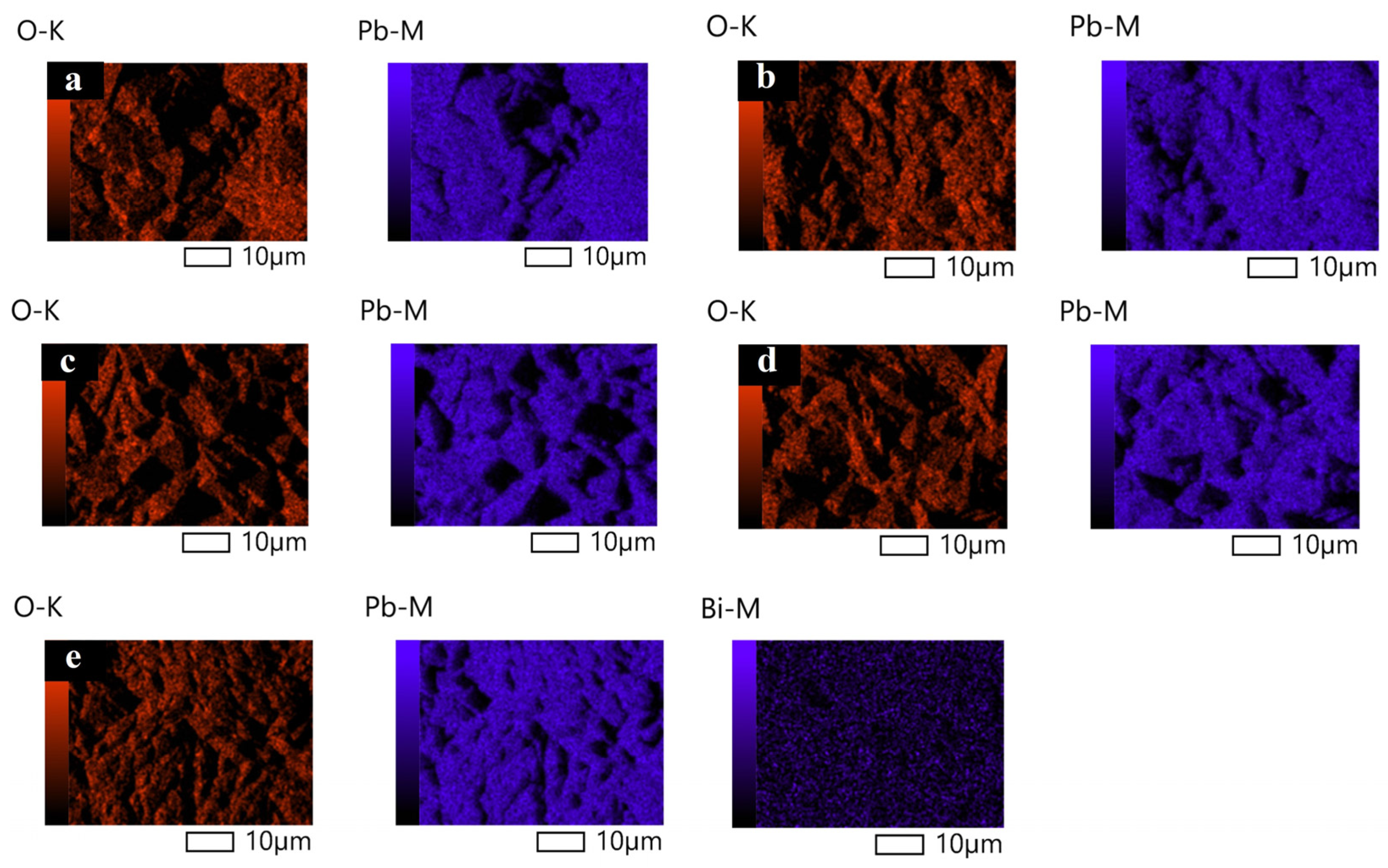
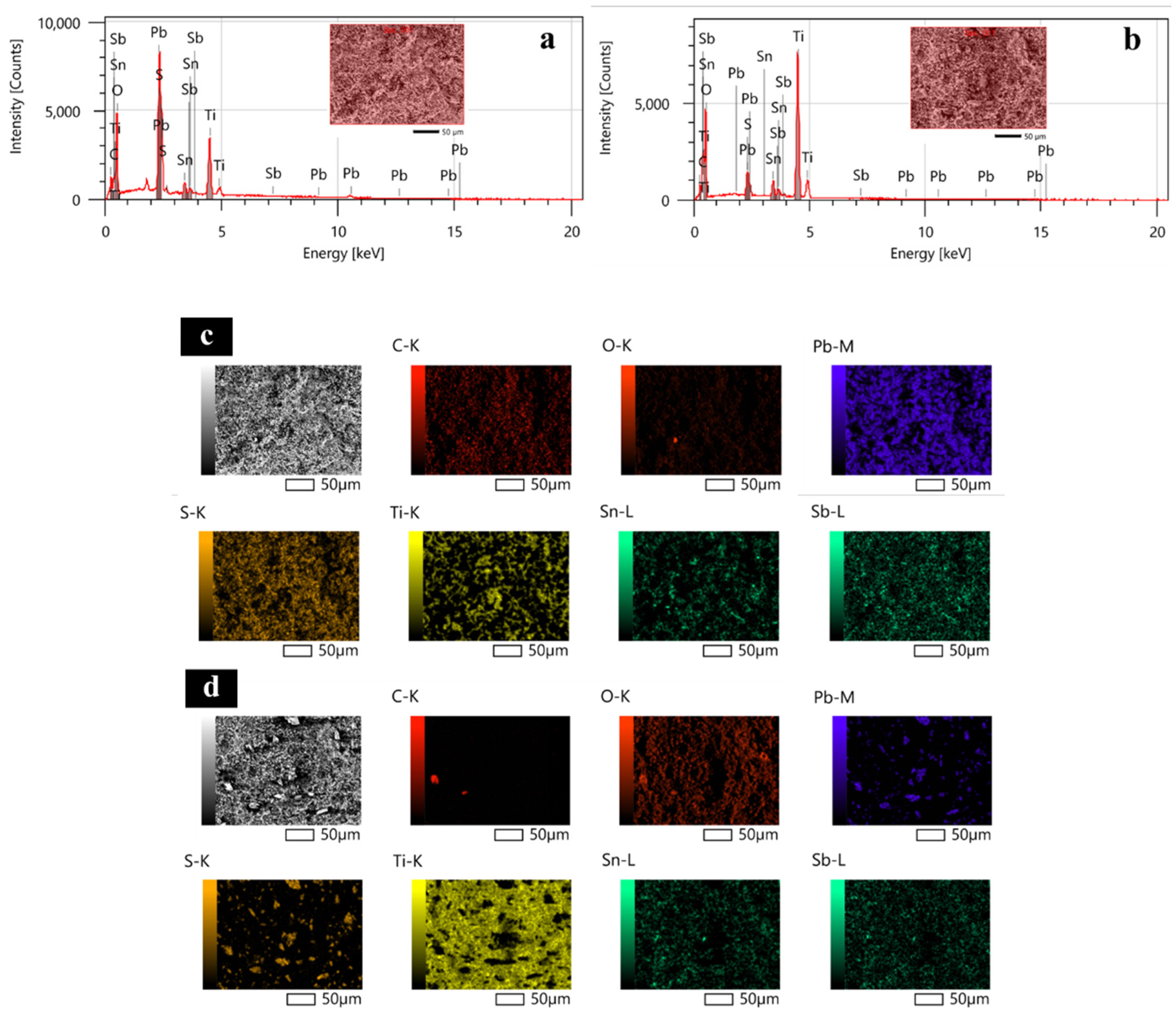
2.1. Surface Morphology and Crystal Structure
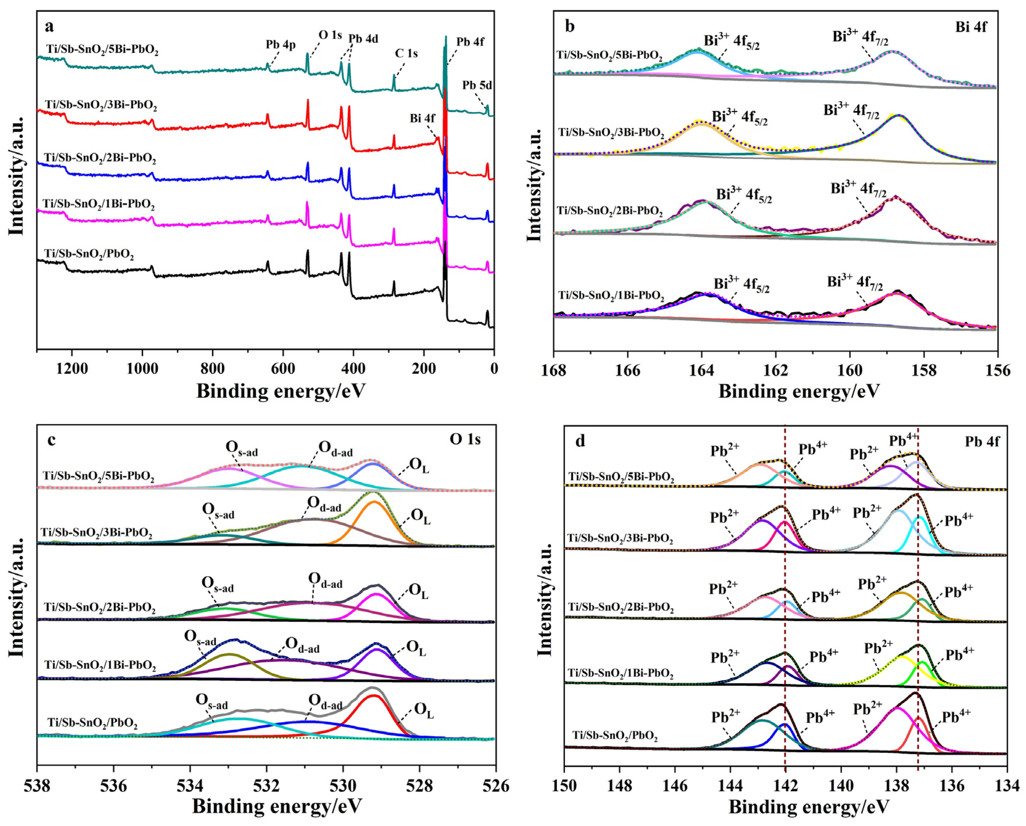
The surface morphologies of Ti/Sb-SnO2/Bi-PbO2 electrodes prepared at different Bi3+ concentrations are shown in Figure 2. It can be seen that the addition of Bi3+ into a PbO2 coating significantly affects the coating morphology. The film becomes denser and the particles become smaller with the introduction of Bi3+. We suggest that the doping of Bi3+ into the PbO2 coating could improve the coating structure effectively. This can be attributed to the formation of heterogeneous nuclei of bismuth oxide, which increases the number of crystal nuclei and hinders the growth of particles during the crystallization of the coating [36]. The particles on the electrode surface exhibit the smallest size when the Bi(NO3)3 concentration is 2 mmol·L−1. However, a further increase in Bi(NO3)3 concentration is not beneficial for the decrease in the size of the particles. The corresponding EDS mapping images of the Bi, O, and Pb elements are shown in Figure 3. We found that the Bi element is not detected in Ti/Sb-SnO2/PbO2, Ti/Sb-SnO2/1Bi-PbO2, Ti/Sb-SnO2/2Bi-PbO2, or Ti/Sb-SnO2/3Bi-PbO2, due to the detection limits of the instrument. However, the Bi element is evenly distributed on the Ti/Sb-SnO2/5Bi-PbO2 electrode surface.
Figure 4 shows the XRD patterns of the as-prepared electrodes with a variation Bi3+concentration. As depicted in Figure 4, the diffraction peaks observed at 2θ = 25.4°, 32.0°, 36.2°, 52.1°, 58.9°, 62.5°, 74.4° were assigned to the (110), (101), (200), (220), (310), (301), and (321) planes of β-PbO2 (JCPDS#41-1492). The diffraction peaks observed at 2θ = 28.6° were assigned to the (111) plane of α-PbO2 (JCPDS#45-1416). It was found that all the electrodes exhibited reflections of β-PbO2 and α-PbO2. No peaks corresponding to bismuth oxide were detected in the XRD pattern of Ti/Sb-SnO2/xBi-PbO2, indicating that the doping amount of bismuth is small and lower than the detective limit of XRD. It should be noted that the crystalline of α-PbO2 and the main plane of β-PbO2 varied with the concentration of Bi3+ doping. The main planes of Ti/Sb-SnO2/PbO2 were (110) and (220). After doping with a low-concentration Bi(NO3)3 (≤2 mmol·L−1), the diffraction peaks of crystal planes (101) and (301) were enhanced, indicating that the directions of crystal planes (101) and (301) were preferentially selected. However, Bi(NO3)3 content which was too high was not favorable for the growth of crystal planes (101) and (301). When the concentration of Bi(NO3)3 was 5 mmol·L−1, the main plane of Ti/Sb-SnO2/5Bi-PbO2 was (220). These results imply that the doping concentration of Bi(NO3)3 affects the selective growth of β-PbO2 crystal planes.

2.2. XPS Analysis

An XPS measurement is performed to further analyze the chemical states of the elements supported on the as-synthesized electrodes. Figure 5a reveals the survey spectrum of the as-prepared electrodes, which exhibit Pb, O, and C elemental signals. Moreover, Bi3+ elemental peaks can be observed for Ti/Sb-SnO2/xBi-PbO2 (x = 1, 2, 3, 5), suggesting that Bi ions are successfully doped in the PbO2 coating. Figure 5b displays the 4f core-level spectra recorded for Bi. The peaks at 158.7 and 163.8 eV correspond to Bi 4f7/2 and Bi 4f5/2, respectively, which confirms the presence of the Bi3+ species. Figure 5c shows the O 1s core level of the as-prepared electrodes, which can be deconvoluted into three characteristic peaks: lattice oxygen species (~529.2 eV for OL), surface oxygen vacancies and adsorbed oxygen (530.5–531.7 eV for Od-ad), and surface adsorbed molecular water (~532.9 eV for Os-ad), as listed in Table 1. It should be noted that the formation of surface oxygen vacancies is closely related to the highly oxidative oxygen species and is active for catalyzing OER [37]. From Table 1, it can be found that the proportions of Od-ad present on the electrode surface first increase with the Bi3+ doping content and then decrease with a further increase of the Bi3+ doping content. The maximum proportion of Od-ad is obtained when the concentration of Bi(NO3)3 is 2 mmol·L−1, indicating the best OER activity.
To elucidate the impact of doping on PbO2 electrodeposition, the Pb 4f spectrum was performed, as shown in Figure 5d. In the Ti/Sb-SnO2/PbO2 electrode, peaks of 142.01 eV and 137.20 eV correspond to the Pb4+, while peaks of 142.82 eV and 137.96 eV correspond to Pb2+, as shown in Table 2. The simultaneous presence of Pb4+ and Pb2+ in the electrode indicates the formation of non-stoichiometric PbO2 during the electrodeposition. After doping with Bi3+, the binding-energy peak of Pb4+ shifted, suggesting a strong interaction between Bi3+ and Pb [38]. This converts some PbO2 into a lower-valence compound, promoting the proportion of non-stoichiometric PbO2, thus improving the electrode conductivity.

2.3. Hydrophilicity Analysis

The hydrophilicity of the surfaces has been shown to promote the charge-transfer rate between the electrolytes and the electrodes, enhancing the oxygen evolution reaction activity. Therefore, the contact angle of the as-synthesized electrodes was measured to evaluate the surface wettability. As shown in Figure 6, the contact angles (θ) in Ti/Sb-SnO2/PbO2, Ti/Sb-SnO2/1Bi-PbO2, Ti/Sb-SnO2/2Bi-PbO2, Ti/Sb-SnO2/3Bi-PbO2, and Ti/Sb-SnO2/5Bi-PbO2 were 60.3°, 29.1°, 21.6°, 27.1°, and 27.7°, respectively. It can be found that much smaller θ are observed for the Ti/Sb-SnO2/xBi-PbO2 electrode compared to pure Ti/Sb-SnO2/PbO2 (60.3°), indicating the enhanced compatibility and affinity of the electrode for Bi3+ doping, which in turn leads to enhancement of their catalytic activity in the OER. When the concentration of Bi(NO3)3 further increases, the contact angles of Ti/Sb-SnO2/3Bi-PbO2 and Ti/Sb-SnO2/5Bi-PbO2 are slightly higher than that of Ti/Sb-SnO2/2Bi-PbO2, which may be ascribed to the change of crystal planes for the electrode.

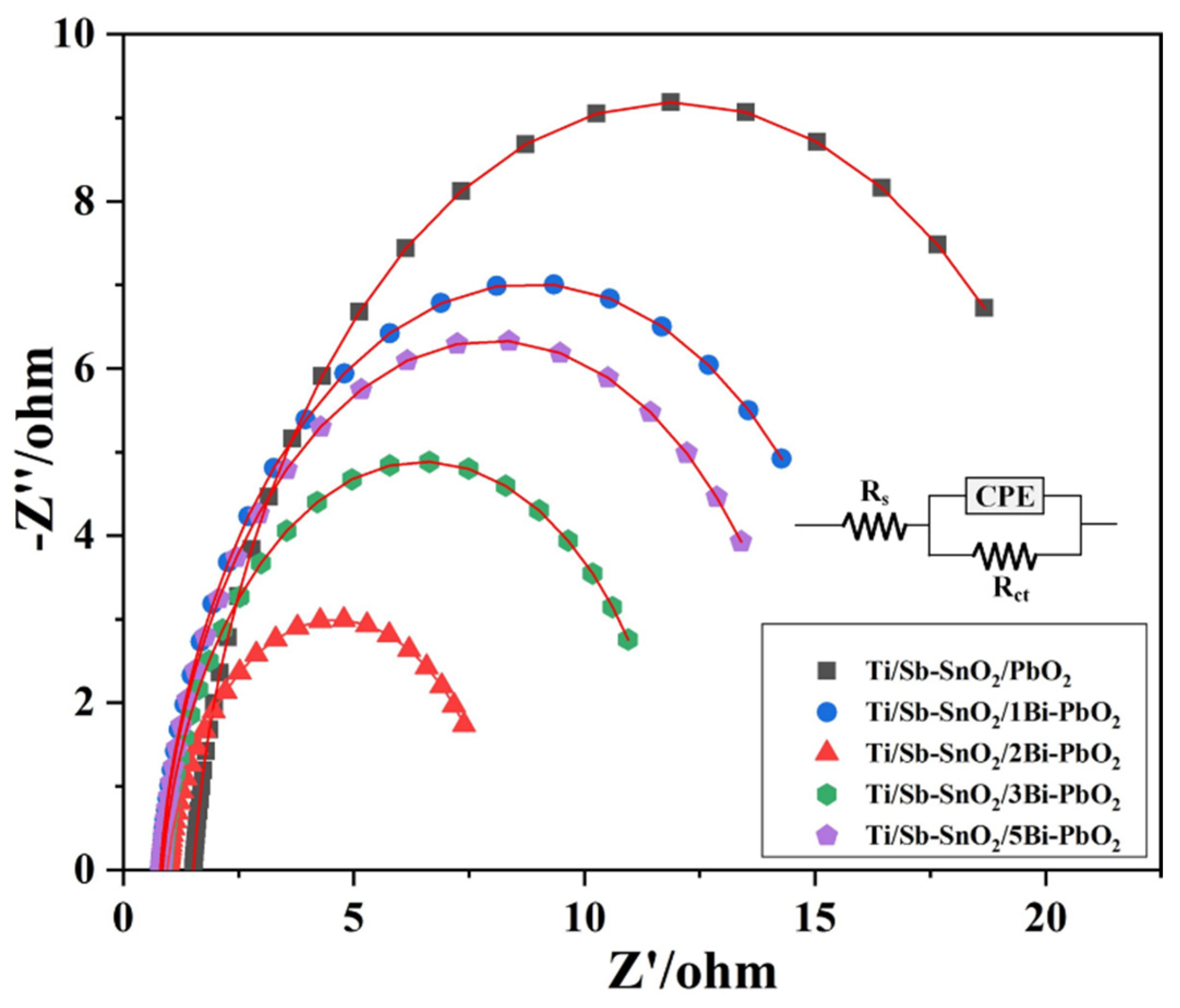
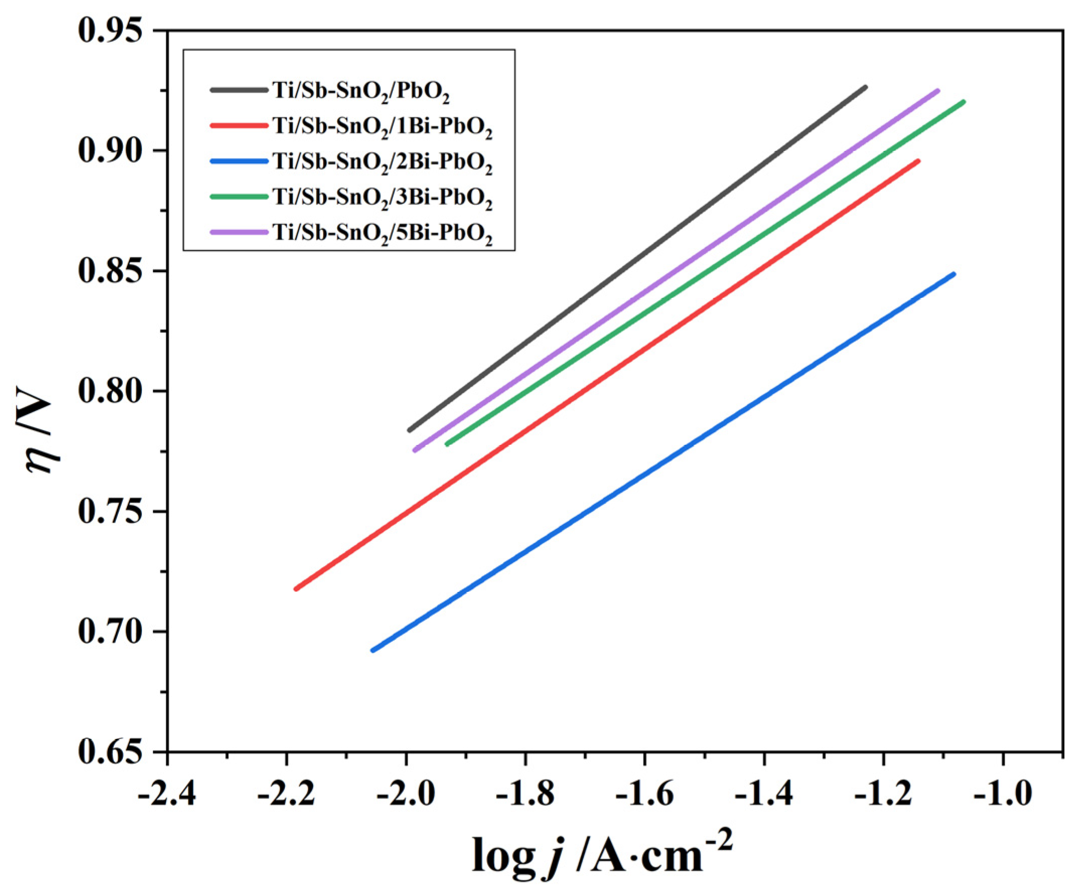
2.4. Electrochemical Property

An LSV test was performed to obtain the oxygen evolution potentials (OEP) of the as-prepared electrodes, as displayed in Figure 7. The results show that the OEP of the electrode decreases with the addition of Bi(NO3)3. The onset potentials for OEP on Ti/Sb-SnO2/PbO2, Ti/Sb-SnO2/1Bi-PbO2, Ti/Sb-SnO2/2Bi-PbO2, Ti/Sb-SnO2/3Bi-PbO2, and Ti/Sb-SnO2/5Bi-PbO2 are 1.99 V, 1.84 V, 1.80 V, 1.87 V, and 1.93 V (vs. Ag/AgCl), respectively. This implies that the introduction of Bi3+ provides more active sites for the oxygen evolution reaction, and that the electrocatalytic activity gradually increased. Furthermore, as shown in Figure 7, the potential of the Ti/Sb-SnO2/2Bi-PbO2 electrode is found to be 89 mV lower than that of the Ti/Sb-SnO2/PbO2 electrode (500 A/m2), indicating that the addition of Bi3+ can effectively improve the electrocatalytic activity of the PbO2 electrode. However, when the concentration was greater than 2 mmol·L−1, there was little difference in potential, and the increase of Bi3+ resulted in the excessive increase of PbO2 crystal grain. This may cause a decrease in surface roughness and a decrease in the active regions involved in the reaction.
EIS measurements were conducted to further explain the influence of Bi(NO3)3 on the oxygen evolution capacity of the PbO2 coatings. Figure 8 exhibits the electrochemical impedance of PbO2 electrodes with an applied potential of 1.90 V vs. Ag/AgCl, which corresponds to the oxygen evolution zone. In the equivalent circuits, Rs, Rct, and constant phase angle element (CPE) represent the ohmic resistance, the charge-transfer resistance, and the double-layer capacitance. The Rs include the electrolyte resistance and the active material resistance. Rct reflects the oxygen release reaction activity. The CPE was employed to substitute the capacitance when n is between 0.9 and 1. The simulation data for each parameter are shown in Table 3. The Rct value of the Ti/Sb-SnO2/2Bi-PbO2 electrode is 7.30 ohm, which is lower than those of the other electrodes. The Ti/Sb-SnO2/PbO2 electrode exhibits the largest Rct value of 20.80 ohm. Furthermore, the Rct value gradually reduced with the addition of Bi(NO3)3. The minimum value was obtained when the Bi(NO3)3 concentration was 2 mmol·L−1. On the contrary, the Rct value increased slightly when the Bi(NO3)3 concentration was further increased, indicating that the modification of Bi3+ could significantly increase the catalytic activity of the coating, and that the optimum Bi(NO3)3 concentration is 2 mmol·L−1. It can be inferred that high oxygen evolution activity and low Rct are in favor of the catalytic activity. Earlier research has observed that oxygen evolution activity depends on the active site of the PbO2 coating, and that large active sites imply good reactivity [39].
The oxygen evolution activity can be determined by comparing the oxygen evolution overpotentials. Figure 9 displays the Tafel curve of the as-prepared electrodes. The oxygen evolution overpotential (η) was employed to investigate the oxygen evolution overpotential (η) of the electrode material and it was obtained according to Formula (2) [40]:
η = E + 0.224 − 1.241 − iRs
where E represents the potential for the reference electrode (Ag/AgCl), measured by the anodic polarization curve; 1.241 V is the standard potential in the measurement system (50 g·L−1 Zn2+ + 150 g·L−1 H2SO4); 0.224V is the potential of the Ag/AgCl relative to the standard hydrogen electrode; and Rs is the electrolyte resistance between the reference electrode and the working electrode.
The η and the current density j exhibit a semi-logarithmic relationship, as shown in Formulas (3)–(5):
η = a + blgj;
a = −2.3(RT/βnF)lgJ0;
b = 2.3RT/βnF,
where a and b are Tafel parameters during anodic polarization and j is the measured current density at the relative potential.
The corresponding overpotentials and kinetic parameters for the as-synthesized electrodes are given in Table 4. We found that under the conditions of 500 and 1000 A·m−2, the Ti/Sb-SnO2/2Bi-PbO2 electrode exhibited the lowest η values (0.814 V and 0.862 V), indicating the high probability of oxygen evolution reaction. When the concentration of Bi(NO3)3 increased from 0 to 2 mmol·L−1, the η gradually decreased, and the η began to increase at 3 mmol·L−1. The electrocatalytic performance of the electrode is closely related to the Tafel parameters. Usually, parameter a reflects the cell voltage and the cell voltage decreases with the decreasing value, which means a small energy consumption. Table 4 shows that the values of the electrodes Ti/Sb-SnO2/PbO2 and Ti/Sb-SnO2/2Bi-PbO2 are 1.141 V and 1.023 V, respectively. The variation of a value and η follows the same tendency. Moreover, the b value represents the overpotential of the material. The smaller b value denotes high catalytic activity. The electrode fabricated at 2 mmol·L−1 Bi(NO3)3 exhibited the lowest b value, indicating the highest catalytic activity for an oxygen evolution reaction. This consequence is in accord with the EIS results.
The amount of voltammetric charge (q*) is related to the actual surface area and number of active sites, which can reflect the electrochemical activity of the electrode [41]. It is found that the q* depends on the potential scan rate (ν). Therefore, q* can be obtained by integrating the CV curve. Figure 10 displays the CV curve of the as-prepared electrodes under various potential scan rates. According to the literature, total voltammetric charge (qT*), outer voltammetric charge (qo*), and inner voltammetric charge (qi*) are calculated by the Equations (6)–(8), respectively.
q* = qo* + k1ν−1/2;
q*−1 = qT*−1 + k2ν1/2;
qT* = qo* + qi*,
where k1 and k2 are constants; ν is the scan rate. It is reported that qT* and qi* are related to the entire electroactive surface and to less accessible electroactive sites, respectively. The electrochemical porosity can be obtained by computing qi*/qT*. Figure 11a shows that q* is linearly related to ν−1/2, and qo* can be obtained from the extrapolation to ν−1/2 = 0. Moreover, q*−1 is also linearly related to ν1/2, and extrapolation of these straight lines to ν1/2 = 0 gives qT*, as shown in Figure 11b.
Table 5 summarizes the total, outer, and inner charges obtained for the as-prepared electrodes. The qT* of Ti/Sb-SnO2/PbO2, Ti/Sb-SnO2/1Bi-PbO2, Ti/Sb-SnO2/2Bi-PbO2, Ti/Sb-SnO2/3Bi-PbO2, and Ti/Sb-SnO2/5Bi-PbO2 is 4.44 C·cm−2, 7.25 C·cm−2, 21.20 C·cm−2, 11.49 C·cm−2, and 11.01 C·cm−2, respectively. It can be seen that the doping of Bi3+ could greatly improve the electroactive surface of the electrodes. The electrode prepared at 2 mmol·L−1 Bi(NO3)3 exhibited the highest qT*, suggesting a higher electroactive surface. However, excessive doping resulted in a decrease in qT*, which is not beneficial for the increase in the electroactive surface. Moreover, the ratio of qi*/qT* for Ti/Sb-SnO2/2Bi-PbO2 electrodes is higher than the other electrodes, which is in favor of an increase in the active site. This result is consistent with the Tafel tendency.

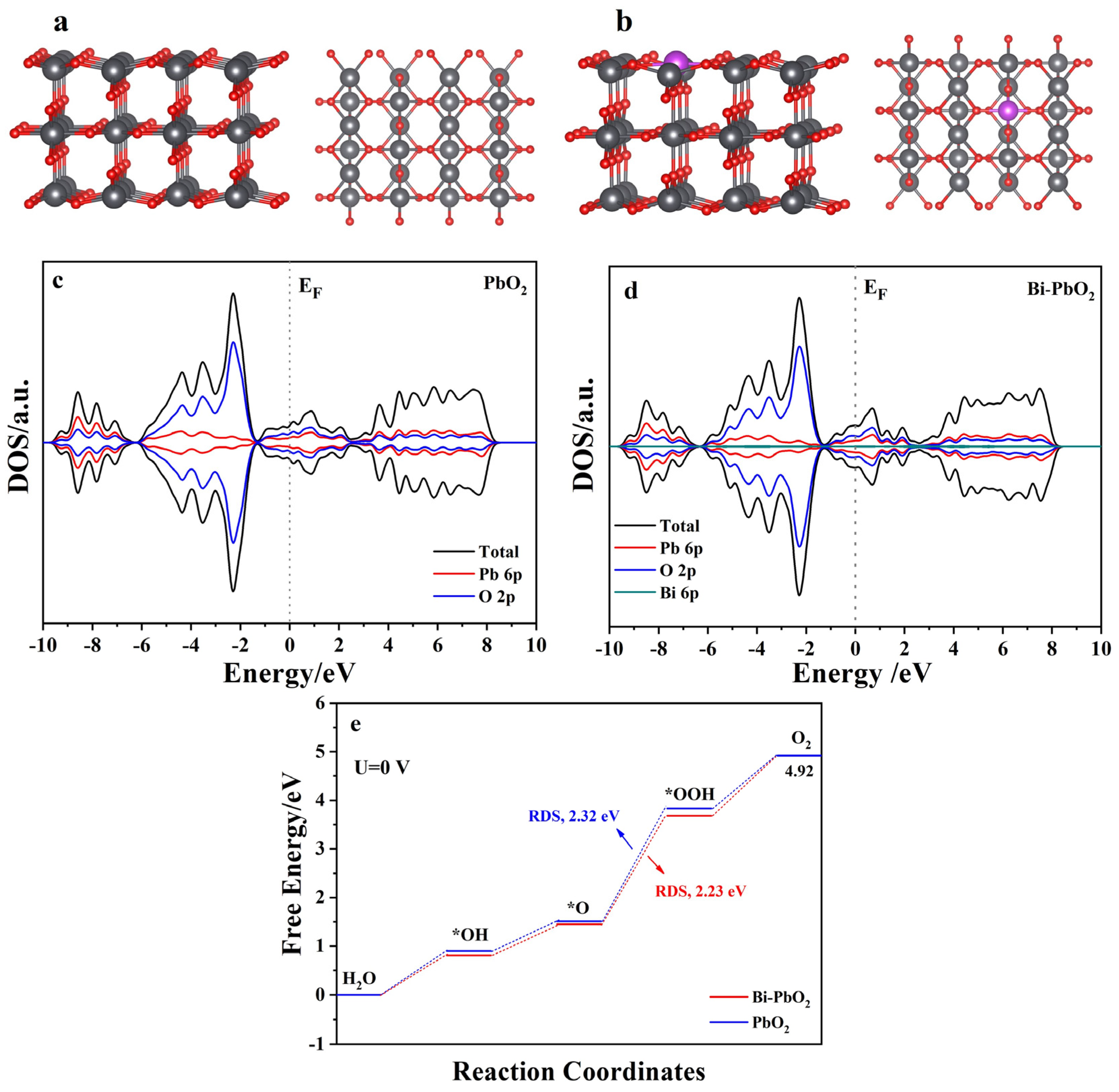
2.5. DFT Calculations

To verify the effect of Bi3+ doping on PbO2, the Density of State (DOS) and the OER activity of the Bi atom were studied using DFT calculations (Figure 12). Figure 12a,b displays the Schematic diagram of the structures. Figure 12c,d shows the DOS of the PbO2 and Bi-PbO2 electrodes. We observe that Bi doping could slightly improve the value of the DOS at the Fermi level. Thus, the introduction of Bi can improve electrode conductivity. The Gibbs free energies of the PbO2 and Bi-PbO2 at each step of their OER reactions are also calculated (Figure 12e). According to the literature [42,43,44], OER is a four-electron step process. Oxygen intermediates include *OH, *O, and *OOH. The largest Gibbs free energy is usually considered as the rate-determining step (RDS), which determines the electrode OER electrocatalytic activity. As shown in Figure 12e, the conversion of *O to *OOH is the RDS of the PbO2 and Bi-PbO2. In the RDS procedure, the energy barrier of PbO2 and Bi-PbO2 is 2.32 eV and 2.23 eV, respectively. Therefore, the electrocatalytic activity of the Bi-PbO2 electrodes is higher than that of the PbO2 electrode. The difference in energy barrier can be ascribed to the introduction of the Bi atom and the enhanced catalytic sites. Combined with theoretical calculations, the Bi doping leads to a decrease in the OER reaction barrier and an increase in the specific surface area of the electrode, which further improves the activity of the catalytic layer. These findings are consistent with the experimental results.

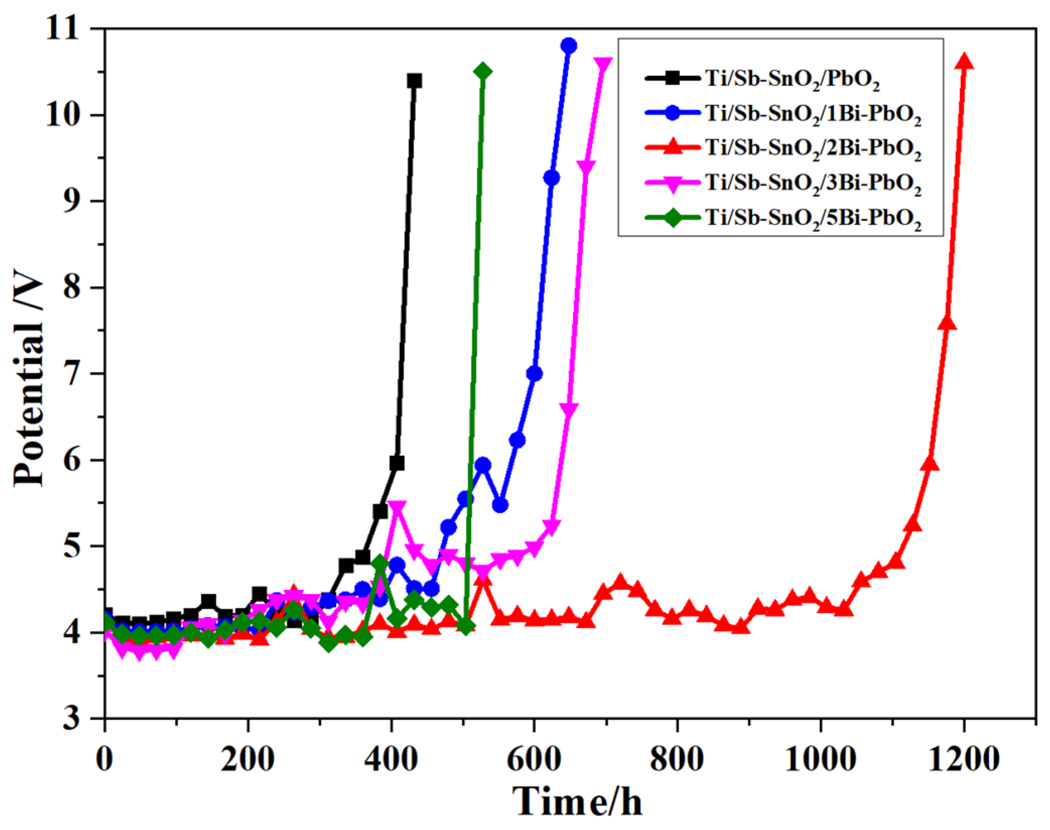
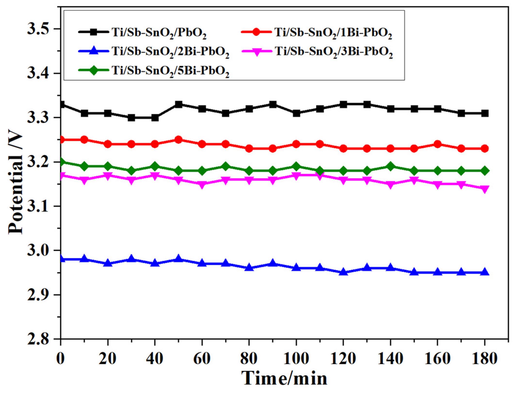
2.6. Electrochemical Stability Test

The accelerated life tests were carried out to evaluate the electrodes’ stability. Figure 13 displays the time course of cell potential in the accelerated life measurement for the as-prepared electrodes. It is observed that the Ti/Sb-SnO2/2Bi-PbO2 electrode exhibits the longest lifetime of 1196 h, which is 2.79 times that of the Ti/Sb-SnO2/PbO2 electrode (428 h). The lifetime of Ti/Sb-SnO2/2Bi-PbO2 electrodes is longer than those of the other electrodes. This can be attributed to the growth of the PbO2 crystal grain, which reduces the gap between the grain boundaries, making the electrode surface denser. The SEM results show that the PbO2 particle size becomes small after Bi3+ doping. The decrease in the PbO2 particle size could reduce the defect density of the electrode surface and make a compact and fine surface layer. The compact electrode surface could not only baffle the penetration of the electrolyte through cracks and pores but also prevent an increase in pressure inside the electrode, caused by the internal oxygen evolution. The lifetime of the Ti/Sb-SnO2/3Bi-PbO2 electrode is smaller than that of the Ti/Sb-SnO2/2Bi-PbO2 electrode. This is probably because the nucleation rate is larger than the growth rate of the grain, thereby increasing grain addition. Moreover, the internal stress of the crystal grain is increased, and the surface is cracked. Therefore, the corrosion resistance of the electrode is reduced. The SEM of the as-prepared deactivated electrodes was measured to study the deactivated behavior, as shown in Figure 14. It is observed that the coating of all deactivated electrodes disappeared, and some granular agglomeration was on the electrode. The EDS and EDS-mapping results of the undoped Ti/Sb-SnO2/PbO2 electrode and the Ti/Sb-SnO2/2Bi-PbO2 electrode are displayed in Figure 15. It can be seen that Ti, Sn, and Sb elements were detected in both of the deactivated electrodes, indicating that the coating fell off from the electrode surface and that the Sb-SnO2 intermediate layer and the Ti substrate were exposed. Moreover, Pb, S, and O elements were also measured. This can be ascribed to the transformation of PbO2 to PbSO4 during the long-time electrolysis process. From these results, we can speculate that the deactivation of the electrode is due to the detachment of the active layer.

2.7. Simulated Zinc Electrowinning Experiment

The simulated zinc electrowinning experiment was carried out to study the voltage change of the electrode. Figure 16 shows the cell voltage of the as-prepared electrodes during the 3 h zinc electrowinning process. The cell potential was calculated using the following equation:
U = (E1 − E2) + IR
where E1 − E2 is the electrode polarization potential, including the theoretical decomposition voltage and overpotential of ZnSO4. R is the total resistance, including the electrode resistance, electrolyte resistance, and contact resistance. The average cell potentials of Ti/Sb-SnO2/PbO2, Ti/Sb-SnO2/1Bi-PbO2, Ti/Sb-SnO2/2Bi-PbO2, Ti/Sb-SnO2/3Bi-PbO2, and Ti/Sb-SnO2/5Bi-PbO2 are 3.32 V, 3.24 V, 2.96 V, 3.16 V, and 3.18 V, respectively. It can be seen that the doping of Bi3+ reduces the cell voltage of the electrodes. From the Tafel curve, it can be found that the b value decreases with the introduction of Bi3+, indicating a small overpotential of the electrode. According to Equation (9), the cell voltage decreases with the decrease in the polarization potential. Moreover, it should be noted that the polarization potential has a positive relationship with the overpotential. Therefore, the decrease in overpotential results in a decrease in voltage drop. Commonly, the small cell potential is favorable for the reduction in energy consumption. The smallest cell voltage was obtained by the Ti/Sb-SnO2/2Bi-PbO2 electrode, suggesting less energy consumption during zinc electrowinning.

3. Experimental Details

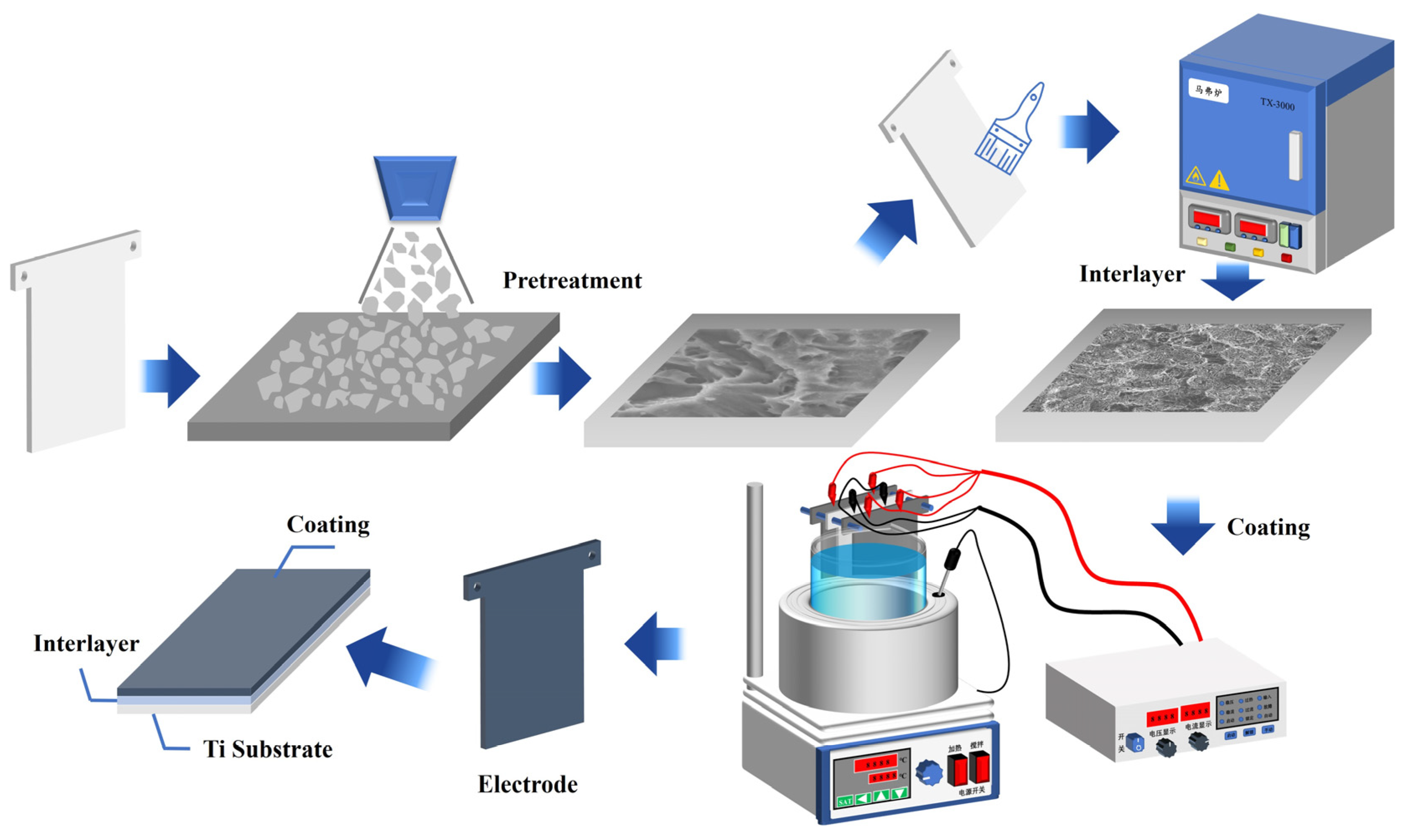
3.1. Pretreatment of Ti Sheet

The Ti foil (TA1), with a 1.5 mm thickness, was cut into pieces with a dimension of 80 mm × 100 mm before the experiments. The surface of the Ti sheet was subjected to pre-treatment to obtain a gray surface with uniform roughness. The pre-treatment contained degreasing, polishing, and etching for 2 h in boiling oxalic acid. Finally, the specimens were washed with distilled water.

3.2. Preparation of Sb-SnO2 Interlayer

The sol-gel technique was employed to deposit the Sb-SnO2 interlayer to prevent the passivation of the Ti substrate. The citric acid (CA) was dissolved in ethylene glycol (EG) to form citric acid ester, which was then added to SnCl4 and SbCl3 to obtain sol-gel precursor solutions. The molar ratio of Sn: Sb was 10:1 and the molar ratio of CA: EG was 1:4. The precursor solutions were brushed on the acid-etched Ti sheet and then placed in an oven at 130 °C and annealed at 500 °C. This procedure was repeated several times.

3.3. Synthesis of Bi3+ Doped Ti/Sb-SnO2/PbO2 Electrode

Bi3+ doped Ti/Sb-SnO2/PbO2 electrodes were prepared using an anodic electrodeposition approach with a Ti sheet as the cathode. The deposition solutions contained Pb(NO3)2, Cu(NO3)2, HNO3, some additives, and 0–5 mmol·L−1 Bi(NO3)3. The current density was controlled at 200 A·m−2 for 2 h and the bath temperature was 60 °C. Magnetic stirring was employed to enhance the electrolytic diffusion property. The as-prepared electrodes were rinsed thoroughly with deionized water and were denoted as Ti/Sb-SnO2/xBi-PbO2, where x (x = 1, 2, 3, 5) presents the Bi3+ concentration. In addition, the blank sample was also prepared and was marked as Ti/Sb-SnO2/PbO2.

3.4. Characterization and Electrochemical Measurements

The surface morphology and composition of the as-prepared electrodes were characterized using scanning electron microscopy (SEM, JSM-IT200, JEOL, Tokyo, Japan), and the microscope was equipped with an energy-dispersive X-ray spectroscopy (EDS, JEOL, Tokyo, Japan) detector. The crystal pattern of the electrodes was detected by an X’pert PRO MRD diffractometer (XRD, D8 Advance, Bruker, Germany). The chemical states of Pb, O, and Bi in the as-prepared electrodes were determined using X-ray photoelectron spectroscopy (XPS, ESCALAB 250Xi, ThermoFisher, Waltham, MA, USA) on an Ultra DLD Electron Spectrometer (Al Ka radiation; hν = 1486.71 eV). The binding energy of each spectrum was calibrated with C1s (284.8 eV) and was fitted using commercial software (Thermo Avantage 5.9931). Powereach JC2000D was used to measure the contact angle (θ) of the electrode surface. To avoid the effect of the droplet’s gravity on the contact angle, all contact angles were tested 10 s after the droplets were dropped onto the facet. The experiment was conducted at room temperature (25 °C).
An electrochemical workstation (Corrtest CS2350) was adopted to conduct electrochemical research using a traditional three-electrode system. The working electrode was the as-prepared electrode connected to a reference electrode (SCE). The Pt sheet served as the counter electrode. The simulated zinc electrowinning electrolyte was composed of 50 g·L−1 Zn2+ and 150 g·L−1 H2SO4. The linear sweep voltammetry (LSV) characterization was measured at the scan rate of 10 mV·s−1. Cyclic voltammetry (CV) was performed at the scan rate between 10 and 100 mV·s−1. The voltammetric charge (q*) was evaluated by integrating cyclic voltammograms. EIS experiments were carried out at 1.9 V in the frequency range of 100 kHz–0.1 Hz with an amplitude of 5 mV. The potential values in this work are all quoted with respect to Ag/AgCl. Accelerated life tests were carried out to research the stability and lifetime of the as-prepared electrodes in 15% H2SO4 aqueous solutions with a current density of 10,000 A·m−2. In this procedure, the experiment is supposed to be finished when the cell voltage is higher than 10 V. Moreover, to study the anodic performance and durability of the composited electrodes, galvanostatic polarization was tested under the simulated zinc electrowinning condition at a current density of 450 A·m−2.

3.5. Theoretical Calculation

First-principle calculations were conducted on the Vienna Ab initio Simulation Package (VASP (6.X.X.)) [45]. The exchange-correlation influences are described by the Perdew-Burke-Ernzerhof (PBE) functional within the generalized gradient approximation (GGA) method [46]. The core-valence interactions were accounted for using the projected augmented wave (PAW) method [47]. The simulation model was built based on Visualization for electronic and structural analysis (VESTA (3.5.8)) software. The simulation model for Bi-PbO2 was built by uniformly doping Bi atoms into PbO2 (110) fragments. The energy cutoff for plane wave expansions was set to 480 eV, and the 3 × 3 × 1 Monkhorst-Pack grid k-points were selected to sample the Brillouin zone integration. The vacuum space was adopted 15 Å above the surfaces to avoid periodic interactions. The structural optimization was completed for energy and force convergence set at 1.0 × 10⁻⁴ eV and 0.02 eV Å−1, respectively.
The Gibbs free energy change (ΔG) of each step was calculated using Formula (1)
∆G = ∆E + ∆ZPE − T∆S
where ΔE is the electronic energy difference directly obtained from DFT calculations; ΔZPE is the zero point energy difference; T is the room temperature (298.15 K); and ΔS is the entropy change.

4. Conclusions

In this study, we studied the role of Bi(NO3)3 doping in enhancing the electrochemical performance of Ti/Sb-SnO2/PbO2 electrodes in zinc electrowinning. The XPS measurement confirms that Bi3+ is successfully doped into the electrode. The addition of Bi(NO3)3 could refine the surface grain, change crystal structure, improve the hydrophilicity, and enhance the electrocatalytic activity of the Ti/Sb-SnO2/PbO2 electrode. We found that the Bi(NO3)3 content has a significant influence on the coating morphology, the crystal orientation, the surface hydrophilicity, the oxygen evolution reaction kinetics, the charge-transfer efficiency, the stability, and the reactivity. The hydrophilicity, the OEP, and the Rct exhibit a declining trend when there is an increase in the Bi(NO3)3 concentration. The optimum electrocatalytic activity of the Ti/Sb-SnO2/Bi-PbO2 electrode is achieved when the concentration of Bi(NO3)3 is 2 mmol·L−1. The Ti/Sb-SnO2/2Bi-PbO2 electrode illustrates the largest qT* of 21.20 C·cm−2 and the lowest overpotential of 0.814V (500 A·m−2), suggesting that it has the more active site and the higher oxygen evolution activity. Our DFT calculations demonstrate that the introduction of Bi3+ leads to a decrease in the OER reaction barrier and an increase in the DOS of the electrode, which further enhances the catalytic activity and conductivity of the electrode. This theoretical calculation is consistent with the experimental results. Furthermore, the accelerated life measurement indicates that the introduction of Bi3+ can enhance the stability of the electrode, and that the Ti/Sb-SnO2/2Bi-PbO2 electrode possesses the highest accelerated lifetime of 1196 h, which is 2.79 times that of the undoped electrode. The reason for the failure of the electrode is that the active coating gradually detaches from the electrode surface as the electrolysis time increases, until the active layer disappears completely. Furthermore, compared with the undoped electrode, the cell voltage of the Ti/Sb-SnO2/2Bi-PbO2 electrode is reduced, indicating less energy consumption. In summary, the proper doping of Bi3+ is beneficial for improving the electrocatalytic activity of the Ti/Sb-SnO2/PbO2 electrode. These attractive results show that the potential future applications of this electrode material should be strongly anticipated in zinc electrowinning.

Author Contributions

Conceptualization, J.W. and Z.W.; Methodology, J.W. and K.L.; Software, J.W., S.X. (Shangyuan Xu) and K.L.; Validation, Y.W.; Formal analysis, S.X. (Shuangwen Xu) and B.J.; Investigation, X.K., Z.W., S.X. (Shangyuan Xu) and Q.F.; Resources, X.K., Q.F. and B.J.; Data curation, S.X. (Shuangwen Xu); Writing—original draft, J.W.; Writing—review & editing, J.W. and Y.W. All authors have read and agreed to the published version of the manuscript.

Funding

This research was funded by the National Natural Science Foundation of China (Grant No. 21878242); Xi’an Talent Program, China (No. 20240020); and the Young Talent Fund of Association for Science and Technology in Shaanxi, China (No. 20230521) and the APC was funded by Xi’an Talent Program, China (No. 20240020).

Institutional Review Board Statement

Not applicable.

Informed Consent Statement

Not applicable.

Data Availability Statement

The data is unavailable due to privacy.

Conflicts of Interest

Authors J.W., X.K., S.X., Z.W., S.X., K.L., Q.F. and B.J. were employed by the company Xi’an Taijin New Energy & Materials Sci-Tech Co., Ltd. The remaining authors declare that the research was conducted in the absence of any commercial or financial relationships that could be construed as a potential conflict of interest.

References

  1. Ortiz, I.Y.; Santos, A.R.; Costa, A.M.; Mavropoulos, E.; Tanaka, M.N.; Silva, M.H.P.; Camargo, S.S., Jr. In vitro assessment of zinc apatite coatings on titanium surfaces. Ceram. Int. 2016, 42, 15502–15510. [Google Scholar] [CrossRef]
  2. Li, S.; Chen, W.; Huang, X.; Ding, L.; Ren, Y.; Xu, M.; Zhu, J.; Miao, Z.; Liu, H. Enabling wasted A4 papers as a promising carbon source to construct partially graphitic hierarchical porous carbon for high-performance aqueous Zn-ion storage. ACS Appl. Mater. Interfaces 2024, 16, 10126–10137. [Google Scholar] [CrossRef] [PubMed]
  3. Wan, Z.; Wang, H.; Li, J.; Solomon, J.; Zhu, Y.; Carlson, B. Novel measures for spatter prediction in laser welding of thin-gage zinc-coated steel. Int. J. Heat Mass Tran. 2021, 167, 120830. [Google Scholar] [CrossRef]
  4. Rudnik, E. Recovery of zinc from zinc ash by leaching in sulphuric acid and electrowinning. Hydrometallurgy 2019, 188, 256–263. [Google Scholar] [CrossRef]
  5. Xu, X.; Li, D.; Chen, L.; Liu, M.; Liu, C.; Jia, J. Improve the energy efficiency: Effects of additives on longtime zinc electrowinning. Hydrometallurgy 2020, 193, 105326. [Google Scholar] [CrossRef]
  6. Karbasi, M.; Alamdari, E.K.; Dehkordi, E.A. Electrochemical performance of Pb-Co composite anode during Zinc electrowinning. Hydrometallurgy 2019, 183, 51–59. [Google Scholar] [CrossRef]
  7. Skaftun, S.M.; Sunde, S.; Haarberg, G.M.; Seland, F. Deposition and removal of manganese oxide in zinc electrowinning. Electrochim. Acta 2024, 484, 144040. [Google Scholar] [CrossRef]
  8. Xue, Y.; Hao, X.; Liu, X.; Zhang, N. Recovery of zinc and iron from steel mill dust-an overview of available technologies. Materials 2022, 15, 4127. [Google Scholar] [CrossRef] [PubMed]
  9. Valdrez, I.V.; Almeida, M.F.; Dias, J.M. Direct recovery of Zn from wasted alkaline batteries through selective anode’s separation. J. Environ. Manage. 2022, 321, 115979. [Google Scholar] [CrossRef]
  10. Kim, H.K.; Jang, H.; Jin, X.; Kim, M.G.; Hwang, S.J. A crucial role of enhanced Volmer-Tafel mechanism in improving the electrocatalytic activity via synergetic optimization of host, interlayer, and surface features of 2D nanosheets. Appl. Catal. B Environ. 2022, 312, 121391. [Google Scholar] [CrossRef]
  11. Abedini, A.; Valmoozi, A.A.E.; Afghahi, S.S.S. Anodized graphite as an advanced substrate for electrodeposition of PbO2. Mater. Today Commun. 2022, 31, 103464. [Google Scholar] [CrossRef]
  12. Sangeetha, V.; Sivakumar, V.; Sudha, A.; Kannan, K. Electrochemical degradation of sago wastewater using Ti/PbO2 electrode: Optimisation using response surface methodology. Int. J. Electrochem. Sci. 2014, 10, 1506–1516. [Google Scholar] [CrossRef]
  13. Tao, Y.; Luo, K.; Chang, L.; Chen, B.; Huang, H.; He, Y.; Guo, Z. The influence of rare earth La on properties of lead-based alloy anode for zinc electrowinning. J. Solid State Electr. 2022, 26, 2555–2564. [Google Scholar] [CrossRef]
  14. Li, H.; Yuan, T.; Li, R.; Wang, W.; Zheng, D.; Yuan, J. Electrochemical properties of powder-pressed Pb-Ag-PbO2 anodes. Trans. Nonferr. Met. Soc. 2019, 29, 2422–2429. [Google Scholar] [CrossRef]
  15. Ye, W.; Xu, F.; Jiang, L.; Duan, N.; Li, J.; Zhang, F.; Zhang, G.; Chen, L. A novel functional lead-based anode for efficient lead dissolution inhibition and slime generation reduction in zinc electrowinning. J. Clean. Prod. 2021, 284, 124767. [Google Scholar] [CrossRef]
  16. Zhou, Y.; Chen, J.; Jiang, L. Industrial tests of composite porous Pb-Ag anode in zinc electrowinning plant. Ionics 2023, 29, 377–385. [Google Scholar] [CrossRef]
  17. Wang, W.; Yuan, T.; Li, R.; Zhu, X.; Li, H.; Lin, W.; Li, L.; Zheng, D. Electrochemical corrosion behaviors of Pb-Ag anodes by electric current pulse assisted casting. J. Electroanal. Chem. 2019, 847, 113250. [Google Scholar] [CrossRef]
  18. Wang, S.; Zhou, X.; Yuan, M.; Long, B.; Wang, H.; Tang, J.; Yang, J. Electrochemical properties of Pb-0.6wt% Ag powder-pressed alloy in sulfuric acid electrolyte containing Cl/Mn2+ ions. Hydrometallurgy 2018, 177, 218–226. [Google Scholar] [CrossRef]
  19. Wang, X.; Wang, J.; Jiang, W.; Chen, C.; Xu, R. Facile synthesis MnCo2O4 modifying PbO2 composite electrode with enhanced OER electrocatalytic activity for zinc electrowinning. Sep. Purif. Technol. 2021, 272, 118916. [Google Scholar] [CrossRef]
  20. Tang, C.; Lu, Y.; Wang, F.; Niu, H.; Xue, J. Influence of a MnO2-WC interlayer on the stability and electrocatalytic activity of titanium-based PbO2 anodes. Electrochim. Acta 2020, 331, 135381. [Google Scholar] [CrossRef]
  21. Zhang, F.; Zuo, J.; Jin, W.; Xu, F.; Jiang, L.; Xi, D.; Wen, Y.; Li, J.; Yu, Z.; Li, Z.; et al. Size effect of γ-MnO2 precoated anode on lead-containing pollutant reduction and its controllable fabrication in industrial-scale for zinc electrowinning. Chemosphere 2022, 287, 132457. [Google Scholar] [CrossRef]
  22. Chen, S.; Li, J.; Liu, L.; He, Q.; Zhou, L.; Yang, T.; Wang, X.; He, P.; Zhang, H.; Jia, B. Fabrication of Co/Pr co-doped Ti/PbO2 anode for efficiently electrocatalytic degradation of β-naphthoxyacetic acid: Efficiency and mechanism. Chemosphere 2020, 256, 127139. [Google Scholar]
  23. Duan, P.; Qian, C.; Wang, X.; Jia, X.; Jiao, L.; Chen, Y. Fabrication and characterization of Ti/polyaniline-Co/PbO2-Co for efficient electrochemical degradation of cephalexin in secondary effluents. Environ. Res. 2022, 214, 113842. [Google Scholar] [CrossRef] [PubMed]
  24. Shao, D.; Li, W.; Wang, Z.; Yang, C.; Xu, H.; Yan, W.; Yang, L.; Wang, G.; Yang, J.; Feng, L.; et al. Variable activity and selectivity for electrochemical oxidation wastewater treatment using a magnetically assembled electrode based on Ti/PbO2 and carbon nanotubes. Sep. Purif. Technol. 2022, 301, 122008. [Google Scholar] [CrossRef]
  25. Zhang, C.; Liu, J.; Chen, B. Effect of Ce(NO3)4 on the electrochemical properties of Ti/PbO2-TiO2-Ce(NO3)4 electrode for zinc electrowinning. Appl. Phys. A-Mater. 2019, 125, 150. [Google Scholar] [CrossRef]
  26. Chen, S.; Chen, B.; Wang, S.; Yan, W.; He, Y.; Guo, Z.; Xu, R. Ag doping to boost the electrochemical performance and corrosion resistance of Ti/Sn-Sb-RuOx/α-PbO2/β-PbO2 electrode in zinc electrowinning. J. Alloys Compd. 2020, 815, 152551. [Google Scholar] [CrossRef]
  27. Zhang, C.; Liu, J.; Chen, B. Effect of CeO2 and graphite powder on the electrochemical performance of Ti/PbO2 anode for zinc electrowinning. Ceram. Int. 2018, 44, 19735–19742. [Google Scholar] [CrossRef]
  28. Dan, Y.; Lu, H.; Liu, X.; Lin, H.; Zhao, J. Ti/PbO2+nano-Co3O4 composite electrode material for electrocatalysis of O2 evolution in alkaline solution. Int. J. Hydrog. Energ. 2011, 36, 1949–1954. [Google Scholar] [CrossRef]
  29. He, S.; Xu, R.; Hu, G.; Chen, B. Electrosynthesis and performance of WC and Co3O4 co-doped α-PbO2 electrodes. RSC Adv. 2016, 6, 3362–3371. [Google Scholar] [CrossRef]
  30. Hakimi, F.; Rashchi, F.; Ghalekhani, M.; Dolati, A.; Astaraei, F.R. Effect of a synthesized pulsed electrodeposited Ti/PbO2-RuO2 nanocomposite on zinc electrowinning. Ind. Eng. Chem. Res. 2021, 60, 11737–11748. [Google Scholar] [CrossRef]
  31. Dolatabadi, M.; Ehrampoush, M.H.; Pournamdari, M.; Ebrahimi, A.A.; Fallahzadeh, H.; Ahmadzadeh, S. Simultaneous electrochemical degradation of pesticides from the aqueous environment using Ti/SnO2-Sb2O3/PbO2/Bi electrode; process modeling and mechanism insight. Chemosphere 2023, 311, 137001. [Google Scholar] [CrossRef]
  32. Figueredo-Sobrinho, F.A.A.; Souza Lucas, F.W.; Fill, T.P.; Rodrigues-Filho, E.; Mascaro, L.H.; Silva Casciano, P.N.; Lima-Neto, P.; Correia, A.N. Insights into electrodegradation mechanism of tebuconazole pesticide on Bi-doped PbO2 electrodes. Electrochim. Acta 2015, 154, 278–286. [Google Scholar] [CrossRef]
  33. Rahmani, A.; Ansari, A.; Seid-mohammadi, A.; Leili, M.; Nematollahi, D.; Shabanloo, A. Bismuth-doped 3D carbon felt/PbO2 electrocatalyst for degradation of diuron herbicide and improvement of pesticide wastewater biodegradability. J. Environ. Chem. Eng. 2023, 11, 109118. [Google Scholar] [CrossRef]
  34. Chang, L.; Zhou, Y.; Duan, X.; Liu, W.; Xu, D. Preparation and characterization of carbon nanotube and Bi co-doped PbO2 electrode. J. Taiwan Inst. Chem. Eng. 2014, 45, 1338–1346. [Google Scholar] [CrossRef]
  35. Gao, G.; Zhang, X.; Wang, P.; Ren, Y.; Meng, X.; Ding, Y.; Zhang, T.; Jiang, W. Electrochemical degradation of doxycycline hydrochloride on Bi/Ce co-doped Ti/PbO2 anodes: Efficiency and mechanism. J. Environ. Chem. Eng. 2022, 10, 108430. [Google Scholar] [CrossRef]
  36. Shmychkova, O.; Luk’yanenko, T.; Yakubenko, A.; Amadelli, R.; Velichenko, A. Electrooxidation of some phenolic compounds at Bi-doped PbO2. Appl. Catal. B-Environ. 2015, 162, 346–351. [Google Scholar] [CrossRef]
  37. Zhu, Y.; Zhou, W.; Yu, J.; Chen, Y.; Liu, M.; Shao, Z. Enhancing electrocatalytic activity of perovskite oxides by tuning cation deficiency for oxygen reduction and evolution reactions. Chem. Mater. 2016, 28, 1691–1697. [Google Scholar] [CrossRef]
  38. Wan, C.; Zhao, L.; Wu, C.; Lin, L.; Liu, X. Bi5+ doping improves the electrochemical properties of Ti/SnO2-Sb/PbO2 electrode and its electrocatalytic performance for phenol. J. Clean. Prod. 2022, 380, 135005. [Google Scholar] [CrossRef]
  39. Yan, Z.; Zhao, Y.; Zhang, Z.; Li, G.; Li, H.; Wang, J.; Feng, Z.; Tang, M.; Yuan, X.; Zhang, R.; et al. A study on the performance of IrO2-Ta2O5 coated anodes with surface treated Ti substrates. Electrochim. Acta 2015, 157, 345–350. [Google Scholar] [CrossRef]
  40. Xu, R.; Huang, L.; Zhou, J.; Zhan, P.; Guan, Y.; Kong, Y. Effects of tungsten carbide on electrochemical properties and microstructural features of Al/Pb-PANI-WC composite inert anodes used in zinc electrowinning. Hydrometallurgy 2012, 12, 8–15. [Google Scholar] [CrossRef]
  41. Chen, Y.; Hong, L.; Xue, H.; Han, W.; Wang, L.; Sun, X.; Li, J. Preparation and characterization of TiO2-NTs/SnO2-Sb electrodes by electrodeposition. J. Electroanal. Chem. 2010, 648, 119–127. [Google Scholar] [CrossRef]
  42. Yang, X.; Cheng, J.; Li, H.; Xu, Y.; Tu, W.; Zhou, J. Self-supported N-doped hierarchical Co3O4 electrocatalyst with abundant oxygen vacancies for acidic water oxidation. Chem. Eng. J. 2023, 465, 142745. [Google Scholar] [CrossRef]
  43. Yang, H.; Gao, S.; Rao, D.; Zhang, C.; Zhou, X.; Yan, X. The regulation mechanism of cationic substitution in morphology-controlled oxy-spinel for oxygen evolution reaction. J. Catal. 2022, 407, 221–231. [Google Scholar] [CrossRef]
  44. Peng, Y.; Hajiyani, H.; Pentcheva, R. Influence of Fe and Ni doping on the OER performance at the Co3O4(001) surface: Insights from DFT+U calculations. ACS Catal. 2021, 11, 5601–5613. [Google Scholar] [CrossRef]
  45. Dziri, F.; Djaballah, Y.; Belbacha, E.; Bouzida, A.B. Thermodynamic reassessment of the Bi-Rb system supported by Ab-Initio Calculations. J. Phase Equilibria Diffus. 2022, 43, 382–392. [Google Scholar] [CrossRef]
  46. Shi, B.; Nicholls, R.J.; Yates, J.R. Accurate and efficient structure factors in ultrasoft pseudopotential and projector augmented wave DFT. Phys. Rev. B 2023, 108, 115112. [Google Scholar] [CrossRef]
  47. Grimme, S.; Antony, J.; Ehrlich, S.; Krieg, H. A consistent and accurate ab initio parametrization of density functional dispersion correction (DFT-D) for the 94 elements H-Pu. J. Chem. Phys. 2010, 132, 154104. [Google Scholar] [CrossRef] [PubMed]
Figure 1. A schematic diagram of electrode preparation.
Molecules 29 04062 g001
Figure 2. SEM of the electrodes: (a) Ti/Sb-SnO2/PbO2; (b) Ti/Sb-SnO2/1Bi-PbO2; (c) Ti/Sb-SnO2/2Bi-PbO2; (d) Ti/Sb-SnO2/3Bi-PbO2; and (e) Ti/Sb-SnO2/5Bi-PbO2.
Molecules 29 04062 g002
Figure 3. EDS Mapping of the electrodes: (a) Ti/Sb-SnO2/PbO2; (b) Ti/Sb-SnO2/1Bi-PbO2; (c) Ti/Sb-SnO2/2Bi-PbO2; (d) Ti/Sb-SnO2/3Bi-PbO2; and (e) Ti/Sb-SnO2/5Bi-PbO2.
Molecules 29 04062 g003
Figure 4. XRD of the as−prepared electrodes with different Bi(NO3)3 concentrations.
Molecules 29 04062 g004
Figure 5. XPS spectra of the as−prepared electrode: (a) survey; (b) Pb 4f; (c) O 1s; and (d) Bi 4f.
Molecules 29 04062 g005
Figure 6. Contact angles (θ) of the as−prepared electrode: (a) Ti/Sb-SnO2/PbO2; (b) Ti/Sb-SnO2/1Bi-PbO2; (c) Ti/Sb-SnO2/2Bi-PbO2; (d) Ti/Sb-SnO2/3Bi-PbO2; and (e) Ti/Sb-SnO2/5Bi-PbO2.
Molecules 29 04062 g006
Figure 7. LSV curves of the as−prepared electrode.
Molecules 29 04062 g007
Figure 8. EIS curves of the as-prepared electrode.
Molecules 29 04062 g008
Figure 9. Tafel curves of the as−prepared electrode.
Molecules 29 04062 g009
Figure 10. CV curves of the as-prepared electrode under different scan rates: (a) Ti/Sb-SnO2/PbO2; (b) Ti/Sb-SnO2/1Bi-PbO2; (c) Ti/Sb-SnO2/2Bi-PbO2; (d) Ti/Sb-SnO2/3Bi-PbO2; and (e) Ti/Sb-SnO2/5Bi-PbO2.
Molecules 29 04062 g010
Figure 11. (a) Extrapolation of qo* for the as−prepared electrode from the representation of q* versus ν−1/2. (b) Extrapolation of qT* for the as−prepared electrode from the representation of (q*)−1 versus ν1/2.
Molecules 29 04062 g011
Figure 12. (a,b) Structural diagrams of PbO2 and Bi−PbO2, respectively (black, red, and purple spheres represent Pb, O, and Bi atoms, respectively); (c,d) Density of States for PbO2 and Bi−PbO2, respectively; (e) free−energy diagrams for OER in PbO2 and Bi−PbO2, respectively (* represent the ctive site on the surface model).
Molecules 29 04062 g012
Figure 13. Variation of cell potential with time in the accelerated life test for different electrodes.
Molecules 29 04062 g013
Figure 14. SEM of the deactivated electrodes: (a) Ti/Sb-SnO2/PbO2; (b) Ti/Sb-SnO2/1Bi-PbO2; (c) Ti/Sb-SnO2/2Bi-PbO2; (d) Ti/Sb-SnO2/3Bi-PbO2; (e) Ti/Sb-SnO2/5Bi-PbO2.
Molecules 29 04062 g014
Figure 15. (a) the EDS of the deactivated Ti/Sb-SnO2/PbO2 electrode; (b) the EDS of the deactivated Ti/Sb-SnO2/2Bi-PbO2 electrode; (c) EDS-mapping of the deactivated Ti/Sb-SnO2/PbO2 electrode; and (d) EDS-mapping of the deactivated Ti/Sb-SnO2/2Bi-PbO2 electrode.
Molecules 29 04062 g015
Figure 16. Cell voltage changes at 450 A·m−2 during the simulated zinc electrowinning in 3h.
Molecules 29 04062 g016
Table 1. The binding energy of O 1s and its proportions on each electrode.
ElectrodeOL/eVOL/%Od-ad/eVOd-ad/%Os-ad/eVOs-ad/%
Ti/Sb-SnO2/PbO2529.1636.4530.8535.8532.6527.8
Ti/Sb-SnO2/1Bi-PbO2529.1126.6531.4847.3532.9526.1
Ti/Sb-SnO2/2Bi-PbO2529.1228.5530.7451.5533.0720.0
Ti/Sb-SnO2/3Bi-PbO2529.1832.8530.6850.3533.1216.8
Ti/Sb-SnO2/5Bi-PbO2529.2225.4531.0441.6532.9733.0
Table 2. The binding energy of Pb 4f on each electrode.
ElectrodePb4+4f7/2/eVPb4+4f5/2/eVPb2+4f7/2/eVPb2+4f5/2/eV
Ti/Sb-SnO2/PbO2137.20142.01137.96142.82
Ti/Sb-SnO2/1Bi-PbO2137.07141.92137.80142.67
Ti/Sb-SnO2/2Bi-PbO2137.06141.96137.79142.74
Ti/Sb-SnO2/3Bi-PbO2137.15142.04137.88142.83
Ti/Sb-SnO2/5Bi-PbO2137.29142.06138.17142.92
Table 3. The equivalent circuit parameters of the as-prepared electrodes.
MaterialsRs/ohmRct/ohmCPE/S·sec^n·cm−2n
Ti/Sb-SnO2/PbO21.52120.800.03060.921
Ti/Sb-SnO2/1Bi-PbO20.79716.070.03690.914
Ti/Sb-SnO2/2Bi-PbO20.9527.300.05990.905
Ti/Sb-SnO2/3Bi-PbO20.85411.290.03880.908
Ti/Sb-SnO2/5Bi-PbO20.82314.370.03500.920
Table 4. Overpotential and kinetic parameters for oxygen evolution on different samples.
Materialsa/Vb/Vη
500 A·m−21000 A·m−2
Ti/Sb-SnO2/PbO21.1410.1870.8980.954
Ti/Sb-SnO2/1Bi-PbO21.0910.1710.8690.920
Ti/Sb-SnO2/2Bi-PbO21.0230.1610.8140.862
Ti/Sb-SnO2/3Bi-PbO21.0960.1640.8820.931
Ti/Sb-SnO2/5Bi-PbO21.1140.1710.8920.944
Table 5. The detailed voltammetric charge (q*) of different samples.
MaterialsqT*/C·cm−2q*O/C·cm−2q*i/C·cm−2q*i/qT*
Ti/Sb-SnO2/PbO24.440.683.7684.7%
Ti/Sb-SnO2/1Bi-PbO27.251.016.2486.1%
Ti/Sb-SnO2/2Bi-PbO221.201.0920.1194.9%
Ti/Sb-SnO2/3Bi-PbO211.491.1810.3189.8%
Ti/Sb-SnO2/5Bi-PbO211.011.119.9089.9%
Disclaimer/Publisher’s Note: The statements, opinions and data contained in all publications are solely those of the individual author(s) and contributor(s) and not of MDPI and/or the editor(s). MDPI and/or the editor(s) disclaim responsibility for any injury to people or property resulting from any ideas, methods, instructions or products referred to in the content.

