
Corrosion Resistance and Mechanical Properties of Cr-Rich 316 Stainless Steel Coatings Fabricated by the TIG Process Using Flux-Cored Wires


Abstract
:1. Introduction
2. Results and Discussion
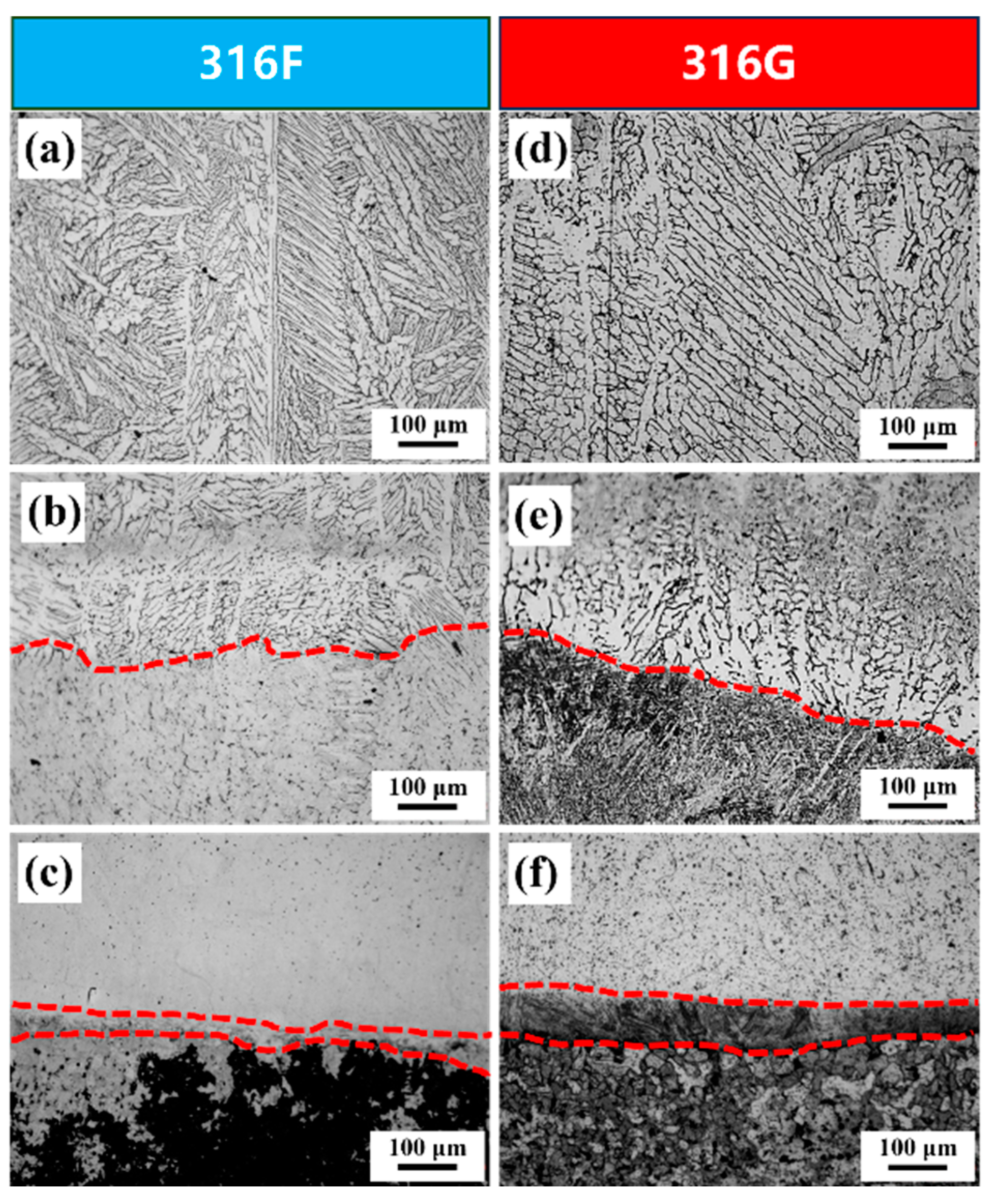
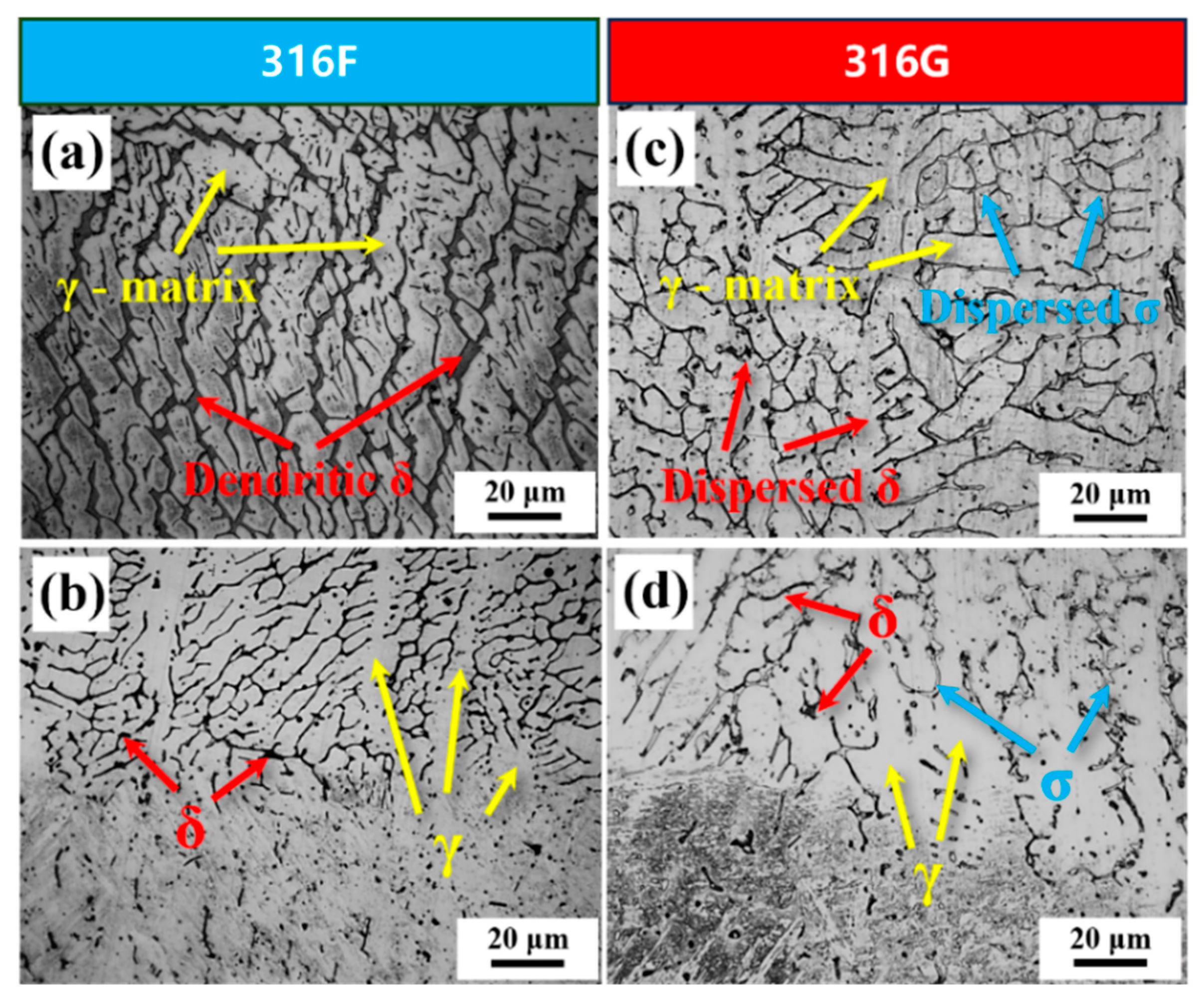
2.1. Microstructure and Physical Analysis
2.2. Electrochemical Corrosion Behavior
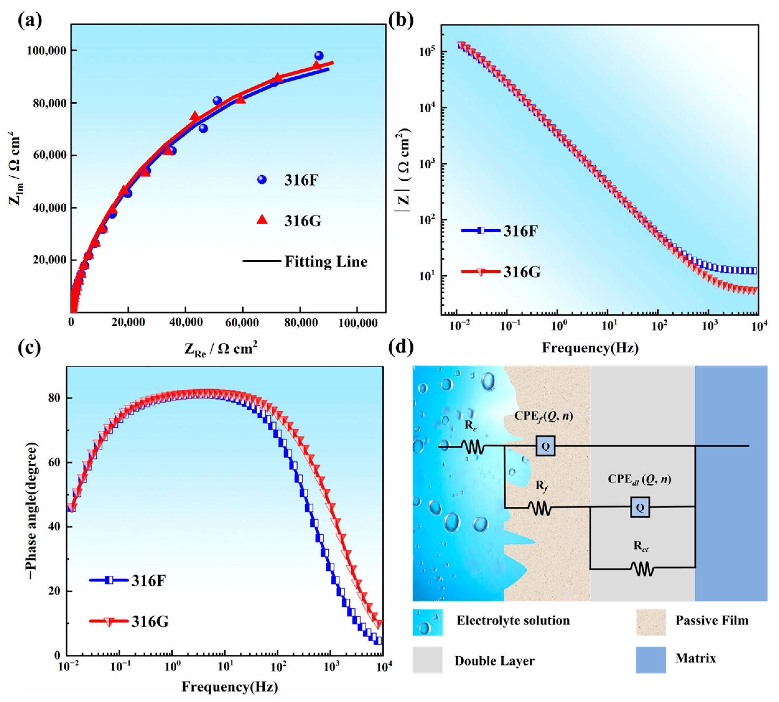
2.2.1. Electrochemical Impedance
2.2.2. Potentiodynamic Polarization
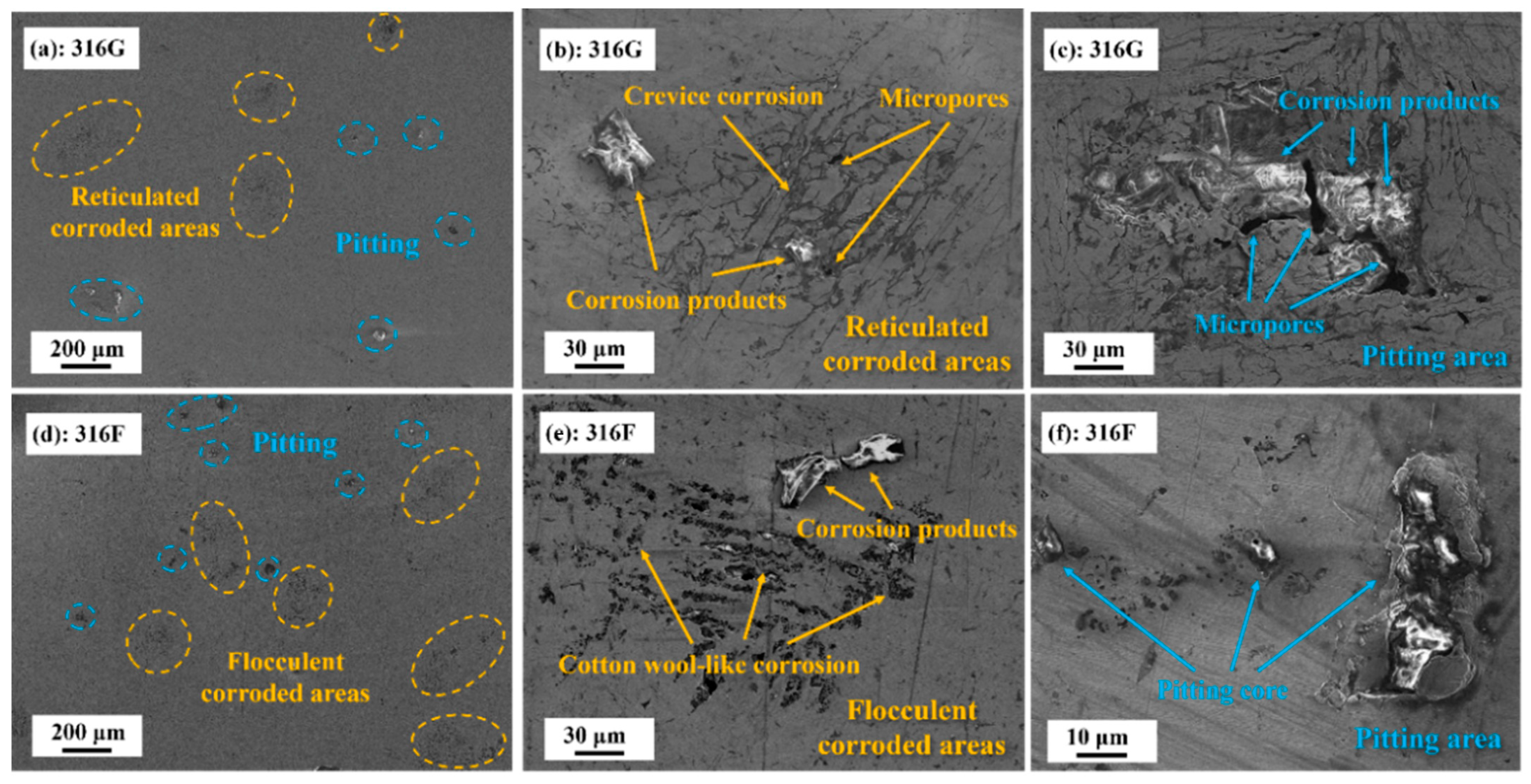
2.2.3. Corrosion Morphology and Corrosion Mechanism
- (1)
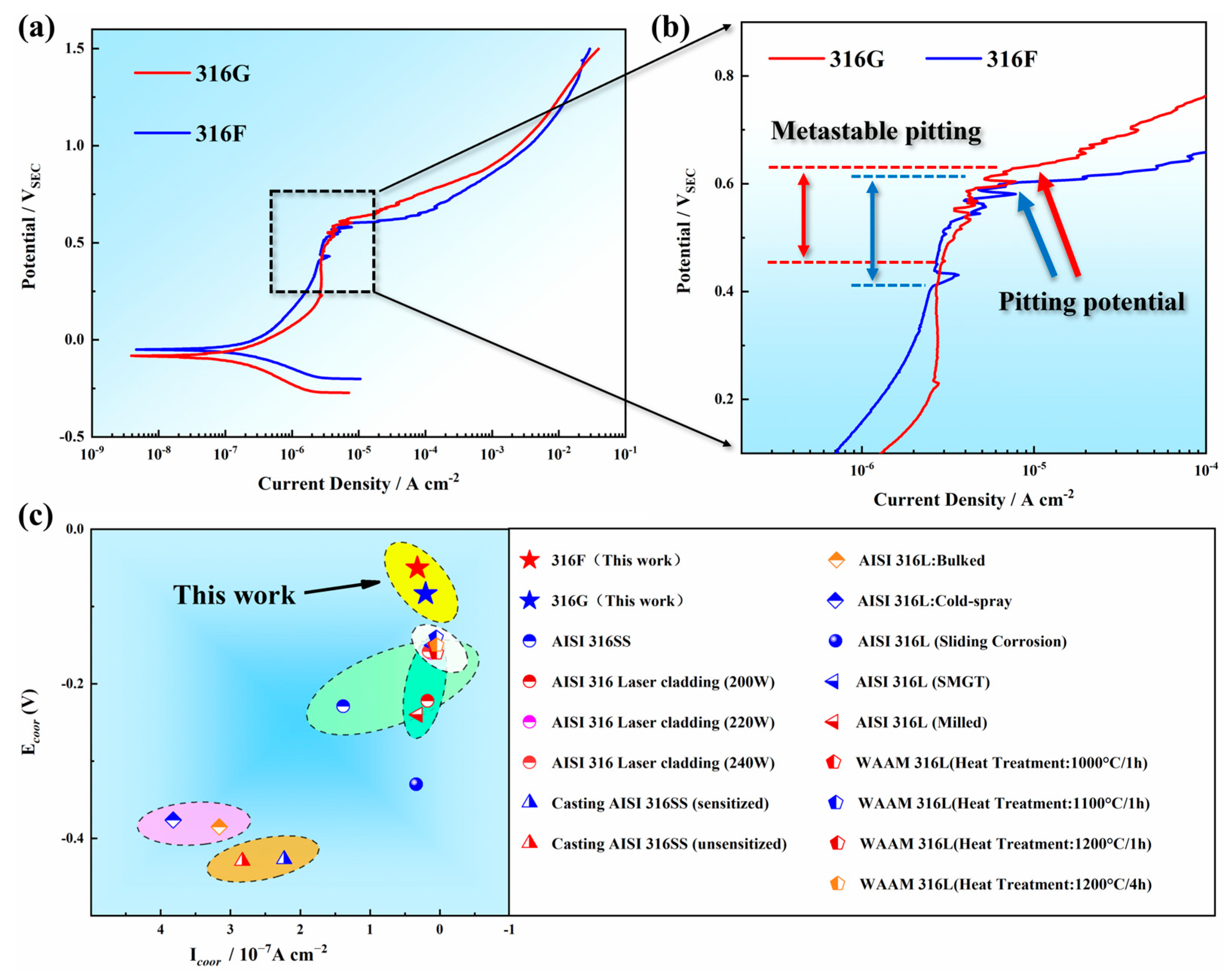
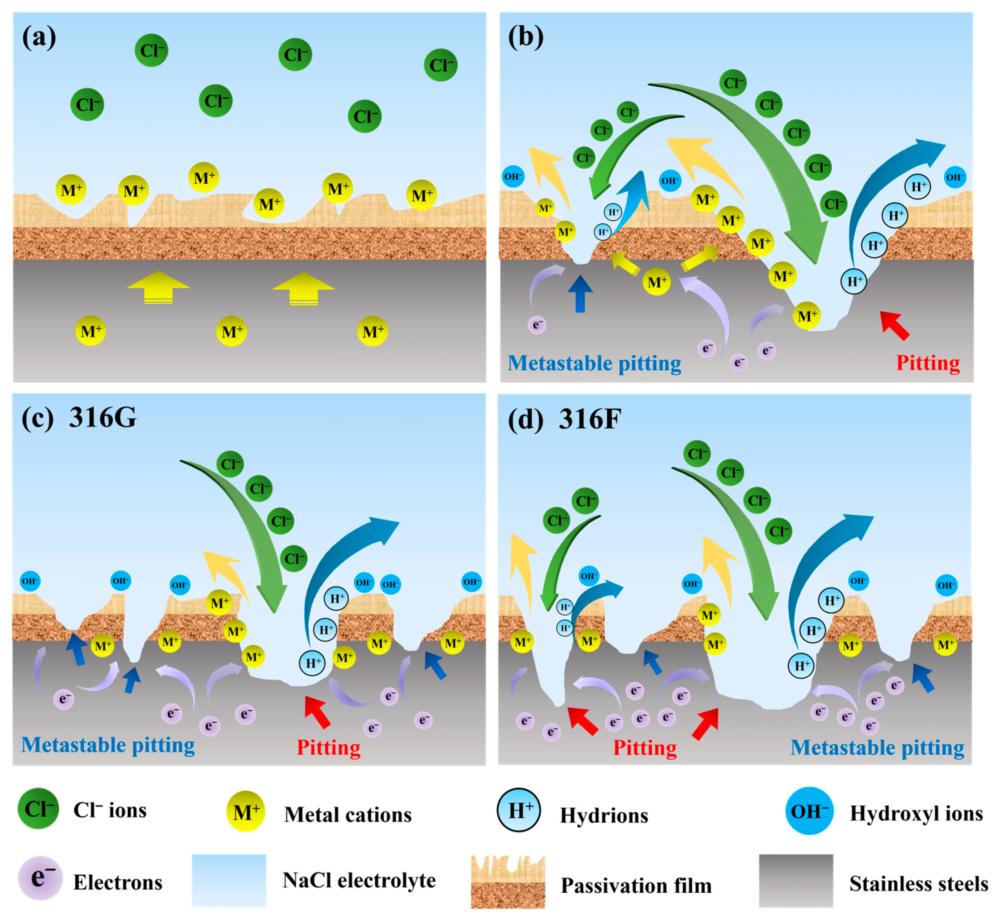
- When the “demand” is less than the “supply capability,” the potential difference between the cathode and the anode of stainless steel is stable, thus the corrosion current density remains almost constant. In the present work, this result was validated in the polarization curves for corrosion potentials of 0.3~0.43 V, as shown in Figure 6b.
- (2)
- The passivation film becomes unstable when the “demand” approaches the “supply capability,” as illustrated on the left half of Figure 8b. The voltage between two poles of stainless steel increases and drops instantaneously as the passivation film is penetrated or repaired, which results in a steep increase in the magnitude of the corrosion current density. This phenomenon is described as metastable pitting, which corresponds to the polarization curves in Figure 6b with corrosion potentials of 0.5~0.62 V.
- (3)
- When the “demand” exceeds the “supply capability,” the passivation film will be completely punctured, and the stainless steel enters the pitting phase, as shown in the right half of Figure 8b. Thenceforth, even a small increase in corrosion potential will bring about a surge in corrosion current density, which was reflected in the polarization curves after 0.62 V in the present work (shown in Figure 6a).
2.3. Mechanical Properties
3. Experiment
3.1. Material Modification
3.2. Sample Preparation
3.3. Microstructure Characterization
3.4. Electrochemical Test
3.5. Mechanical Properties Test
4. Conclusions
- (1)
- 316G exhibits better corrosion resistance than 316F based on conducted potentiodynamic polarization testing and corrosion morphology observation, which is mainly manifested in lower corrosion current density (icorr), higher pitting potential (Eb), and milder corrosion morphology.
- (2)
- The passivation process of stainless steel is essentially a change in the “supply” and “demand” of metal cations. The element Cr shows excellent ability to gain and lose electrons during corrosion, which is conducive to protecting the passivation film from being punctured, thus improving the corrosion resistance of stainless steel.
- (3)
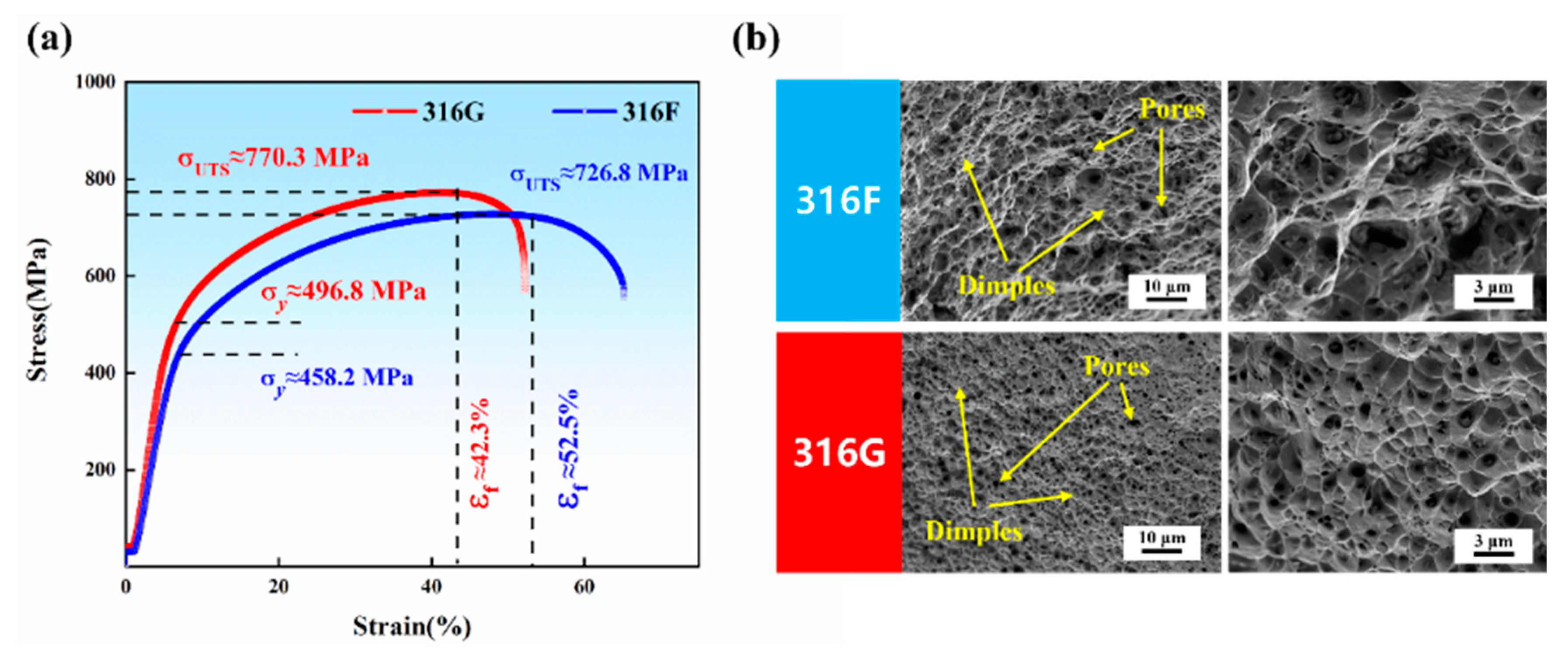
- 316F exhibits a tensile strength of 726.8 MPa and a yield strength of 458.2 MPa, along with an exceptionally high elongation of 52.5%. However, as the EEC is boosted with elevated Cr, the hard phase σ-Fe is formed as a reinforcing phase in 316G, contributing to its higher tensile (770.3 MPa) and yield (496.8 MPa) strengths while reducing its plasticity (42.3%).
Author Contributions
Funding
Institutional Review Board Statement
Informed Consent Statement
Data Availability Statement
Conflicts of Interest
References
- Gu, Y.; Xu, Y.; Shi, Y.; Feng, C.; Volodymyr, K.J.S.; Technology, C. Corrosion resistance of 316 stainless steel in a simulated pressurized water reactor improved by laser cladding with chromium. Surf. Coat. Technol. 2022, 441, 128534. [Google Scholar] [CrossRef]
- Mukahiwa, K.; Scenini, F.; Burke, M.G.; Platts, N.; Tice, D.; Stairmand, J.J.C.S. Corrosion fatigue and microstructural characterisation of Type 316 austenitic stainless steels tested in PWR primary water. Corros. Sci. 2018, 131, 57–70. [Google Scholar] [CrossRef]
- Zinkle, S.J.; Was, G.J. Materials challenges in nuclear energy. Acta Mater. 2013, 61, 735–758. [Google Scholar] [CrossRef]
- Wang, S.; Hu, Y.; Fang, K.; Zhang, W.; Wang, X. Effect of surface machining on the corrosion behaviour of 316 austenitic stainless steel in simulated PWR water. Corros. Sci. 2017, 126, 104–120. [Google Scholar] [CrossRef]
- Jung, K.; Ahn, S.; Kim, Y.; Oh, S.; Ryu, W.-H.; Kwon, H. Alloy design employing high Cr concentrations for Mo-free stainless steels with enhanced corrosion resistance. Corros. Sci. 2018, 140, 61–72. [Google Scholar] [CrossRef]
- Jiang, Y.; Tan, H.; Wang, Z.; Hong, J.; Jiang, L.; Li, J. Influence of Cr-eq/Ni-eq on pitting corrosion resistance and mechanical properties of UNS S32304 duplex stainless steel welded joints. Corros. Sci. 2013, 70, 252–259. [Google Scholar] [CrossRef]
- Hung, T.-S.; Chen, T.-C.; Chen, H.-Y.; Tsay, L.-W. The effects of Cr and Ni equivalents on the microstructure and corrosion resistance of austenitic stainless steels fabricated by laser powder bed fusion. J. Manuf. Process. 2023, 90, 69–79. [Google Scholar] [CrossRef]
- Kim, Y.H.; Lee, D.J.; Byun, J.C.; Jung, K.H.; Kim, J.I.; Lee, H.J.; Shin, Y.T.; Kim, S.H.; Lee, H.W. The effect of sigma phases formation depending on Cr/Ni equivalent ratio in AISI 316L weldments. Mater. Des. 2011, 32, 330–336. [Google Scholar] [CrossRef]
- Barcik, J. Mechanism of σ-phase precipitation in Cr–Ni austenitic steels. Mater. Sci. Technol. 1988, 4, 5–15. [Google Scholar] [CrossRef]
- Villanueva, D.M.E.; Junior, F.C.P.; Plaut, R.L.; Padilha, A.F. Comparative study on sigma phase precipitation of three types of stainless steels: Austenitic, superferritic and duplex. Mater. Sci. Technol. 2006, 22, 1098–1104. [Google Scholar] [CrossRef]
- Que, Z.; Chang, L.; Saario, T.; Bojinov, M. Localised electrochemical processes on laser powder bed fused 316 stainless steel with various heat treatments in high-temperature water. Addit. Manuf. 2022, 60, 103205. [Google Scholar] [CrossRef]
- Zhang, X.; Yang, D.; Jia, Y.; Wang, G.; Prashanth, K.G. Microstructure evolution and tensile property of high entropy alloy particle reinforced 316 L stainless steel matrix composites fabricated by laser powder bed fusion. J. Alloys Compd. 2023, 965, 171430. [Google Scholar] [CrossRef]
- Kim, D.W.; Ryu, W.S.; Hong, J.H.; Choi, S.K. Effect of nitrogen on high temperature low cycle fatigue behaviors in type 316L stainless steel. J. Nucl. Mater. 1998, 254, 226–233. [Google Scholar] [CrossRef]
- Ha, H.-Y.; Seo, W.-G.; Park, J.Y.; Lee, T.-H.; Kim, S. Influences of Mo on stress corrosion cracking susceptibility of newly developed FeCrMnNiNC-based lean austenitic stainless steels. Mater. Charact. 2016, 119, 200–208. [Google Scholar] [CrossRef]
- Li, X.; Gao, M.; Li, H.; Xing, W.; Zhang, L.; Shu, L.; Zhao, X.; Ma, Y.; Liu, K. Effect of residual hydrogen content on the tensile properties and crack propagation behavior of a type 316 stainless steel. Int. J. Hydrogen Energy 2019, 44, 25054–25063. [Google Scholar]
- Yao, Y.; Chen, A.; Wang, F.; Jiang, H.; Li, G.; Cui, J. Mechanical properties and joining mechanisms of magnetic pulse welding joints of additively manufactured 316L and conventional AA5052 aluminum alloy. J. Mater. Res. Technol. 2023, 26, 6146–6161. [Google Scholar] [CrossRef]
- Vora, J.; Parmar, H.; Chaudhari, R.; Khanna, S.; Doshi, M.; Patel, V. Experimental investigations on mechanical properties of multi-layered structure fabricated by GMAW-based WAAM of SS316L. J. Mater. Res. Technol. 2022, 20, 2748–2757. [Google Scholar] [CrossRef]
- Guo, S.; Xu, J.; Gu, J.; Peng, Y.; Zhou, Q.; Wang, K. Effect of cellular structure on the mechanical properties of 316L stainless steel fabricated by EBF3. J. Mater. Res. Technol. 2023, 25, 5469–5482. [Google Scholar] [CrossRef]
- Nazir, A.; Gokcekaya, O.; Billah, K.M.M.; Ertugrul, O.; Jiang, J.; Sun, J.; Hussain, S. Multi-material additive manufacturing: A systematic review of design, properties, applications, challenges, and 3D Printing of materials and cellular metamaterials. Mater. Des. 2023, 226, 111661. [Google Scholar] [CrossRef]
- Mostafaei, A.; Elliott, A.M.; Barnes, J.E.; Li, F.; Tan, W.; Cramer, C.L.; Nandwana, P.; Chmielus, M. Binder jet 3D printing—Process parameters, materials, properties, modeling, and challenges. Prog. Mater. Sci. 2021, 119, 100707. [Google Scholar] [CrossRef]
- Mostafaei, A.; Zhao, C.; He, Y.; Ghiaasiaan, S.R.; Shi, B.; Shao, S.; Shamsaei, N.; Wu, Z.; Kouraytem, N.; Sun, T.; et al. Defects and anomalies in powder bed fusion metal additive manufacturing. Curr. Opin. Solid State Mater. Sci. 2022, 26, 100974. [Google Scholar]
- Golgovici, F.; Tudose, A.E.; Diniasi, D.; Nartita, R.; Fulger, M.; Demetrescu, I. Aspects of Applied Chemistry Related to Future Goals of Safety and Efficiency in Materials Development for Nuclear Energy. Molecules 2023, 28, 874. [Google Scholar] [CrossRef] [PubMed]
- Kanishka, K.; Acherjee, B. A systematic review of additive manufacturing-based remanufacturing techniques for component repair and restoration. J. Manuf. Process. 2023, 89, 220–283. [Google Scholar] [CrossRef]
- Kucita, P.; Wang, S.; Li, W.; Cook, R.; Starink, M. The effects of substrate dilution on the microstructure and wear resistance of PTA Cu-Al-Fe aluminium bronze coatings. Wear 2019, 440, 203102. [Google Scholar] [CrossRef]
- Zhang, B.; Wang, H.; Zhang, S.; He, B. Optimization of the dilution parameters to improve wear resistance of laser cladding 15-5PH steel coating on U75V pearlitic steel. Surf. Coat. Technol. 2023, 465, 129571. [Google Scholar] [CrossRef]
- Zhong, J.; Hou, B.; Zhang, W.; Zhang, S.; Zhao, Y.; Zhao, C.; Li, W. High Hardness, Excellent Hydrophobicity, and Favorable Corrosion Resistance of Plasma-Sprayed FeCrMoSi Amorphous Coatings on 304 Stainless Steel. Molecules 2023, 28, 6718. [Google Scholar] [CrossRef]
- David, S.; Vitek, J. Correlation between solidification parameters and weld microstructures. Int. Mater. Rev. 1989, 34, 213–245. [Google Scholar] [CrossRef]
- Hwang, S.; Oh, W.-J.; Kim, D.-H.; Kim, J.G.; Oh, J.S.; Nam, T.-H.; Kim, C.-S.; Lee, T. Optimizing interlayer cooling for SUS316L thin wall fabricated by directed energy deposition. J. Mater. Res. Technol. 2023, 23, 5239–5245. [Google Scholar] [CrossRef]
- Tseng, C.C.; Shen, Y.; Thompson, S.W.; Mataya, M.C.; Krauss, G. Fracture and the formation of sigma phase, M23C6, and austenite from delta-ferrite in an AlSl 304L stainless steel. Metall. Mater. Trans. A 1994, 25, 1147–1158. [Google Scholar] [CrossRef]
- Marin, R.; Combeau, H.; Zollinger, J.; Dehmas, M.; Lhenry-Robert, L. σ-Phase Formation in Super Austenitic Stainless Steel During Directional Solidification and Subsequent Phase Transformations. Metall. Mater. Trans. A 2020, 51, 3526–3534. [Google Scholar] [CrossRef]
- Lescur, A.; Stergar, E.; Lim, J.; Hertelé, S.; Petrov, R.H. Microstructural investigation and identification of intermetallic σ-phase in solution annealed 316L-type austenitic stainless steel. Mater. Charact. 2021, 182, 111524. [Google Scholar] [CrossRef]
- Wu, M.; Jiang, F. Preparation, interface properties and corrosion behavior of nano-modified MAO ceramic film on 5B70 Al alloy. J. Alloys Compd. 2023, 967, 171829. [Google Scholar] [CrossRef]
- Gharouel, S.; Béguin, F. Revisiting the performance of electrical double-layer capacitors implementing a sodium perchlorate water-in-salt electrolyte. Electrochim. Acta 2023, 450, 142212. [Google Scholar] [CrossRef]
- Wang, Y.; Xiao, W.; Ma, K.; Dai, C.; Wang, D.; Wang, J.; Pan, F. Towards development of anticorrosive CaCO3-coated passive layer on Mg alloy with ultrasound-assisted electrodeposition. Corros. Sci. 2023, 224, 111546. [Google Scholar] [CrossRef]
- da Cunha Belo, M.; Walls, M.; Hakiki, N.; Corset, J.; Picquenard, E.; Sagon, G.; Noel, D. Composition, structure and properties of the oxide films formed on the stainless steel 316L in a primary type PWR environment. Corros. Sci. 1998, 40, 447–463. [Google Scholar] [CrossRef]
- Hirschorn, B.; Orazem, M.E.; Tribollet, B.; Vivier, V.; Frateur, I.; Musiani, M. Determination of effective capacitance and film thickness from constant-phase-element parameters. Electrochim. Acta 2010, 55, 6218–6227. [Google Scholar] [CrossRef]
- Quiones, A.O.; Bhuiyan, L.B.; Abbas, Z.; Outhwaite, C.W. Influence of concentration and temperature dependent dielectric constants on the thermodynamics of electrolytes. J. Mol. Liq. 2023, 371, 121119. [Google Scholar] [CrossRef]
- Tang, Y.; Zuo, Y.; Wang, J.; Zhao, X.; Niu, B.; Lin, B. The metastable pitting potential and its relation to the pitting potential for four materials in chloride solutions. Corros. Sci. 2014, 80, 111–119. [Google Scholar] [CrossRef]
- Zhang, Z.; Zhao, Z.; Li, X.; Wang, L.; Liu, B.; Bai, P. Effect of heat treatments on metastable pitting of 316L stainless steel fabricated by selective laser melting. J. Mater. Res. Technol. 2022, 21, 1903–1914. [Google Scholar] [CrossRef]
- Verma, J.; Taiwade, R.V. Dissimilar welding behavior of 22% Cr series stainless steel with 316L and its corrosion resistance in modified aggressive environment. J. Manuf. Process. 2016, 24, 1–10. [Google Scholar] [CrossRef]
- Javidi, M.; Haghshenas, S.M.S.; Shariat, M.H. CO2 corrosion behavior of sensitized 304 and 316 austenitic stainless steels in 3.5 wt.% NaCl solution and presence of H2S. Corros. Sci. 2020, 163, 108230. [Google Scholar] [CrossRef]
- Yang, C.; Jiang, X.; Zhang, W.; Wang, X. Enhancing stress corrosion cracking resistance of machined surface via surface mechanical grinding treatment for AISI 316 L stainless steel. Mater. Charact. 2022, 194, 112493. [Google Scholar] [CrossRef]
- Niu, D.; Zhang, C.; Sui, X.; Lu, X.; Zhang, X.; Wang, C.; Hao, J.; Shi, Z. Microstructure, mechanical properties and tribo-corrosion mechanism of (CrNbTiAlVMo)xN1−x coated 316 L stainless steel in 3.5 wt.% NaCl solution. Tribol. Int. 2022, 173, 107638. [Google Scholar] [CrossRef]
- Chen, X.; Li, J.; Cheng, X.; Wang, H.; Huang, Z. Effect of heat treatment on microstructure, mechanical and corrosion properties of austenitic stainless steel 316L using arc additive manufacturing. Mater. Sci. Eng. A 2018, 715, 307–314. [Google Scholar] [CrossRef]
- Ralls, A.M.; Daroonparvar, M.; Sikdar, S.; Rahman, M.H.; Monwar, M.; Watson, K.; Kay, C.M.; Menezes, P.L. Tribological and corrosion behavior of high pressure cold sprayed duplex 316 L stainless steel. Tribol. Int. 2022, 169, 107471. [Google Scholar] [CrossRef]
- Li, X.; Sun, W.; Zheng, Y.; Long, C.; Wang, Q. New Strategy for the Design of Anti-Corrosion Coatings in Bipolar Plates Based on Hybrid Organic–Inorganic Layers. Molecules 2023, 28, 3279. [Google Scholar] [CrossRef]
- Chen, M.; Yang, K.; Wang, Z.; Zhao, K.; Wu, E.; Shi, J.; Qi, H.; Sun, G. Corrosion performance of NV E690 steel and 316L stainless steel coating fabricated by underwater direct metal deposition. Corros. Sci. 2023, 219, 111232. [Google Scholar] [CrossRef]
- Xu, L.; Wu, P.; Zhu, X.; Zhao, G.; Ren, X.; Wei, Q.; Xie, L. Structural characteristics and chloride intrusion mechanism of passive film. Corros. Sci. 2022, 207, 110563. [Google Scholar] [CrossRef]
- Srinivasan, G.; Bhaduri, A.; Shankar, V.; Raj, B. Evaluation of hot cracking susceptibility of some austenitic stainless steels and a nickel-base alloy. Weld. World 2008, 52, 4–17. [Google Scholar] [CrossRef]


| Specimen | Re (Ω·cm2) | Rf (Ω·cm2) | CPEf | Rct (Ω·cm2) | CPEdl | Chi-Square | ||
|---|---|---|---|---|---|---|---|---|
| γ (Ω−1·cm−2·s−n) | n | γ (Ω−1·cm−2·s−n) | n | |||||
| 316F | 12.14 | 35.08 | 2.495 × 10⁻⁵ | 0.9806 | 2.31 × 10⁵ | 2.93 × 10⁻⁵ | 0.8228 | 0.000331 |
| 316G | 5.46 | 44.03 | 2.761 × 10⁻⁵ | 0.9720 | 2.33 × 10⁵ | 2.48 × 10⁻⁵ | 0.8322 | 0.000617 |
| Specimen | 316F | 316G |
|---|---|---|
| Cpass/F·cm−2 | 4.43 × 10⁻⁵ | 3.49 × 10⁻⁵ |
| δ/nm | 1.559 | 1.985 |
| Specimen | icorr/μA·cm−2 | Ecorr/V | Eb/V | PREN |
|---|---|---|---|---|
| 316F | 0.32117 | −0.0499 | 0.603 | 28.9% |
| 316G | 0.20447 | −0.0833 | 0.634 | 31.9% |
| Materials | C | Si | Mn | Cr | Ni | Mo | P | S | Nb | Fe |
|---|---|---|---|---|---|---|---|---|---|---|
| 316G | 0.08 | 0.75 | 2 | 22 | 14 | 3 | ≤0.2 | ≤0.25 | 0 | Bal. |
| 316F | 0.08 | 0.75 | 2 | 19 | 12 | 3 | ≤0.2 | ≤0.25 | 0 | Bal. |
| 316 | ≤0.08 | ≤1 | ≤2 | 16~18 | 10~14 | 2~3 | ≤0.045 | ≤0.03 | 0 | Bal. |
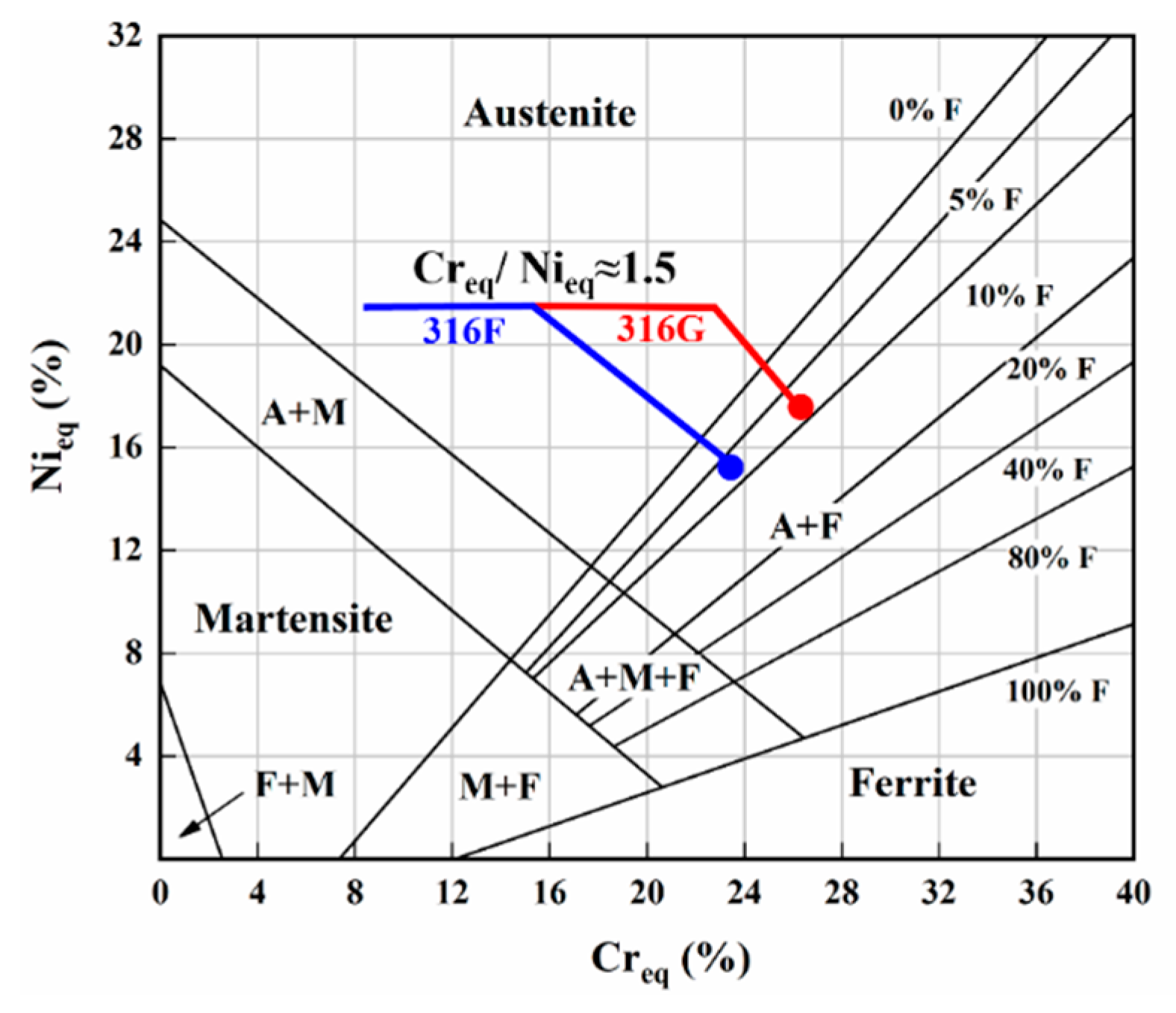
| Specimen | Creq | Nieq | Creq/Nieq |
|---|---|---|---|
| 316F | 23.13 | 15.4 | 1.5019 |
| 316G | 26.13 | 17.4 | 1.5017 |
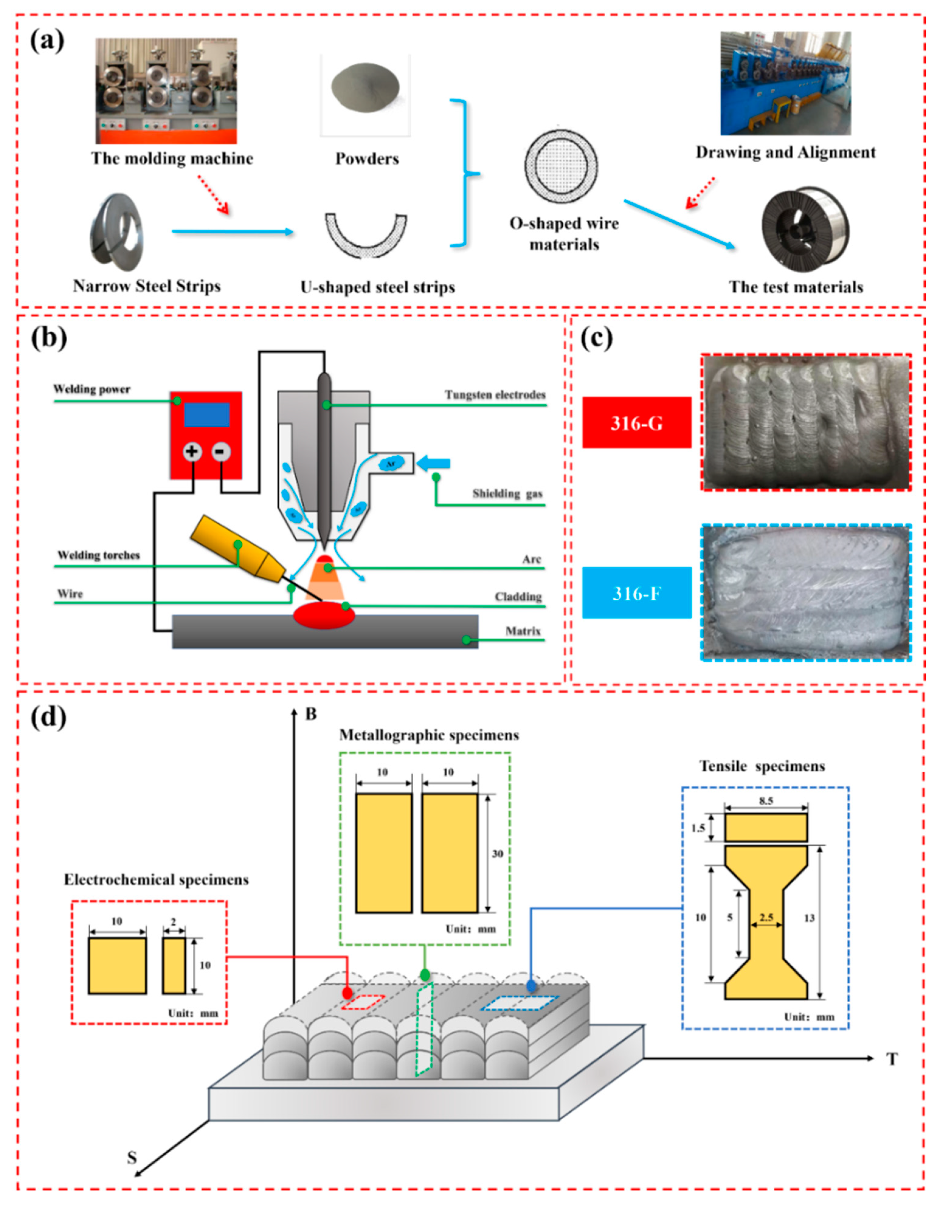
| Cladding Manner | Cladding Current /A | Cladding Voltage /V | Cladding Rate /mm·s−1 | Shielding Gas Rate /L·min−1 |
|---|---|---|---|---|
| TIG | 200 | 18 | 2.5 | 15 |
Disclaimer/Publisher’s Note: The statements, opinions and data contained in all publications are solely those of the individual author(s) and contributor(s) and not of MDPI and/or the editor(s). MDPI and/or the editor(s) disclaim responsibility for any injury to people or property resulting from any ideas, methods, instructions or products referred to in the content. |
© 2024 by the authors. Licensee MDPI, Basel, Switzerland. This article is an open access article distributed under the terms and conditions of the Creative Commons Attribution (CC BY) license (https://creativecommons.org/licenses/by/4.0/).
Share and Cite
Zhang, P.; Jian, H.; Yin, L.; Liu, J.; Cai, Z.; Tong, Y. Corrosion Resistance and Mechanical Properties of Cr-Rich 316 Stainless Steel Coatings Fabricated by the TIG Process Using Flux-Cored Wires. Molecules 2024, 29, 1785. https://doi.org/10.3390/molecules29081785
Zhang P, Jian H, Yin L, Liu J, Cai Z, Tong Y. Corrosion Resistance and Mechanical Properties of Cr-Rich 316 Stainless Steel Coatings Fabricated by the TIG Process Using Flux-Cored Wires. Molecules. 2024; 29(8):1785. https://doi.org/10.3390/molecules29081785
Chicago/Turabian StyleZhang, Peng, Huaian Jian, Lairong Yin, Jian Liu, Zhihai Cai, and Yonggang Tong. 2024. "Corrosion Resistance and Mechanical Properties of Cr-Rich 316 Stainless Steel Coatings Fabricated by the TIG Process Using Flux-Cored Wires" Molecules 29, no. 8: 1785. https://doi.org/10.3390/molecules29081785