

Design of Na3MnZr(PO4)3/Carbon Nanofiber Free-Standing Cathodes for Sodium-Ion Batteries with Enhanced Electrochemical Performances through Different Electrospinning Approaches


 ,
,  ,
,  ,
,  ,
,
Abstract
1. Introduction
2. Results
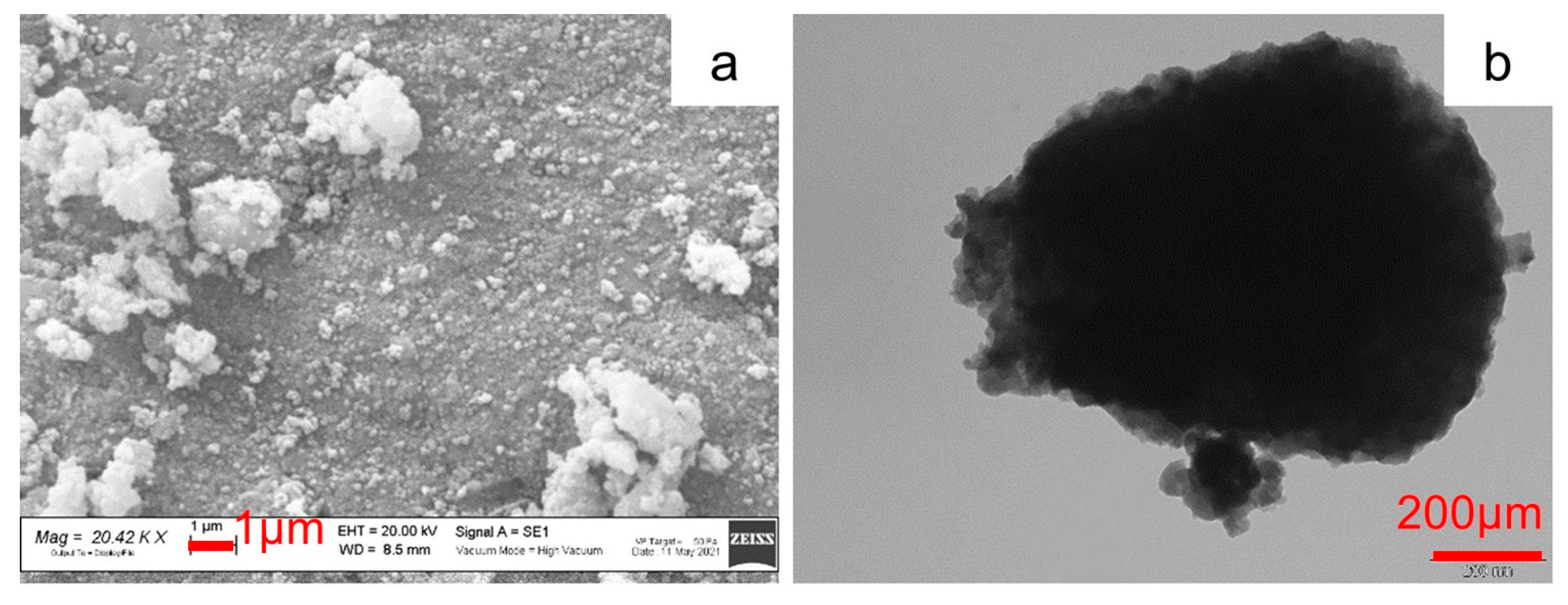
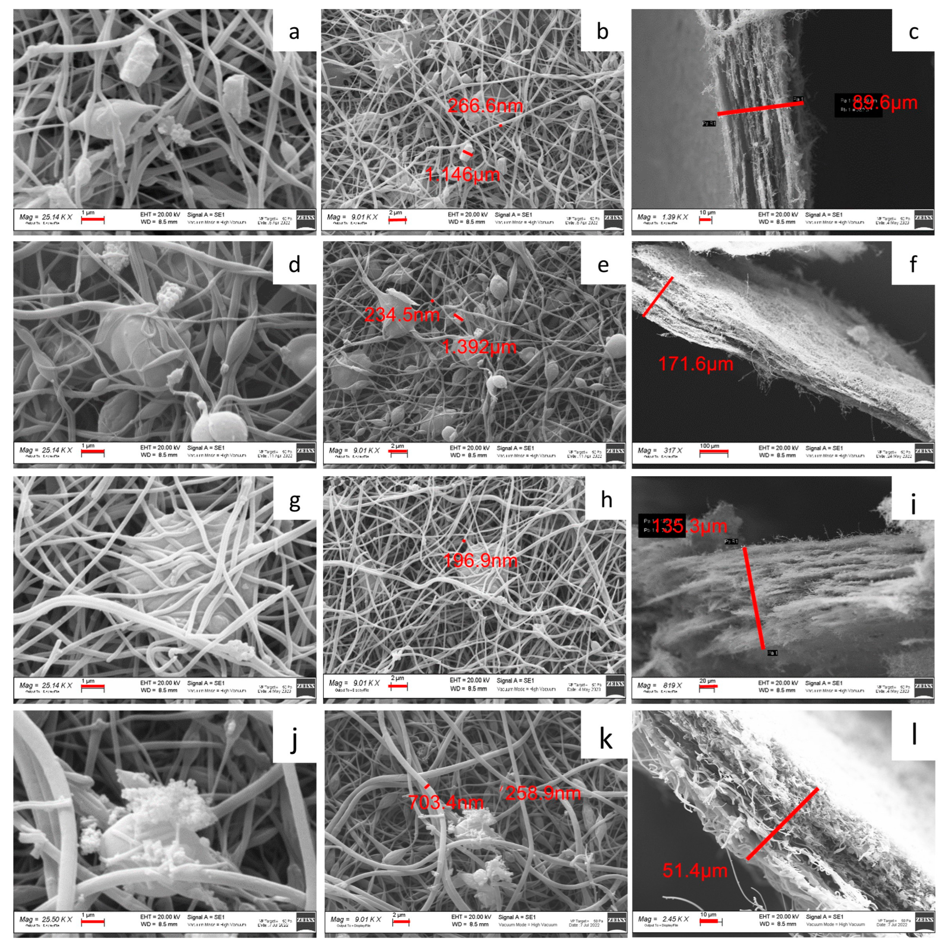
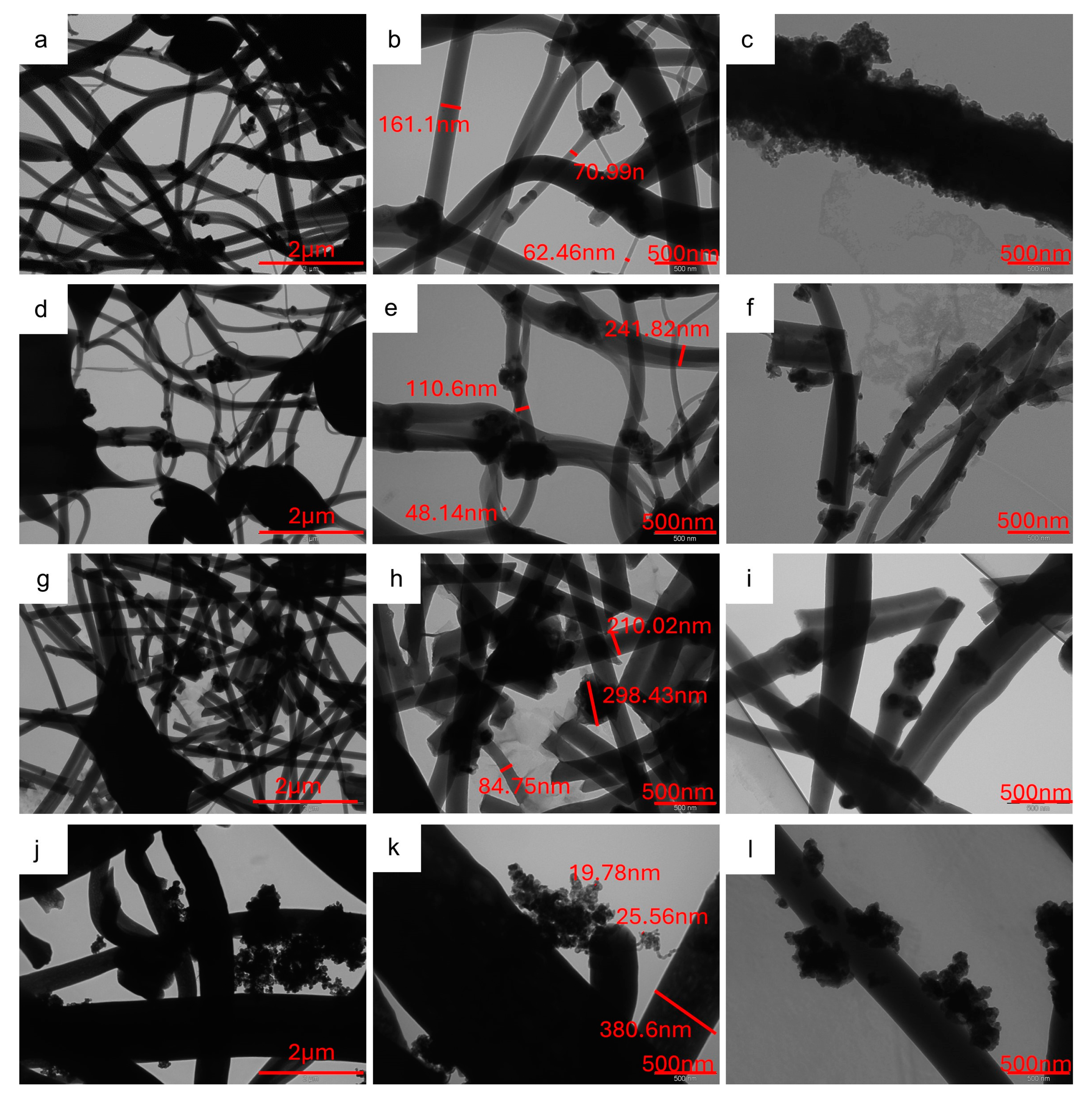
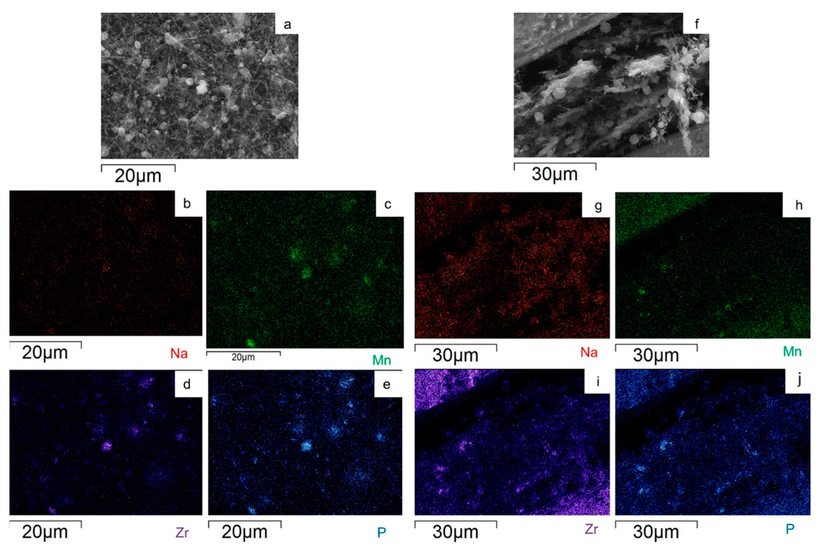
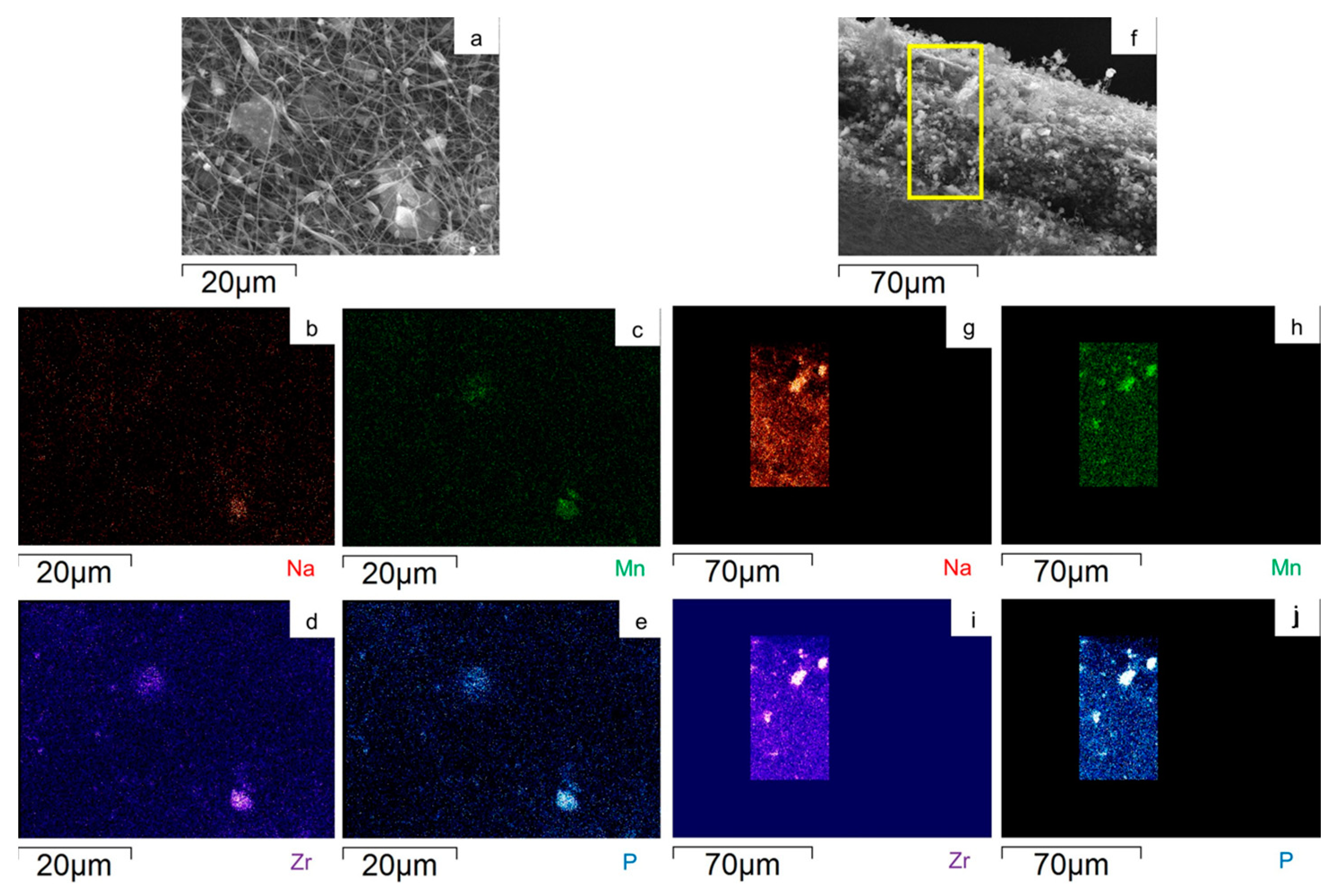
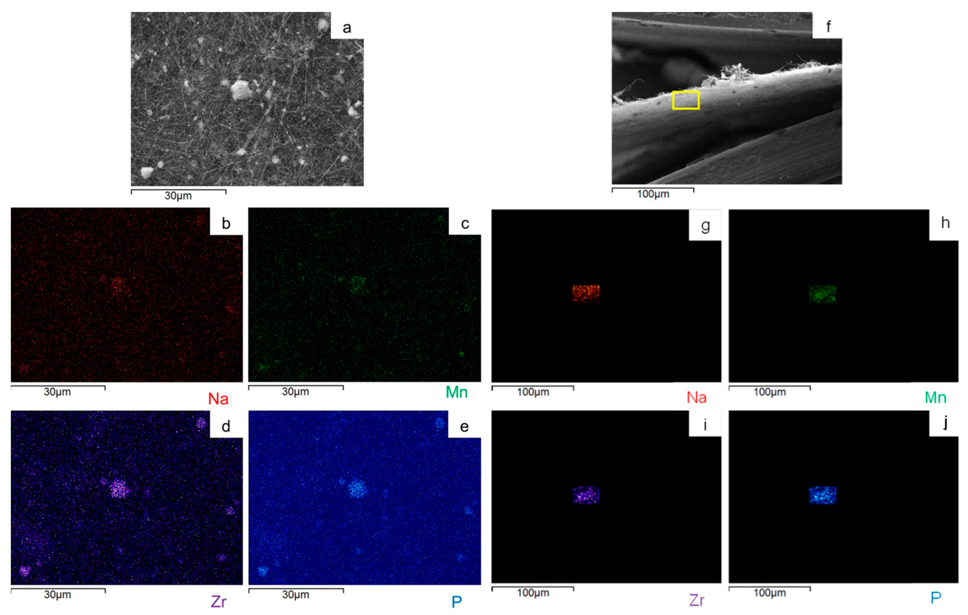
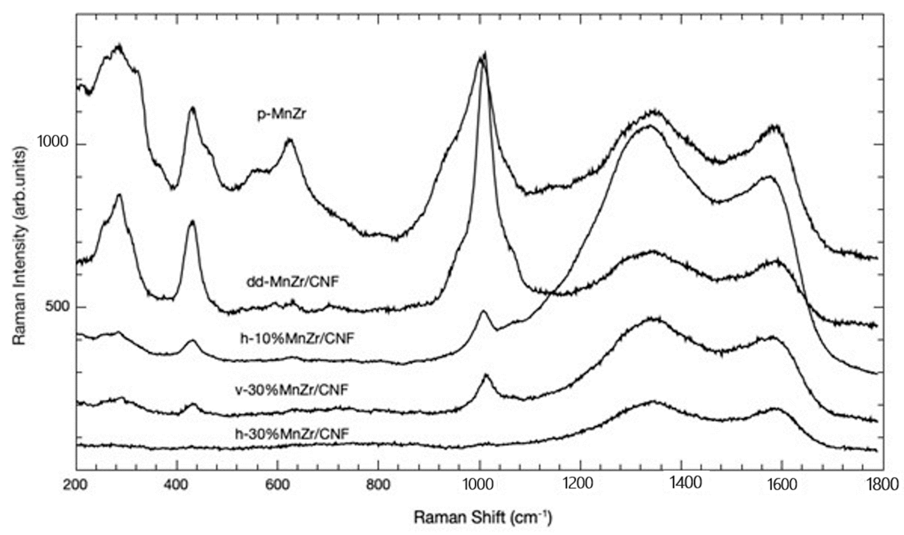
2.1. p-MnZr and MnZr/CNF Characterization
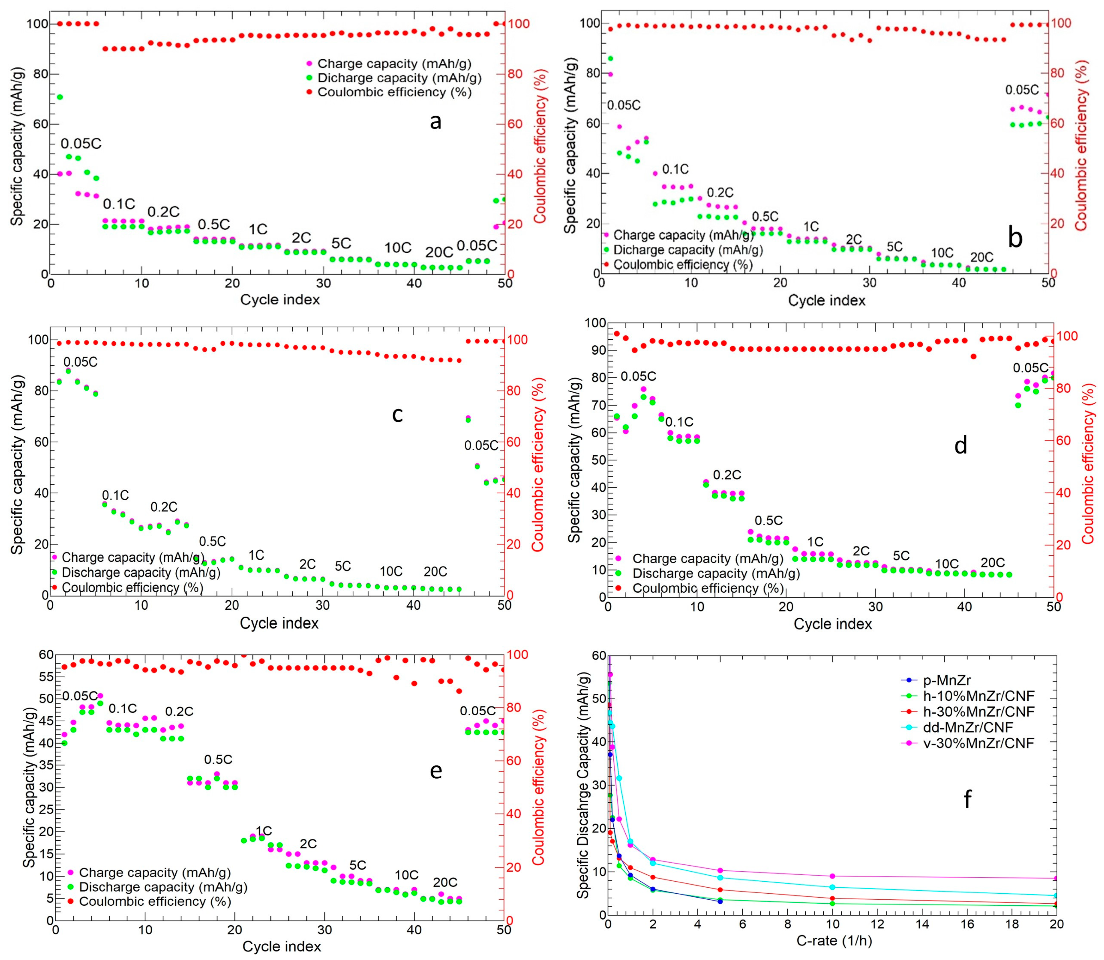
2.2. p-MnZr and MnZr/CNF Electrochemical Characterization
3. Materials and Methods
3.1. Materials
3.2. Synthesis
3.2.1. Active Material Na3MnZr(PO4)3
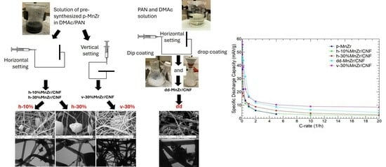
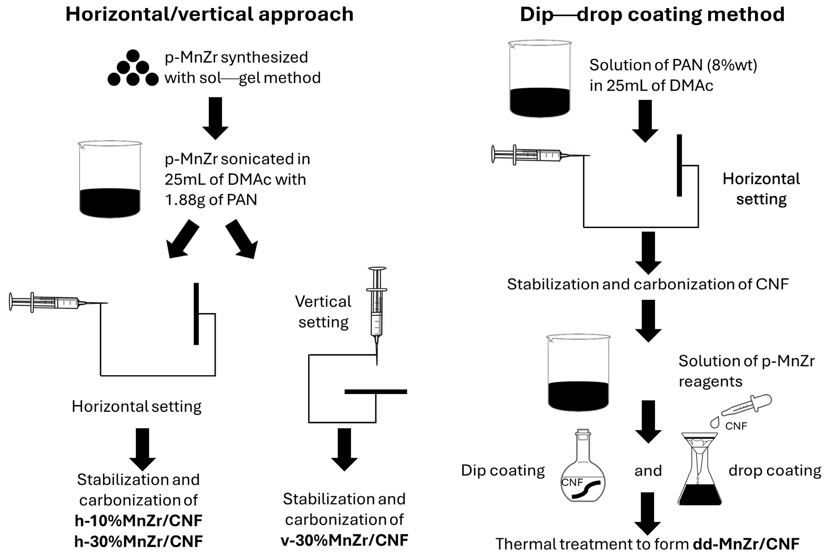
3.2.2. Self-Standing Cathodes
3.2.3. Tape-Cast Cathode
3.3. Cell Assembly
3.4. Characterization Techniques
4. Conclusions
Supplementary Materials
Author Contributions
Funding
Institutional Review Board Statement
Informed Consent Statement
Data Availability Statement
Acknowledgments
Conflicts of Interest
References
- Goodenough, J.B. Electrochemical Energy Storage in a Sustainable Modern Society. Energy Environ. Sci. 2013, 7, 14–18. [Google Scholar] [CrossRef]
- Larcher, D.; Tarascon, J.-M. Towards Greener and More Sustainable Batteries for Electrical Energy Storage. Nat. Chem. 2015, 7, 19–29. [Google Scholar] [CrossRef] [PubMed]
- Scrosati, B.; Hassoun, J.; Sun, Y.-K. Lithium-Ion Batteries. A Look into the Future. Energy Environ. Sci. 2011, 4, 3287–3295. [Google Scholar] [CrossRef]
- Gao, C.; Dong, Q.; Zhang, G.; Fan, H.; Li, H.; Hong, B.; Lai, Y. Antimony-Doped Lithium Phosphate Artificial Solid Electrolyte Interphase for Dendrite-Free Lithium-Metal Batteries. ChemElectroChem 2019, 6, 1134–1138. [Google Scholar] [CrossRef]
- Huang, Y.; Yang, H.; Xiong, T.; Adekoya, D.; Qiu, W.; Wang, Z.; Zhang, S.; Balogun, M.-S. Adsorption Energy Engineering of Nickel Oxide Hybrid Nanosheets for High Areal Capacity Flexible Lithium-Ion Batteries. Energy Storage Mater. 2020, 25, 41–51. [Google Scholar] [CrossRef]
- Balogun, M.-S.; Zeng, Y.; Qiu, W.; Luo, Y.; Onasanya, A.; Olaniyi, T.K.; Tong, Y. Three-Dimensional Nickel Nitride (Ni3N) Nanosheets: Free Standing and Flexible Electrodes for Lithium Ion Batteries and Supercapacitors. J. Mater. Chem. A 2016, 4, 9844–9849. [Google Scholar] [CrossRef]
- Balogun, M.-S.; Wu, Z.; Luo, Y.; Qiu, W.; Fan, X.; Long, B.; Huang, M.; Liu, P.; Tong, Y. High Power Density Nitridated Hematite (α-Fe2O3) Nanorods as Anode for High-Performance Flexible Lithium Ion Batteries. J. Power Sources 2016, 308, 7–17. [Google Scholar] [CrossRef]
- Tarascon, J.-M. Is Lithium the New Gold? Nature Chem. 2010, 2, 510. [Google Scholar] [CrossRef] [PubMed]
- Whittingham, M.S. Lithium Batteries and Cathode Materials. Chem. Rev. 2004, 104, 4271–4302. [Google Scholar] [CrossRef] [PubMed]
- Goodenough, J.B.; Park, K.-S. The Li-Ion Rechargeable Battery: A Perspective. J. Am. Chem. Soc. 2013, 135, 1167–1176. [Google Scholar] [CrossRef] [PubMed]
- Grosjean, C.; Miranda, P.H.; Perrin, M.; Poggi, P. Assessment of World Lithium Resources and Consequences of Their Geographic Distribution on the Expected Development of the Electric Vehicle Industry. Renew. Sustain. Energy Rev. 2012, 16, 1735–1744. [Google Scholar] [CrossRef]
- Kesler, S.E.; Gruber, P.W.; Medina, P.A.; Keoleian, G.A.; Everson, M.P.; Wallington, T.J. Global Lithium Resources: Relative Importance of Pegmatite, Brine and Other Deposits. Ore Geol. Rev. 2012, 48, 55–69. [Google Scholar] [CrossRef]
- Miedema, J.H.; Moll, H.C. Lithium Availability in the EU27 for Battery-Driven Vehicles: The Impact of Recycling and Substitution on the Confrontation between Supply and Demand Until 2050. Resour. Policy 2013, 38, 204–211. [Google Scholar] [CrossRef]
- Vaalma, C.; Buchholz, D.; Weil, M.; Passerini, S. A Cost and Resource Analysis of Sodium-Ion Batteries. Nat. Rev. Mater. 2018, 3, 18013. [Google Scholar] [CrossRef]
- Zhao, C.; Wang, Q.; Yao, Z.; Wang, J.; Sánchez-Lengeling, B.; Ding, F.; Qi, X.; Lu, Y.; Bai, X.; Li, B.; et al. Rational Design of Layered Oxide Materials for Sodium-Ion Batteries. Science 2020, 370, 708–711. [Google Scholar] [CrossRef] [PubMed]
- Liu, Y.; Liu, X.; Wang, T.; Fan, L.-Z.; Jiao, L. Research and Application Progress on Key Materials for Sodium-Ion Batteries. Sustain. Energy Fuels 2017, 1, 986–1006. [Google Scholar] [CrossRef]
- Han, M.H.; Gonzalo, E.; Singh, G.; Rojo, T. A Comprehensive Review of Sodium Layered Oxides: Powerful Cathodes for Na-Ion Batteries. Energy Environ. Sci. 2014, 8, 81–102. [Google Scholar] [CrossRef]
- Wang, P.-F.; You, Y.; Yin, Y.-X.; Guo, Y.-G. Layered Oxide Cathodes for Sodium-Ion Batteries: Phase Transition, Air Stability, and Performance. Adv. Energy Mater. 2018, 8, 1701912. [Google Scholar] [CrossRef]
- Zhou, Y.-N.; Wang, P.-F.; Niu, Y.-B.; Li, Q.; Yu, X.; Yin, Y.-X.; Xu, S.; Guo, Y.-G. A P2/P3 Composite Layered Cathode for High-Performance Na-Ion Full Batteries. Nano Energy 2019, 55, 143–150. [Google Scholar] [CrossRef]
- Xie, Y.; Wang, H.; Xu, G.; Wang, J.; Sheng, H.; Chen, Z.; Ren, Y.; Sun, C.-J.; Wen, J.; Wang, J.; et al. In Operando XRD and TXM Study on the Metastable Structure Change of NaNi1/3Fe1/3Mn1/3O2 under Electrochemical Sodium-Ion Intercalation. Adv. Energy Mater. 2016, 6, 1601306. [Google Scholar] [CrossRef]
- Wei, F.; Zhang, Q.; Zhang, P.; Tian, W.; Dai, K.; Zhang, L.; Mao, J.; Shao, G. Review—Research Progress on Layered Transition Metal Oxide Cathode Materials for Sodium Ion Batteries. J. Electrochem. Soc. 2021, 168, 050524. [Google Scholar] [CrossRef]
- Wang, H.; Zhou, L.; Cheng, Z.; Liu, L.; Wang, Y.; Du, T. Recent Advances on F-Doped Layered Transition Metal Oxides for Sodium Ion Batteries. Molecules 2023, 28, 8065. [Google Scholar] [CrossRef] [PubMed]
- Wang, L.; Lu, Y.; Liu, J.; Xu, M.; Cheng, J.; Zhang, D.; Goodenough, J.B. A Superior Low-Cost Cathode for a Na-Ion Battery. Angew. Chem. Int. Ed. 2013, 52, 1964–1967. [Google Scholar] [CrossRef] [PubMed]
- Lee, H.-W.; Wang, R.Y.; Pasta, M.; Woo Lee, S.; Liu, N.; Cui, Y. Manganese Hexacyanomanganate Open Framework as a High-Capacity Positive Electrode Material for Sodium-Ion Batteries. Nat. Commun. 2014, 5, 5280. [Google Scholar] [CrossRef] [PubMed]
- You, Y.; Wu, X.-L.; Yin, Y.-X.; Guo, Y.-G. High-Quality Prussian Blue Crystals as Superior Cathode Materials for Room-Temperature Sodium-Ion Batteries. Energy Environ. Sci. 2014, 7, 1643–1647. [Google Scholar] [CrossRef]
- Song, J.; Wang, L.; Lu, Y.; Liu, J.; Guo, B.; Xiao, P.; Lee, J.-J.; Yang, X.-Q.; Henkelman, G.; Goodenough, J.B. Removal of Interstitial H2O in Hexacyanometallates for a Superior Cathode of a Sodium-Ion Battery. J. Am. Chem. Soc. 2015, 137, 2658–2664. [Google Scholar] [CrossRef] [PubMed]
- Ren, W.; Qin, M.; Zhu, Z.; Yan, M.; Li, Q.; Zhang, L.; Liu, D.; Mai, L. Activation of Sodium Storage Sites in Prussian Blue Analogues via Surface Etching. Nano Lett. 2017, 17, 4713–4718. [Google Scholar] [CrossRef] [PubMed]
- Ma, X.; Pan, Z.; Wu, X.; Shen, P.K. Na4Fe3(PO4)2(P2O7)@NaFePO4@C Core-Double-Shell Architectures on Carbon Cloth: A High-Rate, Ultrastable, and Flexible Cathode for Sodium Ion Batteries. Chem. Eng. J. 2019, 365, 132–141. [Google Scholar] [CrossRef]
- Zhang, J.; Zhao, X.; Song, Y.; Li, Q.; Liu, Y.; Chen, J.; Xing, X. Understanding the Superior Sodium-Ion Storage in a Novel Na3.5Mn0.5V1.5(PO4)3 Cathode. Energy Storage Mater. 2019, 23, 25–34. [Google Scholar] [CrossRef]
- Liu, R.; Liang, Z.; Xiang, Y.; Zhao, W.; Liu, H.; Chen, Y.; An, K.; Yang, Y. Recognition of V3+/V4+/V5+ Multielectron Reactions in Na3V(PO4)2: A Potential High Energy Density Cathode for Sodium-Ion Batteries. Molecules 2020, 25, 1000. [Google Scholar] [CrossRef] [PubMed]
- Wang, C.; Du, D.; Song, M.; Wang, Y.; Li, F. A High-Power Na3V2(PO4)3-Bi Sodium-Ion Full Battery in a Wide Temperature Range. Adv. Energy Mater. 2019, 9, 1900022. [Google Scholar] [CrossRef]
- Xu, Y.; Wei, Q.; Xu, C.; Li, Q.; An, Q.; Zhang, P.; Sheng, J.; Zhou, L.; Mai, L. Layer-by-Layer Na3V2(PO4)3 Embedded in Reduced Graphene Oxide as Superior Rate and Ultralong-Life Sodium-Ion Battery Cathode. Adv. Energy Mater. 2016, 6, 1600389. [Google Scholar] [CrossRef]
- Li, F.; Zhu, Y.-E.; Sheng, J.; Yang, L.; Zhang, Y.; Zhou, Z. GO-Induced Preparation of Flake-Shaped Na3V2(PO4)3@rGO as High-Rate and Long-Life Cathodes for Sodium-Ion Batteries. J. Mater. Chem. A 2017, 5, 25276–25281. [Google Scholar] [CrossRef]
- Kawai, K.; Zhao, W.; Nishimura, S.; Yamada, A. High-Voltage Cr4+/Cr3+ Redox Couple in Polyanion Compounds. ACS Appl. Energy Mater. 2018, 1, 928–931. [Google Scholar] [CrossRef]
- Rajagopalan, R.; Chen, B.; Zhang, Z.; Wu, X.-L.; Du, Y.; Huang, Y.; Li, B.; Zong, Y.; Wang, J.; Nam, G.-H.; et al. Improved Reversibility of Fe3+/Fe4+ Redox Couple in Sodium Super Ion Conductor Type Na3Fe2(PO4)3 for Sodium-Ion Batteries. Adv. Mater. 2017, 29, 1605694. [Google Scholar] [CrossRef] [PubMed]
- Chen, K.; Shi, Q.; Wang, Y.; Li, X.; Jiang, Y.; Xu, H.; Guo, S.; Zhao, L.; Dai, C. Effects of Scandium Doping on the Electrochemical Performance of Cathode Materials Na3MnTi(PO4)3 for Sodium-Ion Batteries. Colloids Surf. A Physicochem. Eng. Asp. 2023, 662, 130996. [Google Scholar] [CrossRef]
- Li, H.; Xu, M.; Gao, C.; Zhang, W.; Zhang, Z.; Lai, Y.; Jiao, L. Highly Efficient, Fast and Reversible Multi-Electron Reaction of Na3MnTi(PO4)3 Cathode for Sodium-Ion Batteries. Energy Storage Mater. 2020, 26, 325–333. [Google Scholar] [CrossRef]
- Gao, H.; Seymour, I.D.; Xin, S.; Xue, L.; Henkelman, G.; Goodenough, J.B. Na3MnZr(PO4)3: A High-Voltage Cathode for Sodium Batteries. J. Am. Chem. Soc. 2018, 140, 18192–18199. [Google Scholar] [CrossRef] [PubMed]
- Liu, J.; Zhao, Y.; Huang, X.; Zhou, Y.; Lam, K.; Yu, D.Y.W.; Hou, X. NASICON-Structured Na3MnTi(PO4)2.83F0.5 Cathode with High Energy Density and Rate Performance for Sodium-Ion Batteries. Chem. Eng. J. 2022, 435, 134839. [Google Scholar] [CrossRef]
- Zhu, T.; Hu, P.; Cai, C.; Liu, Z.; Hu, G.; Kuang, Q.; Mai, L.; Zhou, L. Dual Carbon Decorated Na3MnTi(PO4)3: A High-Energy-Density Cathode Material for Sodium-Ion Batteries. Nano Energy 2020, 70, 104548. [Google Scholar] [CrossRef]
- Ma, X.; Wu, X.; Liu, Y.; Wu, W.; Pan, Z.; Shen, P.K. Toward a High-Energy-Density Cathode with Enhanced Temperature Adaptability for Sodium-Ion Batteries: A Case Study of Na3MnZr(PO4)3 Microspheres with Embedded Dual-Carbon Networks. ACS Appl. Mater. Interfaces 2021, 13, 21390–21400. [Google Scholar] [CrossRef] [PubMed]
- Sun, G.; Sun, L.; Xie, H.; Liu, J. Electrospinning of Nanofibers for Energy Applications. Nanomaterials 2016, 6, 129. [Google Scholar] [CrossRef] [PubMed]
- Liao, Q.; Kim, E.J.; Tang, Y.; Xu, H.; Yu, D.-G.; Song, W.; Kim, B.J. Rational Design of Hyper-Crosslinked Polymers for Biomedical Applications. J. Polym. Sci. 2023, 64, 8. [Google Scholar] [CrossRef]
- Song, W.; Zhang, M.; Huang, X.; Chen, B.; Ding, Y.; Zhang, Y.; Yu, D.G.; Kim, I. Smart l-Borneol-Loaded Hierarchical Hollow Polymer Nanospheres with Antipollution and Antibacterial Capabilities. Mater. Today Chem. 2022, 26, 101252. [Google Scholar] [CrossRef]
- Peña, A.; Guerrero, A.; Puerta, J.; Brito, J.L.; Heckel, T.K. Characterisation of Carbon Nanotube Foam for Improved Gas Storage Capability. In Proceedings of the Experimental Mechanics on Emerging Energy Systems and Materials; Proulx, T., Ed.; Springer: New York, NY, USA, 2011; Volume 5, pp. 11–16. [Google Scholar]
- Kretzschmar, A.; Selmert, V.; Weinrich, H.; Kungl, H.; Tempel, H.; Eichel, R.-A. Tailored Gas Adsorption Properties of Electrospun Carbon Nanofibers for Gas Separation and Storage. ChemSusChem 2020, 13, 3180–3191. [Google Scholar] [CrossRef] [PubMed]
- Díaz, E.; León, M.; Ordóñez, S. Hydrogen Adsorption on Pd-Modified Carbon Nanofibres: Influence of CNF Surface Chemistry and Impregnation Procedure. Int. J. Hydrogen Energy 2010, 35, 4576–4581. [Google Scholar] [CrossRef]
- Takahashi, Y.; Fujita, H.; Sakoda, A. Adsorption of Ammonia and Water on Functionalized Edge-Rich Carbon Nanofibers. Adsorption 2013, 19, 143–159. [Google Scholar] [CrossRef]
- Verma, S.; Sinha-Ray, S.; Sinha-Ray, S. Electrospun CNF Supported Ceramics as Electrochemical Catalysts for Water Splitting and Fuel Cell: A Review. Polymers 2020, 12, 238. [Google Scholar] [CrossRef] [PubMed]
- Zhang, B.; Yu, Y.; Xu, Z.-L.; Abouali, S.; Akbari, M.; He, Y.-B.; Kang, F.; Kim, J.-K. Correlation Between Atomic Structure and Electrochemical Performance of Anodes Made from Electrospun Carbon Nanofiber Films. Adv. Energy Mater. 2014, 4, 1301448. [Google Scholar] [CrossRef]
- Li, H.; Bai, Y.; Wu, F.; Li, Y.; Wu, C. Budding Willow Branches Shaped Na3V2(PO4)3/C Nanofibers Synthesized via an Electrospinning Technique and Used as Cathode Material for Sodium Ion Batteries. J. Power Sources 2015, 273, 784–792. [Google Scholar] [CrossRef]
- Liu, Y.; Wang, F.; Fan, L.-Z. Self-Standing Na-Storage Anode of Fe2O3 Nanodots Encapsulated in Porous N-Doped Carbon Nanofibers with Ultra-High Cyclic Stability. Nano Res. 2018, 11, 4026–4037. [Google Scholar] [CrossRef]
- Jin, T.; Liu, Y.; Li, Y.; Cao, K.; Wang, X.; Jiao, L. Electrospun NaVPO4F/C Nanofibers as Self-Standing Cathode Material for Ultralong Cycle Life Na-Ion Batteries. Adv. Energy Mater. 2017, 7, 1700087. [Google Scholar] [CrossRef]
- Conti, D.M.; Fusaro, C.; Bruni, G.; Galinetto, P.; Albini, B.; Milanese, C.; Berbenni, V.; Capsoni, D. ZnS–rGO/CNF Free-Standing Anodes for SIBs: Improved Electrochemical Performance at High C-Rate. Nanomaterials 2023, 13, 1160. [Google Scholar] [CrossRef] [PubMed]
- Yu, S.; Liu, Z.; Tempel, H.; Kungl, H.; Eichel, R.-A. Self-Standing NASICON-Type Electrodes with High Mass Loading for Fast-Cycling All-Phosphate Sodium-Ion Batteries. J. Mater. Chem. A 2018, 6, 18304–18317. [Google Scholar] [CrossRef]
- Meligrana, G.; Ferrari, S.; Lucherini, L.; Celè, J.; Colò, F.; Brugger, J.; Ricciardi, C.; Ruffo, R.; Gerbaldi, C. Na3V2(PO4)3-Supported Electrospun Carbon Nanofiber Nonwoven Fabric as Self-Standing Na-Ion Cell Cathode. ChemElectroChem 2020, 7, 1652–1659. [Google Scholar] [CrossRef]
- Vu, A.; Qian, Y.; Stein, A. Porous Electrode Materials for Lithium-Ion Batteries—How to Prepare Them and What Makes Them Special. Adv. Energy Mater. 2012, 2, 1056–1085. [Google Scholar] [CrossRef]
- Kalluri, S.; Seng, K.H.; Guo, Z.; Liu, H.K.; Dou, S.X. Electrospun Lithium Metal Oxide Cathode Materials for Lithium-Ion Batteries. RSC Adv. 2013, 3, 25576–25601. [Google Scholar] [CrossRef]
- Rangan, K.K.; Gopalakrishnan, J. AMVMIII(PO4)3: New Mixed-Metal Phosphates Having NASICON and Related Structures. Inorg. Chem. 1995, 34, 1969–1972. [Google Scholar] [CrossRef]
- Patoux, S.; Rousse, G.; Leriche, J.-B.; Masquelier, C. Structural and Electrochemical Studies of Rhombohedral Na2TiM(PO4)3 and Li1.6Na0.4TiM(PO4)3 (M = Fe, Cr) Phosphates. Chem. Mater. 2003, 15, 2084–2093. [Google Scholar] [CrossRef]
- Hung, T.-F.; Lan, W.-H.; Yeh, Y.-W.; Chang, W.-S.; Yang, C.-C.; Lin, J.-C. Hydrothermal Synthesis of Sodium Titanium Phosphate Nanoparticles as Efficient Anode Materials for Aqueous Sodium-Ion Batteries. ACS Sustain. Chem. Eng. 2016, 4, 7074–7079. [Google Scholar] [CrossRef]
- Ferrari, A.C.; Robertson, J. Interpretation of Raman Spectra of Disordered and Amorphous Carbon. Phys. Rev. B 2000, 61, 14095–14107. [Google Scholar] [CrossRef]
- Bachtin, K.; Kramer, D.; Chakravadhanula, V.S.K.; Mu, X.; Trouillet, V.; Kaus, M.; Indris, S.; Ehrenberg, H.; Roth, C. Activation and Degradation of Electrospun LiFePO4 Battery Cathodes. J. Power Sources 2018, 396, 386–394. [Google Scholar] [CrossRef]
- Liu, Y.; Rong, X.; Zhao, J. Unlocking the Muti-Electron Transfer Reaction in NASICON-Type Cathode Materials. Mater. Futures 2023, 2, 023502. [Google Scholar] [CrossRef]
- Hu, Y.; Wu, L.; Liao, G.; Yang, Y.; Ye, F.; Chen, J.; Zhu, X.; Zhong, S. Electrospinning Synthesis of Na2MnPO4F/C Nanofibers as a High Voltage Cathode Material for Na-Ion Batteries. Ceram. Int. 2018, 44, 17577–17584. [Google Scholar] [CrossRef]
- Xiang, J.; Dong, D.; Wen, F.; Zhao, J.; Zhang, X.; Wang, L.; Liu, Z. Microwave Synthesized Self-Standing Electrode of MoS2 Nanosheets Assembled on Graphene Foam for High-Performance Li-Ion and Na-Ion Batteries. J. Alloys Compd. 2016, 660, 11–16. [Google Scholar] [CrossRef]
- Bruker AXS. General Profile and Structural Analysis Software for Powder Diffraction Data, TOPAS V3.0; User Manual Bruker AXS: Karlsruhe, Germany, 2005. [Google Scholar]


| CODE | SAMPLE | DETAILS |
|---|---|---|
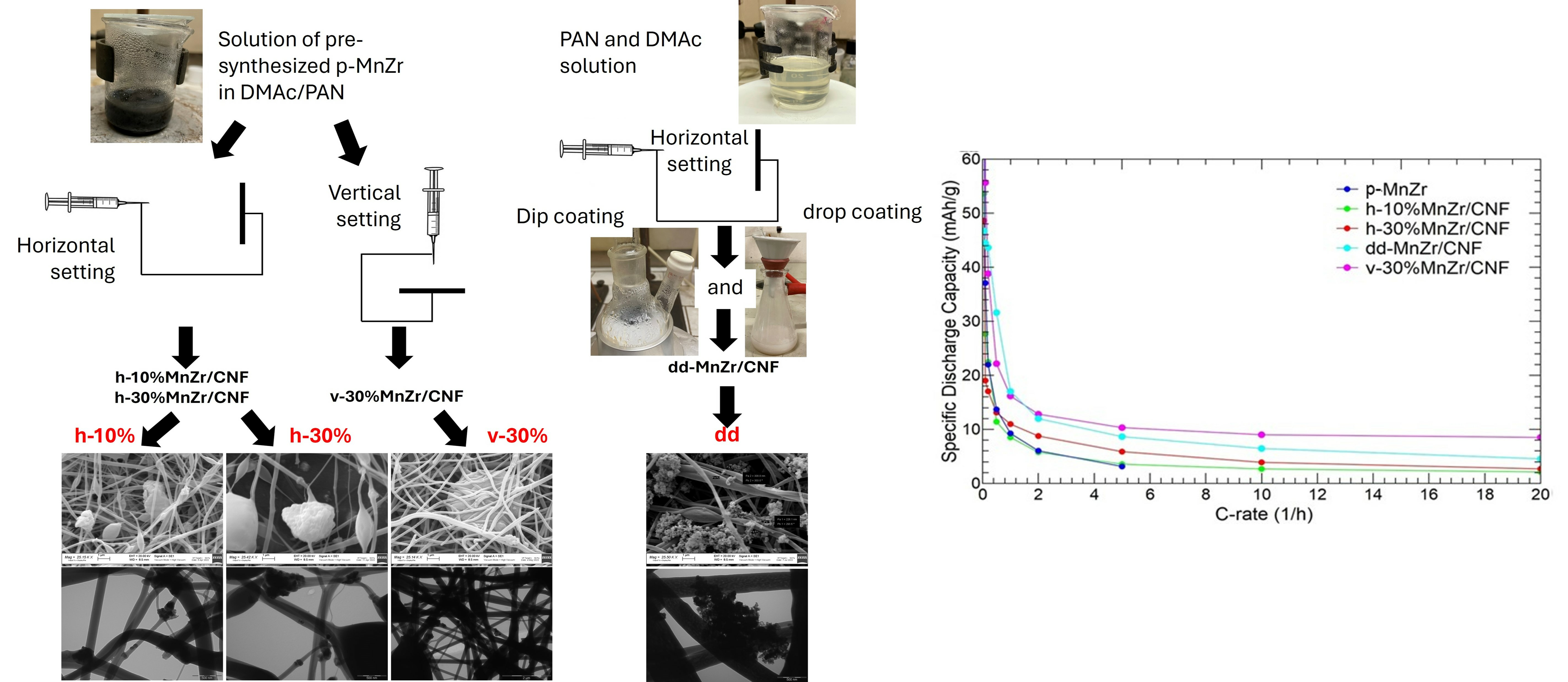
| CNF | Pure carbon nanofibers | Electrospinning Setting: horizontal |
| p-MnZr | Pristine Na3MnZr(PO4)3 powder | Sol–gel route |
| dd-MnZr/CNF | Self-standing cathode 33 wt% active material (from TGA) | Electrospinning Dip–drop method Setting: horizontal |
| h-10%MnZr/CNF | Self-standing cathode 10 wt% active material (from synthesis) | Electrospinning Active material dispersion Setting: horizontal |
| h-30%MnZr/CNF | Self-standing cathode 30 wt% active material (from synthesis) | Electrospinning Active material dispersion Setting: horizontal |
| v-30%MnZr/CNF | Self-standing cathode 30 wt% active material (from synthesis) | Electrospinning Active material dispersion Setting: vertical |
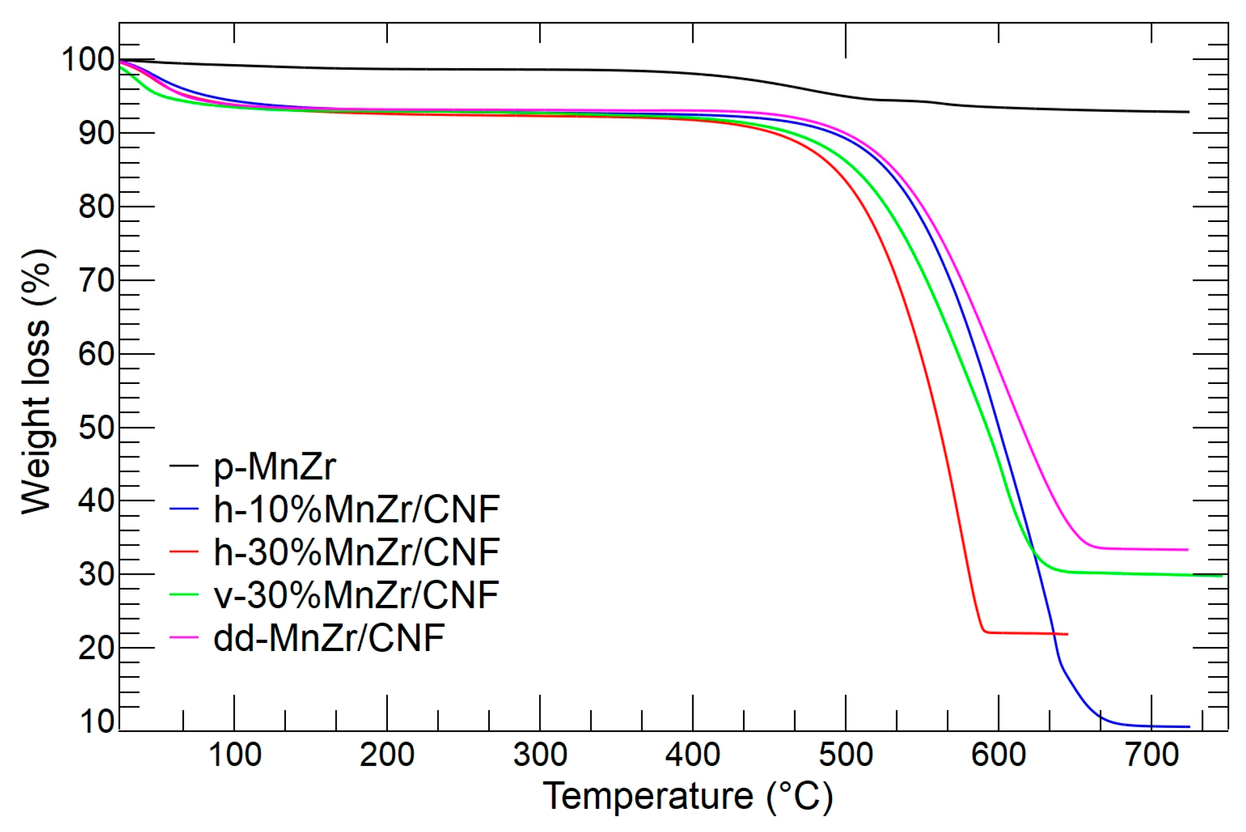
| SAMPLE | RESIDUAL MASS (wt%) |
|---|---|
| h-10%MnZr/CNF | 9.3 |
| h-30%MnZr/CNF | 21.8 |
| v-30%MnZr/CNF | 29.8 |
| dd-MnZr/CNF | 33.3 |
Disclaimer/Publisher’s Note: The statements, opinions and data contained in all publications are solely those of the individual author(s) and contributor(s) and not of MDPI and/or the editor(s). MDPI and/or the editor(s) disclaim responsibility for any injury to people or property resulting from any ideas, methods, instructions or products referred to in the content. |
© 2024 by the authors. Licensee MDPI, Basel, Switzerland. This article is an open access article distributed under the terms and conditions of the Creative Commons Attribution (CC BY) license (https://creativecommons.org/licenses/by/4.0/).
Share and Cite
Conti, D.M.; Urru, C.; Bruni, G.; Galinetto, P.; Albini, B.; Milanese, C.; Pisani, S.; Berbenni, V.; Capsoni, D. Design of Na3MnZr(PO4)3/Carbon Nanofiber Free-Standing Cathodes for Sodium-Ion Batteries with Enhanced Electrochemical Performances through Different Electrospinning Approaches. Molecules 2024, 29, 1885. https://doi.org/10.3390/molecules29081885
Conti DM, Urru C, Bruni G, Galinetto P, Albini B, Milanese C, Pisani S, Berbenni V, Capsoni D. Design of Na3MnZr(PO4)3/Carbon Nanofiber Free-Standing Cathodes for Sodium-Ion Batteries with Enhanced Electrochemical Performances through Different Electrospinning Approaches. Molecules. 2024; 29(8):1885. https://doi.org/10.3390/molecules29081885
Chicago/Turabian StyleConti, Debora Maria, Claudia Urru, Giovanna Bruni, Pietro Galinetto, Benedetta Albini, Chiara Milanese, Silvia Pisani, Vittorio Berbenni, and Doretta Capsoni. 2024. "Design of Na3MnZr(PO4)3/Carbon Nanofiber Free-Standing Cathodes for Sodium-Ion Batteries with Enhanced Electrochemical Performances through Different Electrospinning Approaches" Molecules 29, no. 8: 1885. https://doi.org/10.3390/molecules29081885
APA StyleConti, D. M., Urru, C., Bruni, G., Galinetto, P., Albini, B., Milanese, C., Pisani, S., Berbenni, V., & Capsoni, D. (2024). Design of Na3MnZr(PO4)3/Carbon Nanofiber Free-Standing Cathodes for Sodium-Ion Batteries with Enhanced Electrochemical Performances through Different Electrospinning Approaches. Molecules, 29(8), 1885. https://doi.org/10.3390/molecules29081885