
Nanosecond Laser Induced Surface Structuring of Cadmium after Ablation in Air and Propanol Ambient
 ,
,
Abstract
:1. Introduction
2. Experimental Setup
3. Results and Discussions
3.1. Analytical Evaluation of Laser Fluence along with Thermal Diffusivity and Ablation Threshold
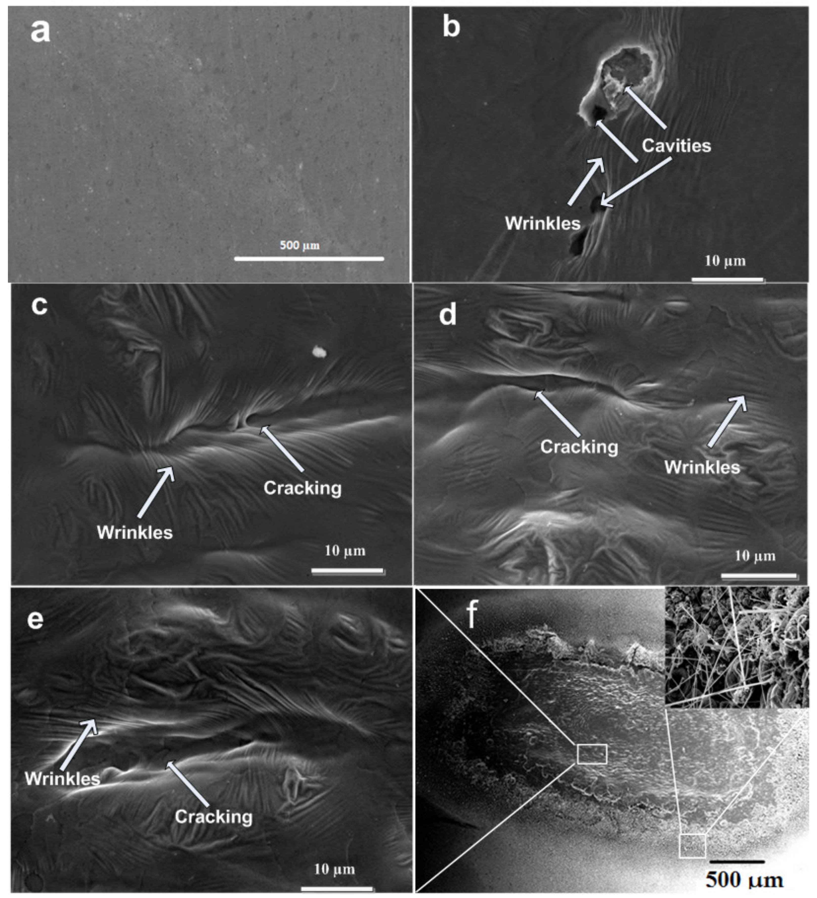
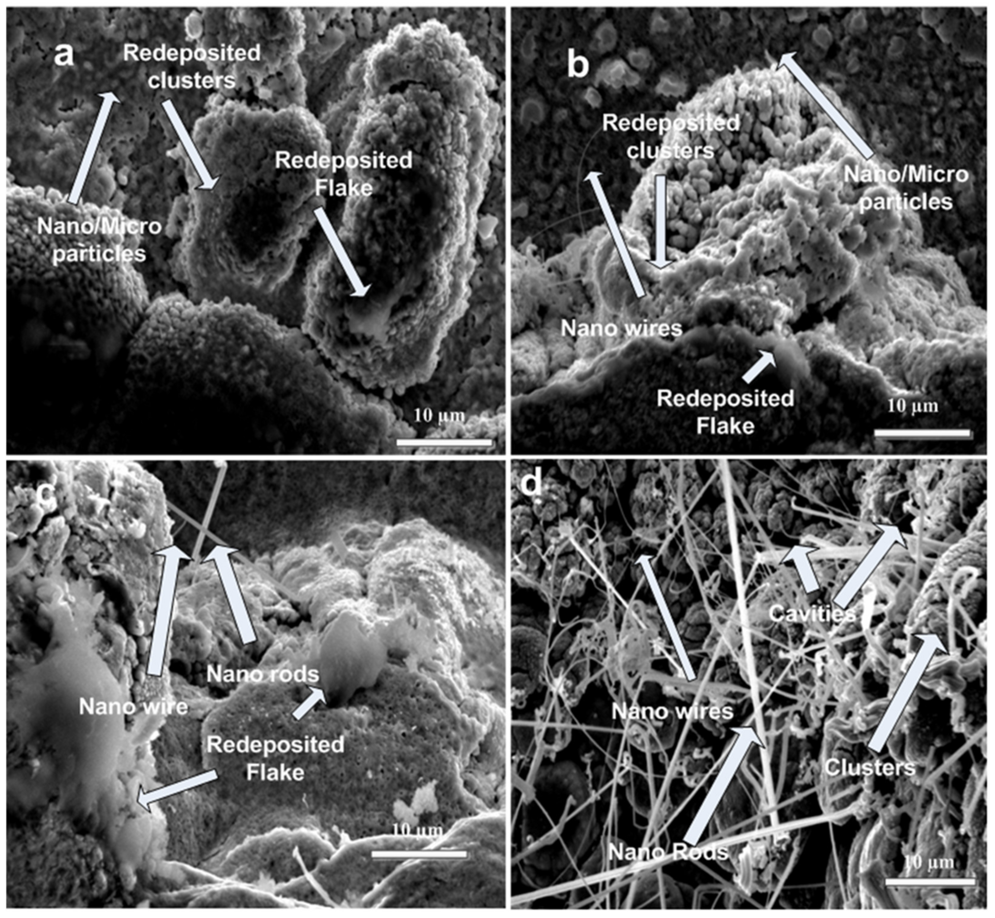
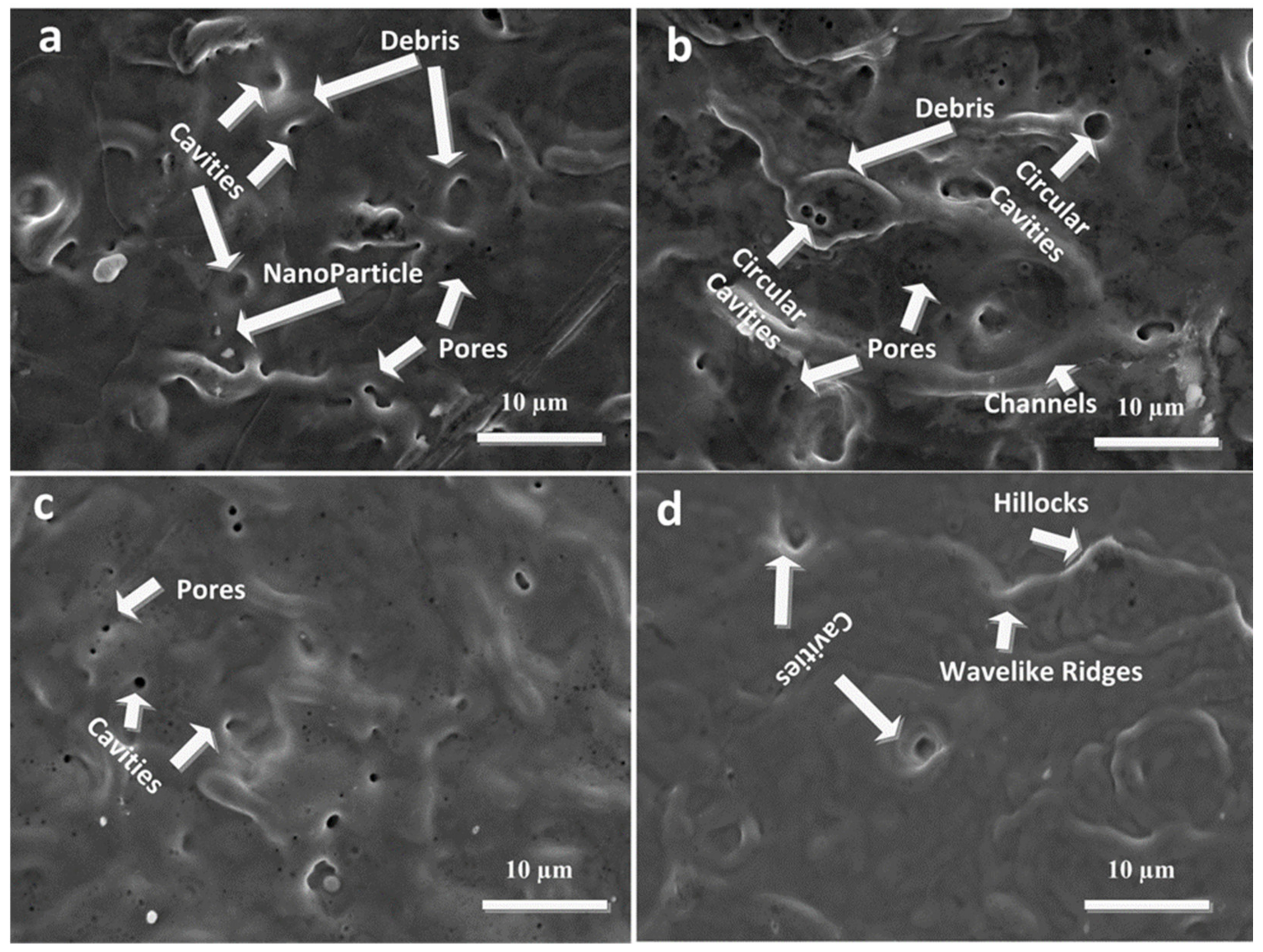
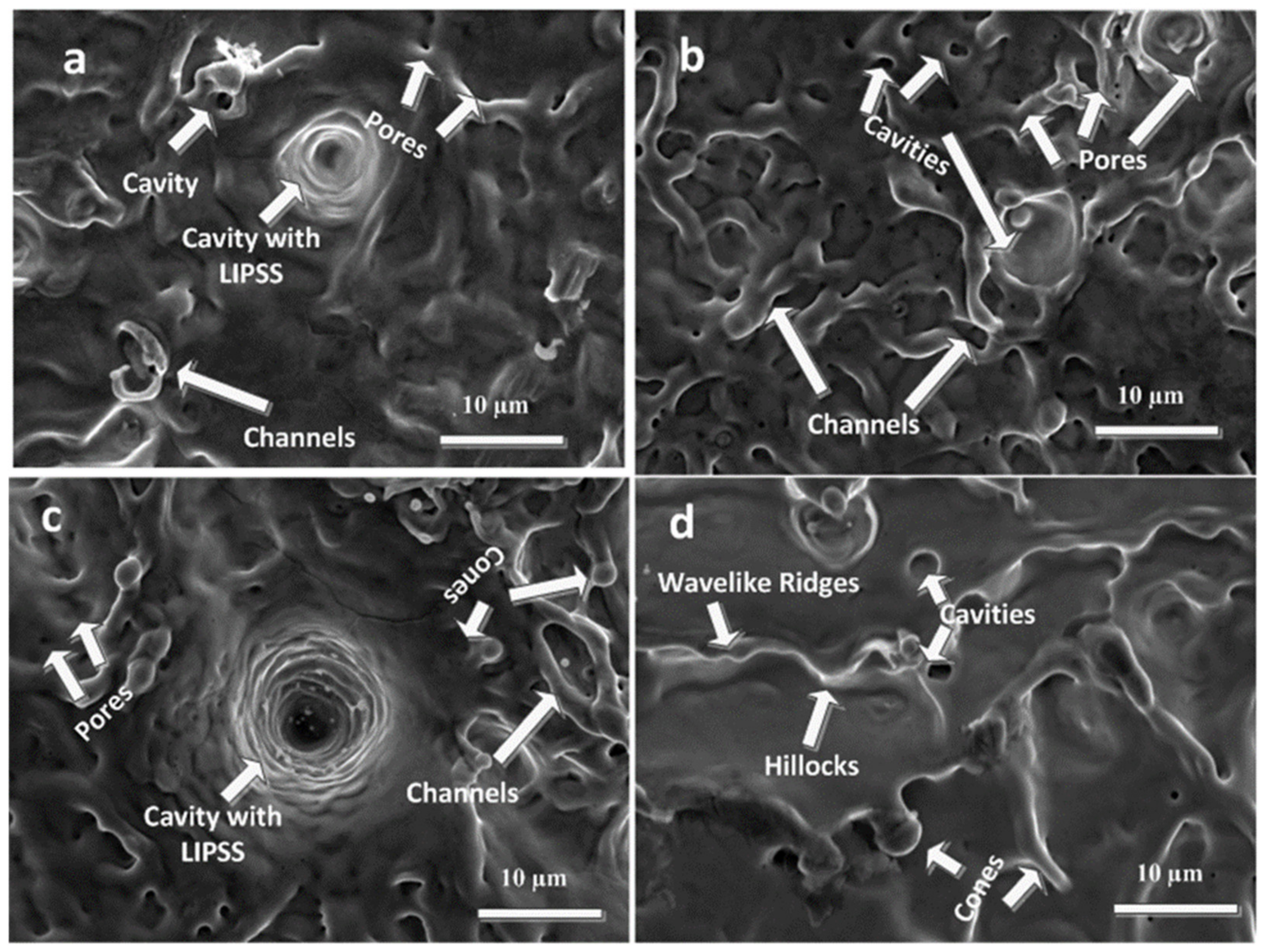
3.2. SEM Analysis
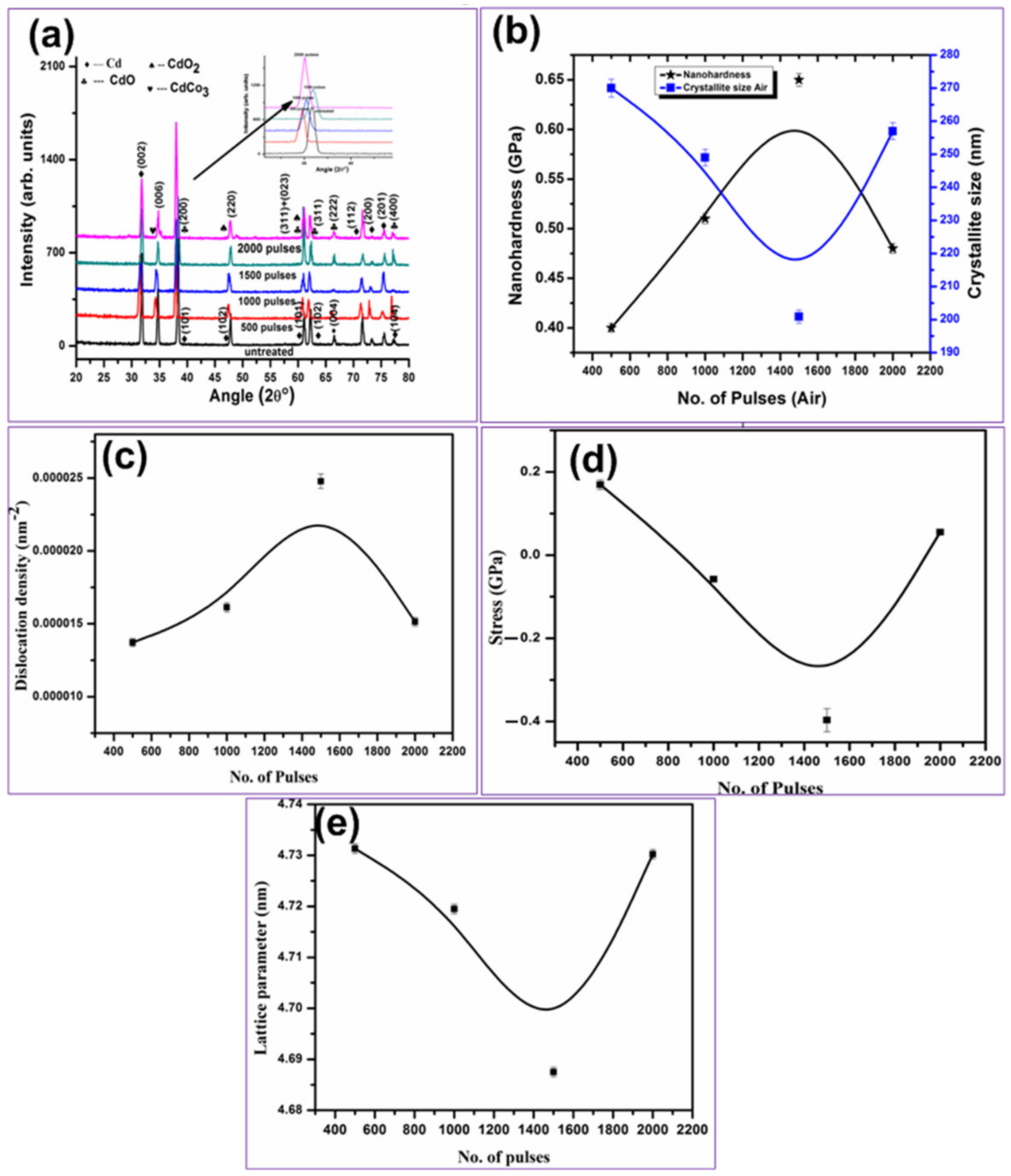
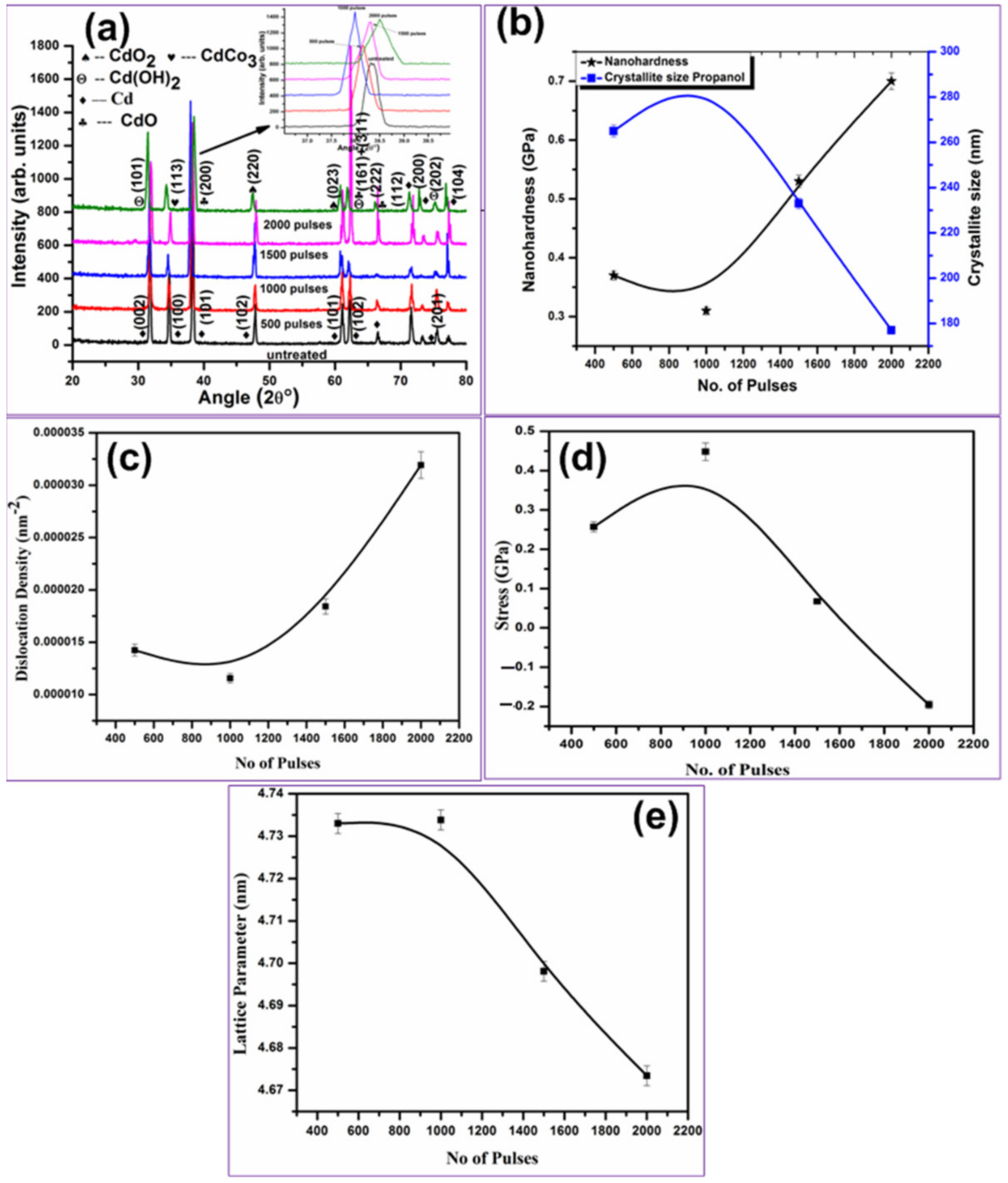
3.3. XRD Analysis
3.4. Hardness Analysis
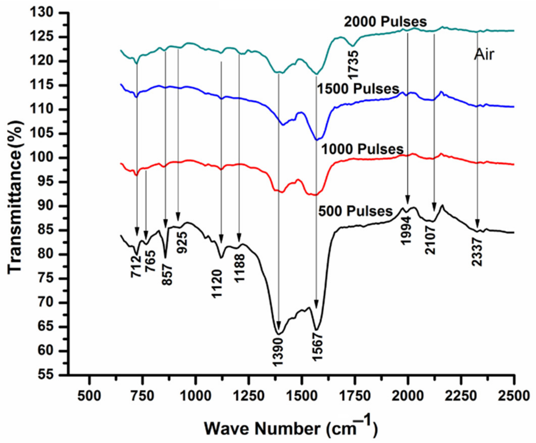
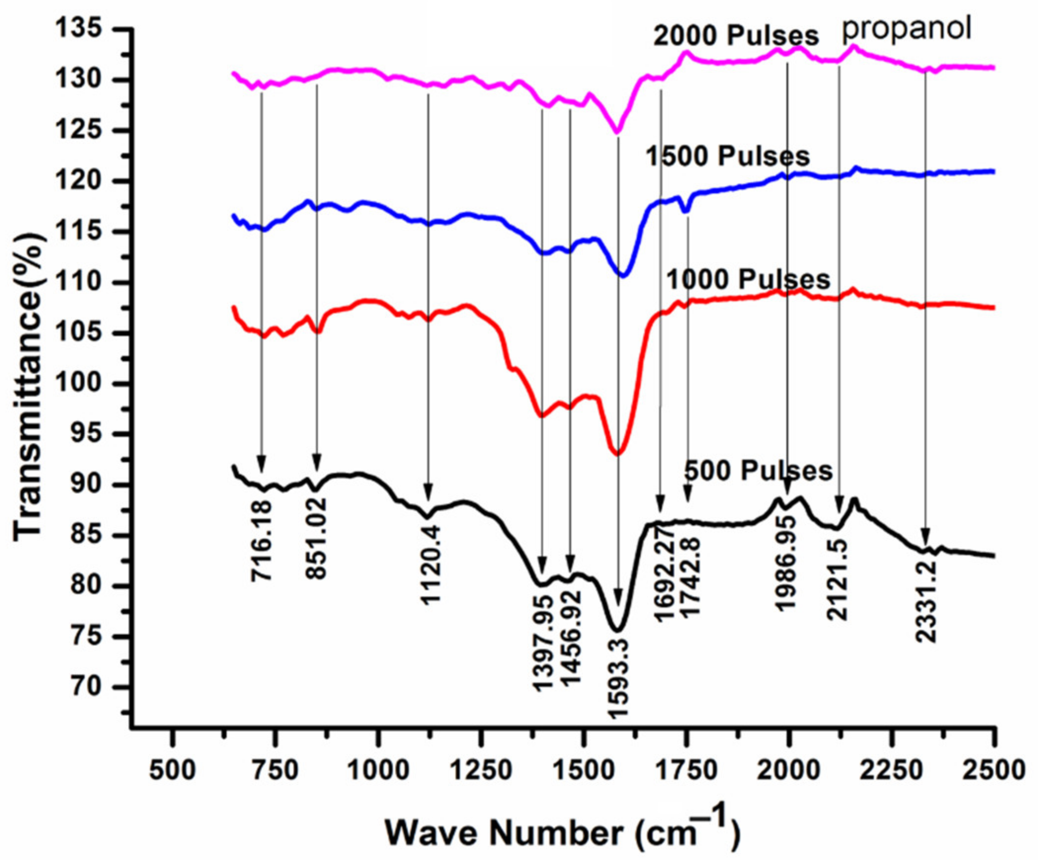
3.5. FTIR Analysis
3.6. EDS Analysis
4. Conclusions
Author Contributions
Funding
Institutional Review Board Statement
Informed Consent Statement
Data Availability Statement
Conflicts of Interest
References
- Ryu, J.-H.; Yang, J.-H.; Yoh, J.J. Novel utilization of the molecular band signal in metal oxides: Understanding the aging process of pyrotechnic substances by using laser induced plasma emissions. Opt. Mater. Express 2019, 9, 410–422. [Google Scholar] [CrossRef]
- Nancy, P.; James, J.; Valluvadasan, S.; Kumar, R.A.; Kalarikkal, N. Laser–plasma driven green synthesis of size controlled silver nanoparticles in ambient liquid. Nano-Struct. Nano-Objects 2018, 16, 337–346. [Google Scholar] [CrossRef]
- Yuan, G.; Liu, Y.; Ngo, C.-V.; Guo, C. Rapid fabrication of anti-corrosion and self-healing superhydrophobic aluminum surfaces through environmentally friendly femtosecond laser processing. Opt. Express 2020, 28, 35636–35650. [Google Scholar] [CrossRef] [PubMed]
- Aragón, C.; Aguilera, J. Characterization of laser induced plasmas by optical emission spectroscopy: A review of experiments and methods. Spectrochim. Acta Part B At. Spectrosc. 2008, 63, 893–916. [Google Scholar] [CrossRef]
- Baumann, R.; Milles, S.; Leupolt, B.; Kleber, S.; Dahms, J.; Lasagni, A.F. Tailored wetting of copper using precise nanosecond direct laser interference patterning. Opt. Lasers Eng. 2020, 137, 106364. [Google Scholar] [CrossRef]
- Zeng, H.; Du, X.-W.; Singh, S.C.; Kulinich, S.A.; Yang, S.; He, J.; Cai, W. Nanomaterials via Laser Ablation/Irradiation in Liquid: A Review. Adv. Funct. Mater. 2012, 22, 1333–1353. [Google Scholar] [CrossRef]
- Akhtar, S.; Rehman, S.; Mousa, S.; Firdos, A.; Khan, A.; Baig, U.; Saeed, A.; Gond, H.M.A. Evaluation of bioactivities of zinc oxide, cadmium sulfide and cadmium sulfide loaded zinc oxide nanostructured materials prepared by nanosecond pulsed laser. Mater. Sci. Eng. C 2020, 116, 111156. [Google Scholar] [CrossRef] [PubMed]
- Nadarajah, R.; Barcikowski, S.; Gökce, B. Picosecond laser-induced surface structures on alloys in liquids and their influence on nanoparticle productivity during laser ablation. Opt. Express 2020, 28, 2909–2924. [Google Scholar] [CrossRef] [PubMed]
- Adnan, J.; Arfan, M.; Shahid, T.; Khan, M.Z.; Masab, R.; Ramish, A.H.; Ahtasham, S.; Wattoo, A.G.; Hashim, M.; Zahoor, A.; et al. Synthesis of cadmium hydroxide nanostructure via compositehydroxide-mediated approach. Nanomat. Nanotechnol. 2019, 9, 1847980419852551. [Google Scholar] [CrossRef]
- Ismail, R.A.; Al-Samarai, A.M.E.; Mohmed, S.J.; Ahmed, H.H. Characteristics of nanostructured cdo/si heterojunction photodetector synthesized by cbd. Solid-State Electron. 2013, 82, 115–121. [Google Scholar] [CrossRef]
- Ferro, R.; Rodrı́guez, J.A. Influence of f-doping on the transmittance and electron affinity of CdO thin films suitable for solar cells technology. Sol. Energy Mater. Sol. Cells 2000, 64, 363–370. [Google Scholar] [CrossRef]
- Taufik, A.; Tju, H.; Prakoso, S.P.; Saleh, R. Different routes of synthesized cdo nanoparticles through microwave-assisted methods and photocatalytic study. AIP Confer. Proc. 2018, 2023, 020035. [Google Scholar]
- Srivastav, A.K.; Pandey, S.; Sood, K.N.; Halder, S.K.; Kishore, R. Novel growth morphologies of nano- and micro-structured cadmium oxide. Mater. Lett. 2008, 62, 727–730. [Google Scholar] [CrossRef]
- Ghoranneviss, P.; Dorranian, D.; Sari, A.H. Efects of laser fuence on the cd(oh)2/cdo nanostructures produced by pulsed laser ablation method. Opt. Quant. Electron. 2019, 51, 88. [Google Scholar] [CrossRef]
- Patil, P.P.; Phase, D.M.; Kulkarni, S.A.; Ghaisas, S.V.; Kulkarni, S.K.; Kanetkar, S.M.; Ogale, S.B.; Bhide, V.G. Pulsed-laser-induced reactive quenching at liquid-solid interface: Aqueous oxidation of iron. Phys. Rev. Lett. 1987, 58, 238–241. [Google Scholar] [CrossRef] [PubMed]
- Sasaki, T.; Shimizu, Y.; Koshizaki, N. Preparation of metal oxide-based nanomaterials using nanosecond pulsed laser ablation in liquids. J. Photochem. Photobio. A Chem. 2006, 182, 335–341. [Google Scholar] [CrossRef]
- Turkevich, J.; Stevenson, P.C.; Hillier, J. A study of the nucleation and growth processes in the synthesis of colloidal gold. Discuss. Faraday Soc. 1951, 11, 55–75. [Google Scholar] [CrossRef]
- Brust, M.; Walker, M.; Bethell, D.; Schiffrin, D.J.; Whyman, R. Synthesis of thiol-derivatised gold nanoparticles in a two-phase liquid-liquid system. J.Chem. Soc. Chem. Commun. 1994, 7, 801–802. [Google Scholar] [CrossRef]
- Mostafa, A.M.; Yousef, S.A.; Eisa, W.H.; Ewaida, M.A.; Al-Ashkar, E.A. Synthesis of cadmium oxide nanoparticles by pulsed laser ablation in liquid environment. Optik 2017, 144, 679–684. [Google Scholar] [CrossRef]
- Barcikowski, S.; Hahn, A.; Kabashin, A.; Chichkov, B.N. Properties of nanoparticles generated during femtosecond laser machining in air and water. Appl. Phys. A 2007, 87, 47–55. [Google Scholar] [CrossRef]
- Pustovalov, V.K.; Smetannikov, A.S.; Zharov, V.P. Photothermal and accompanied phenomena of selective nanophotothermolysis with goldnanoparticles and laser pulses. Laser Phys. Lett. 2008, 5, 775–792. [Google Scholar] [CrossRef]
- Ali, N.; Bashir, S.; Kalsoom, U.-I.; Akram, M.; Mahmood, K. Effect of dry and wet ambient environment on the pulsed laser ablation of titanium. Appl. Surf. Sci. 2013, 270, 49–57. [Google Scholar] [CrossRef]
- Darwish, A.M.; Eisa, W.; Shabaka, A.A.; Talaat, H. Synthesis of Nano-Cadmium Sulfide by Pulsed Laser Ablation in Liquid Environment. Spectrosc. Lett. 2015, 48, 638. [Google Scholar] [CrossRef]
- Kalsoom, U.I.; Ali, N.; Bashir, S.; Alshehri, A.; Begum, N. Study of Micro/Nano Structuring and Mechanical Properties of KrF Excimer Laser Irradiated Al for Aerospace Industry and Surface Engineering Applications. Materials 2021, 14, 3671. [Google Scholar] [CrossRef]
- Suhail, M.H.; Ibrahim, I.M.; Rao, G.M. Characterization and gas sensitivity of cadmium oxide thin films prepared by thermal evaporation technique. Int. J. Thin Film Sci. Technol. 2012, 1, 1–8. [Google Scholar]
- Le Drogoff, B.; Vidal, F.; Laville, S.; Chaker, M.; Johnston, T.; Barthélemy, O.; Margot, J.; Sabsabi, M. Laser-ablated volume and depth as a function of pulse duration in aluminum targets. Appl. Opt. 2005, 44, 278–281. [Google Scholar] [CrossRef]
- Deuzeman, M.J.; Stodolna, A.S.; Leerssen, E.E.B.; Antoncecchi, A.; Spook, N.; Kleijntjens, T.; Versluis, J.; Witte, S.; Eikema, K.S.E.; Ubachs, W.; et al. Ion distribution and ablation depth measurements of a fs-ps laser-irradiated solid tin target. J. Appl. Phys. 2017, 121, 103301. [Google Scholar] [CrossRef] [Green Version]
- Pronko, P.P.; Dutta, S.K.; Du, D.; Singh, R.K. Thermophysical effects in laser processing of materials with picosecond and femtosecond pulses. J. Appl. Phys. 1995, 78, 6233–6240. [Google Scholar] [CrossRef] [Green Version]
- Huang, H.; Yan, J. Laser Patterning of Metallic Glass; Springer: Berlin/Heidelberg, Germany, 2018; pp. 1–29. [Google Scholar]
- Pathanjali, V.D.G.A.; Srinivasan, N. Laser technique in diaphragm cum rupture disc for defence oriented silver oxide zinc reserve batteries. Mater. Manuf. Proc. 2019, 34, 447–454. [Google Scholar]
- Truong, S.L.; Levi, G.; Bozon-Verduraz, F.; Petrovskaya, A.; Simakin, A.; Shafeev, G. Generation of nanospikes via laser ablation of metals in liquid environment and their activity in surface-enhanced Raman scattering of organic molecules. Appl. Surf. Sci. 2007, 254, 1236–1239. [Google Scholar] [CrossRef]
- Francesco, B. Synthesis of Zno-Based Nanostructured Materials via Pulsed Laser Ablation in Liquid. Master’s Thesis, School of Industrial and Informat ion Engineering, Milano, Italy, 2015. [Google Scholar]
- Zhang, X.; Zeng, H.; Cai, W. Laser power effect on morphology and photoluminescence of ZnO nanostructures by laser ablation in water. Mater. Lett. 2009, 63, 191–193. [Google Scholar] [CrossRef]
- Scholz, T.; Dickmann, K. Investigation on particle formation during laser ablation process with high brilliant radiation. Phys. Procedia 2010, 5, 311–316. [Google Scholar] [CrossRef] [Green Version]
- Tillack, M.S.; Blair, D.W.; Harilal, S.S. The effect of ionization on cluster formation in laser ablation plumes. Nanotechnology 2004, 15, 390–403. [Google Scholar] [CrossRef]
- Sajti, C.L.; Sattari, R.; Chichkov, B.N.; Barcikowski, S. Gram Scale Synthesis of Pure Ceramic Nanoparticles by Laser Ablation in Liquid. J. Phys. Chem. C 2010, 114, 2421–2427. [Google Scholar] [CrossRef]
- Ma, S.; Deng, J.; Xu, Y.; Tao, W.; Wang, X.; Lin, Z.; Zhang, Q.; Gu, L.; Zhong, W. Pollen-like self-supported FeIr alloy for improved hydrogen evolution reaction in acid electrolyte. J. Energy Chem. 2021, 66, 560–565. [Google Scholar] [CrossRef]
- Singh, R.K.; Narayan, J. Pulsed-laser evaporation technique for deposition of thin films: Physics and theoretical model. Phys. Rev. B 1990, 41, 8843–8859. [Google Scholar] [CrossRef]
- Kelly, R.; Miotello, A. Comments on explosivemechanisms of laser sputtering. Appl. Surf. Sci. 1996, 96–98, 205–215. [Google Scholar] [CrossRef]
- Bulgakova, N.M.; Evtushenko, A.B.; Shukhov, Y.G.; Kudryashov, S.I.; Bulgakov, A.V. Role of laser-induced plasma in ultradeep drilling of materials by nanosecond laser pulses. Appl. Surf. Sci. 2011, 257, 10876–10882. [Google Scholar] [CrossRef]
- Morales, A.M.; Lieber, C.M. A Laser Ablation Method for the Synthesis of Crystalline Semiconductor Nanowires. Science 1998, 279, 208–211. [Google Scholar] [CrossRef]
- Li, L.; Hong, M.; Schmidt, M.; Zhong, M.; Malshe, A.; In’Tveld, B.H.; Kovalenko, V. Laser nano-manufacturing–State of the art and challenges. CIRP Ann. 2011, 60, 735–755. [Google Scholar] [CrossRef]
- Grynko, D.A.; Fedoryak, A.N.; Dimitriev, O.P.; Lin, A.; Laghumavarapu, R.B.; Huffaker, D.L. Growth of cds nanowire crystals: Vapor–liquid–solid versus vapor–solid mechanisms. Surf. Coat. Technol. 2013, 230, 234–238. [Google Scholar] [CrossRef]
- Simakin, A.; Voronov, V.; Kirichenko, N.; Shafeev, G. Nanoparticles produced by laser ablation of solids in liquid environment. Appl. Phys. A 2004, 79, 1127–1132. [Google Scholar] [CrossRef]
- Bulgakova, N.M.; Bulgakov, A.V. Pulsed laser ablation of solids: Transition fromnormal vaporization to phase explosion. Appl. Phys. A Mater. Sci. Process. 2001, 73, 199–208. [Google Scholar] [CrossRef]
- Choo, K.L.; Ogawa, Y.; Kanbargi, G.; Otra, V.; Raff, L.M.; Komanduri, R. Micromachining of si by short pulse laser ablation in air and under water. Mater. Sci. Eng. A 2004, 372, 145–162. [Google Scholar] [CrossRef]
- Amer, M.S.; Dosser, L.; LeClair, S.; Maguire, J.F. Induced stresses and structural changes in silicon wafers as a result of laser micro-machining. Appl. Surf. Sci. 2002, 187, 291–296. [Google Scholar] [CrossRef]
- Emel’Yanov, V.; Babak, D. Defect capture under rapid solidification of the melt induced by the action of femtosecond laser pulses and formation of periodic surface structures on a semiconductor surface. Appl. Phys. A 2002, 74, 797–805. [Google Scholar] [CrossRef]
- Wu, Y.; Xu, K.; Zhang, Z.; Shuai, X.D.; Hao, Y.; Jian, Z.; Liu, G.Y. Effect of laser irradiation on the electrodeposition process, mechanical and corrosion properties of an amorphous ni-p coating. Surf. Coat. Technol. 2022, 429, 127961. [Google Scholar] [CrossRef]
- Karimzadeh, R.; Anvari, J.Z.; Mansour, N. Nanosecond pulsed laser ablation of silicon in liquids. Appl. Phys. A 2008, 94, 949–955. [Google Scholar] [CrossRef]
- Kalsoom, U.I.; Bashir, S.; Ali, N. SEM, AFM, EDX and XRD analysis of laser ablated Ti in nonreactive and reactive ambient environments. Surf. Coat. Technol. 2013, 235, 297–302. [Google Scholar] [CrossRef]
- Baladi, A.; Mamoory, R.S. Investigation of different liquid media and ablation times on pulsed laser ablation synthesis of aluminum nanoparticles. Appl. Surf. Sci. 2010, 256, 7559–7564. [Google Scholar] [CrossRef]
- Simões, J.; Riva, R.; Miyakawa, W. High-speed Laser-Induced Periodic Surface Structures (LIPSS) generation on stainless steel surface using a nanosecond pulsed laser. Surf. Coat. Technol. 2018, 344, 423–432. [Google Scholar] [CrossRef]
- Bashir, S.; Rafique, M.S.; Husinsky, W. Femtosecond laser-induced subwavelength riplpes on Al, Si, CaF2 and cr-39. Nucl. Instrum. Methods Phys. Res. Sect. B 2012, 275, 1–6. [Google Scholar] [CrossRef]
- Shen, M.Y.; Crouch, C.H.; Carey, J.E.; Mazur, E. Femtosecond laser-induced formation of submicrometer spikes on silicon in water. Appl. Phys. Lett. 2004, 85, 5694–5696. [Google Scholar] [CrossRef]
- Kang, H.W.; Lee, H.; Welch, A.J. Laser ablation in a liquid-confined environment using a nanosecond laser pulse. J. Appl. Phys. 2008, 103, 083101. [Google Scholar] [CrossRef]
- Popok, V.N.; Prasalovich, S.V.; Samuelsson, M.; Campbell, E.E.B. Design and capabilities of a cluster implantation and deposition apparatus: First results on hillock formation under energetic cluster ion bombardment. Rev. Sci. Instrum. 2002, 73, 4283–4287. [Google Scholar] [CrossRef]
- Barmina, E.V.; Barberoglu, M.; Zorba, V.; Simakin, A.V.; Stratakis, E.; Fotakis, K.; Shafeev, G.A. Surface nanotexturing of tantalum by laser ablation in water. Quantum Electron. 2009, 39, 89–93. [Google Scholar] [CrossRef]
- Chrisey, D.B.; Hubler, K.G. Pulsed Laser Deposition of Thin Films; John Wiley & Son. Inc: Hoboken, NJ, USA, 1996. [Google Scholar]
- Shanmugam, N.; Saravanan, B.; Reagan, R.; Kannadasan, N.; Sathishkumar, K.; Cholan, S. Effect of thermal annealing on the Cd(oH)2 and preparation of CdO nanocrystals. Mod. Chem. Appl. 2014, 2, 1–5. [Google Scholar] [CrossRef] [Green Version]
- Cullity, B.D. Elements of X-ray Diffraction; Addison-Wesley publishing Company, Inc.: London, UK, 1978. [Google Scholar]
- Venkatachalam, S.; Kumar, R.T.R.; Mangalaraj, D.; Narayandass, S.K.; Kim, K.; Junsin, Y. Optoelectronic properties of zn0.52se 0.48/si schottky diodes. Solid-State Electr. 2004, 48, 2004–2219. [Google Scholar] [CrossRef]
- Khan, I.; Hassan, M.; Ahmad, R.; Qayyum, A.; Murtaza, G.; Zakaullah, M.; Rawat, R. Nitridation of zirconium using energetic ions from plasma focus device. Thin Solid Films 2008, 516, 8255–8263. [Google Scholar] [CrossRef]
- Khan, I.A.; Amna, N.; Kanwal, N.; Razzaq, M.; Farid, A.; Amin, N.; Ikhlaq, U.; Saleem, M.; Ahmad, R. Role of oxygen pressure on the structural, morphological and optical properties of C-Al2O3 films deposited by thermal evaporator. Mater. Res. Exp. 2017, 4, 036402–0364013. [Google Scholar] [CrossRef]
- Kalsoom, U.I.; Ali, N.; Bashir, S.; Alshehri, A.M.; Begum, N. Characterization of KrF Excimer Laser Ablation of Cadmium in Different Liquids for Biomedical and Industrial Applications. Coatings 2022, 12, 1193. [Google Scholar] [CrossRef]
- Anil, G.; Kumar, M.V.; Reddy, R.; Reddy, K.N. Growth of highly transparent and conductive CdO thin films deposited at different thicknesses by rf reactive magnetron sputtering. Mater. Res. Innov. 2015, 19, 204–211. [Google Scholar] [CrossRef]
- Özbek, Y.Y. Surface properties of AISI 4140 steel modified by pulse plasma technique. J. Mater. Res. Technol. 2019, 9, 2176–2185. [Google Scholar] [CrossRef]
- Hong, M.; Choi, S. Observation of changes in the metallurgical characteristics of Ni-Cr alloys using Nd:YAG laser welding. J. Dent. Biomech. 2014, 5, 1758736014547144. [Google Scholar] [CrossRef] [PubMed] [Green Version]
- Ali, N.; Umm-i-Kalsoom; Bashir, S.; Begum, N.; Ahmad, S.W. Surface, structural and mechanical properties of zirconium ablated by krf excimer laser radiation. Quant. Electron. 2016, 46, 1015–1022. [Google Scholar]
- Mostafa, A.; Hameed, M.; Obayya, S. Effect of laser shock peening on the hardness of AL-7075 alloy. J. King Saud Univ.-Sci. 2019, 31, 472–478. [Google Scholar] [CrossRef]
- Pacella, M.; Nekouie, V.; Badiee, A. Surface engineering of ultra-hard polycrystalline structures using a nanosecond Yb fibre laser: Effect of process parameters on microstructure, hardness and surface finish. J. Mater. Process. Technol. 2018, 266, 311–328. [Google Scholar] [CrossRef]
- Mwafya, E.A.; Mostafa, A.M. Multi walled carbon nanotube decorated cadmium oxide nanoparticles via pulsed laser ablation in liquid media. Opt. Laser Technol. 2019, 111, 249–254. [Google Scholar] [CrossRef]
- Bartosova, A.; Blinova, L.; Gerulovaresea, K. Research Papers Faculty of Materials Science And Technology in Trnavaslovak University of Technology in Bratislava. Charterisation of polyscacharides and lipids from selected greeen alga especies by ftir-atr spectroscopy. J. Slovak Univ. Technol. 2015, 23, 97–102. [Google Scholar]
- Wei, Z.; Jiao, D.; Xu, J. Using fourier transform infrared spectroscopy to study effects of magnetic field treatment on wheat (Triticum aestivum L.) seedlings. J. Spectrosc. 2015, 2015, 570190. [Google Scholar] [CrossRef] [Green Version]
- Ullah, R.; Ahmad, I.; Zhen, Y. Fourier transform infrared spectroscopy of (bisphenol A). J. Spectrosc. 2016, 2016, 5. [Google Scholar] [CrossRef] [Green Version]
- Munajad, A.; Subroto, C.; Suwarno. Fourier Transform Infrared (FTIR) Spectroscopy Analysis of Transformer Paper in Mineral Oil-Paper Composite Insulation under Accelerated Thermal Aging. Energies 2018, 11, 364. [Google Scholar] [CrossRef] [Green Version]
- Bandara, K.; Ekanayake, C.; Saha, T.K.; Annamalai, P.K. Understanding the ageing aspects of natural ester based insulation liquid in power transformer. IEEE Trans. Dielectr. Electr. Insul. 2016, 23, 246–257. [Google Scholar] [CrossRef]
- Prakash, T.; Arunkumar, T.; Raj, D.S.; Jayaprakash, R. Surfactant-liaised Variation in CdO Nanocomposites Morphology. Phys. Procedia 2013, 49, 36–43. [Google Scholar] [CrossRef] [Green Version]
- Bashir, S.; Vaheed, H.; Mahmood, K. Nanosecond pulsed laser ablation of brass in a dry andliquid-confined environment. Appl. Phys. A 2013, 110, 389–395. [Google Scholar] [CrossRef]
- Singh, S.C.; Swarnkar, R.K.; Gopal, R. Laser ablative approach for the synthesis of cadmiumhydroxide–oxide nanocomposite. J. Nanoparticle Res. 2009, 11, 1831–1838. [Google Scholar] [CrossRef]


| Number of Pulses (Air) | Diameter (µm) | Depth (µm) | Volume (103 µm3) |
|---|---|---|---|
| 500 | 1118.6 | 80 | 23.26 |
| 1000 | 1190 | 96 | 29.7 |
| 1500 | 1166.2 | 90 | 27.28 |
| 2000 | 1094 | 144 | 41.2 |
| Number of Pulses (Propanol) | Diameter (µm) | Depth (µm) | Volume (103 µm3) |
|---|---|---|---|
| 500 | 1237 | 73 | 23.47 |
| 1000 | 1309 | 100 | 35.73 |
| 1500 | 1190 | 120 | 37.43 |
| 2000 | 1047 | 102 | 27.76 |
| Number of Pulses (Air) | Average Intensity |
|---|---|
| 500 | 85 |
| 1000 | 94 |
| 1500 | 89.5 |
| 2000 | 88 |
| Number of Pulses (Propanol) | Average Intensity |
|---|---|
| 500 | 83 |
| 1000 | 90 |
| 1500 | 87 |
| 2000 | 85 |
| Element Name | Untreated | Air (Weight %) | Propanol (Weight %) |
|---|---|---|---|
| C | 1.18 | 0.45 | 4.1 |
| N | 1.33 | 1.7 | 3.28 |
| O | 3.34 | 20.9 | 15.22 |
| Al | 0.96 | -- | -- |
| Si | 0.11 | -- | -- |
| Cd | 90.36 | 75.45 | 75.20 |
| W | 0.23 | -- | -- |
| Pa | 2.49 | 1.5 | 2.2 |
Publisher’s Note: MDPI stays neutral with regard to jurisdictional claims in published maps and institutional affiliations. |
© 2022 by the authors. Licensee MDPI, Basel, Switzerland. This article is an open access article distributed under the terms and conditions of the Creative Commons Attribution (CC BY) license (https://creativecommons.org/licenses/by/4.0/).
Share and Cite
Umm-i-Kalsoom; Ali, N.; Bashir, S.; Akbar, S.; Rafique, M.S.; Alshehri, A.M.; Begum, N.; Iqbal, T.; Anwar, A. Nanosecond Laser Induced Surface Structuring of Cadmium after Ablation in Air and Propanol Ambient. Int. J. Mol. Sci. 2022, 23, 12749. https://doi.org/10.3390/ijms232112749
Umm-i-Kalsoom, Ali N, Bashir S, Akbar S, Rafique MS, Alshehri AM, Begum N, Iqbal T, Anwar A. Nanosecond Laser Induced Surface Structuring of Cadmium after Ablation in Air and Propanol Ambient. International Journal of Molecular Sciences. 2022; 23(21):12749. https://doi.org/10.3390/ijms232112749
Chicago/Turabian StyleUmm-i-Kalsoom, Nisar Ali, Shazia Bashir, Samina Akbar, Muhammad Shahid Rafique, Ali Mohammad Alshehri, Narjis Begum, Tanveer Iqbal, and Aneela Anwar. 2022. "Nanosecond Laser Induced Surface Structuring of Cadmium after Ablation in Air and Propanol Ambient" International Journal of Molecular Sciences 23, no. 21: 12749. https://doi.org/10.3390/ijms232112749