


The Tetrel Bond and Tetrel Halide Perovskite Semiconductors


Abstract

1. Introduction
2. Results
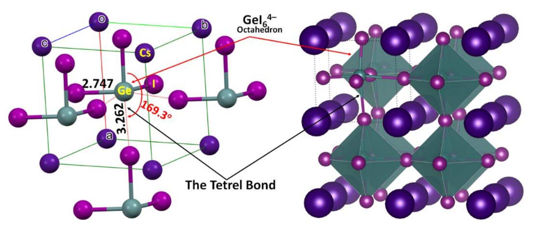
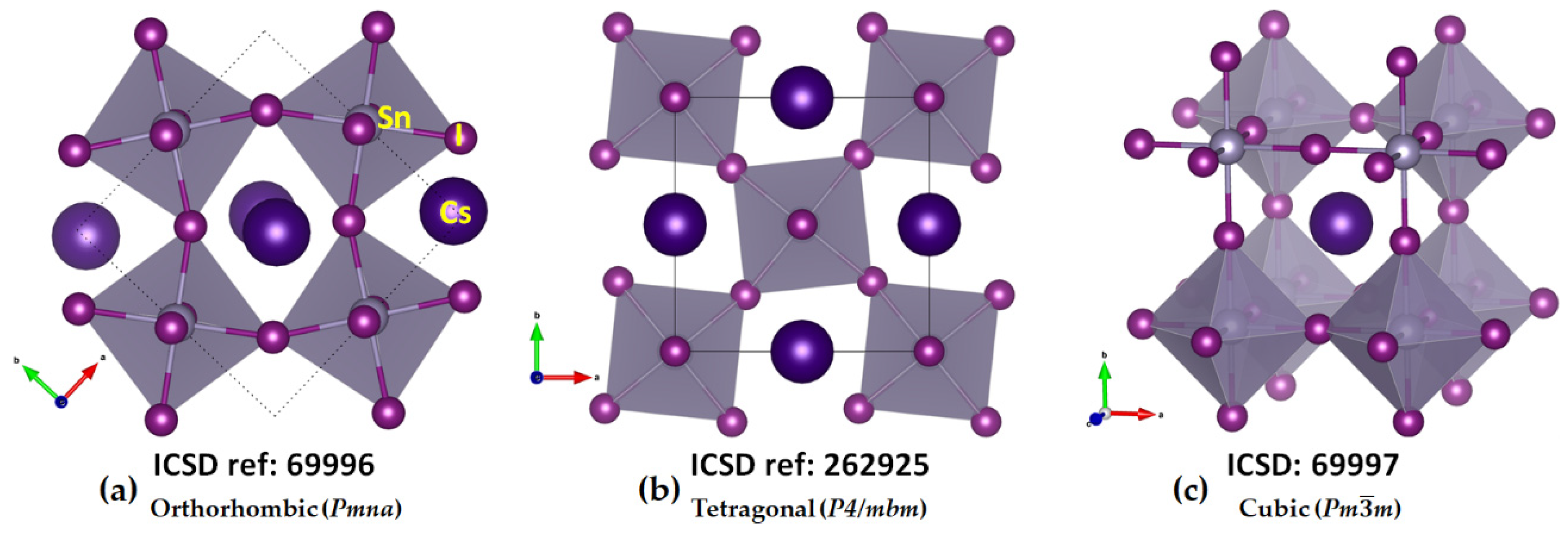
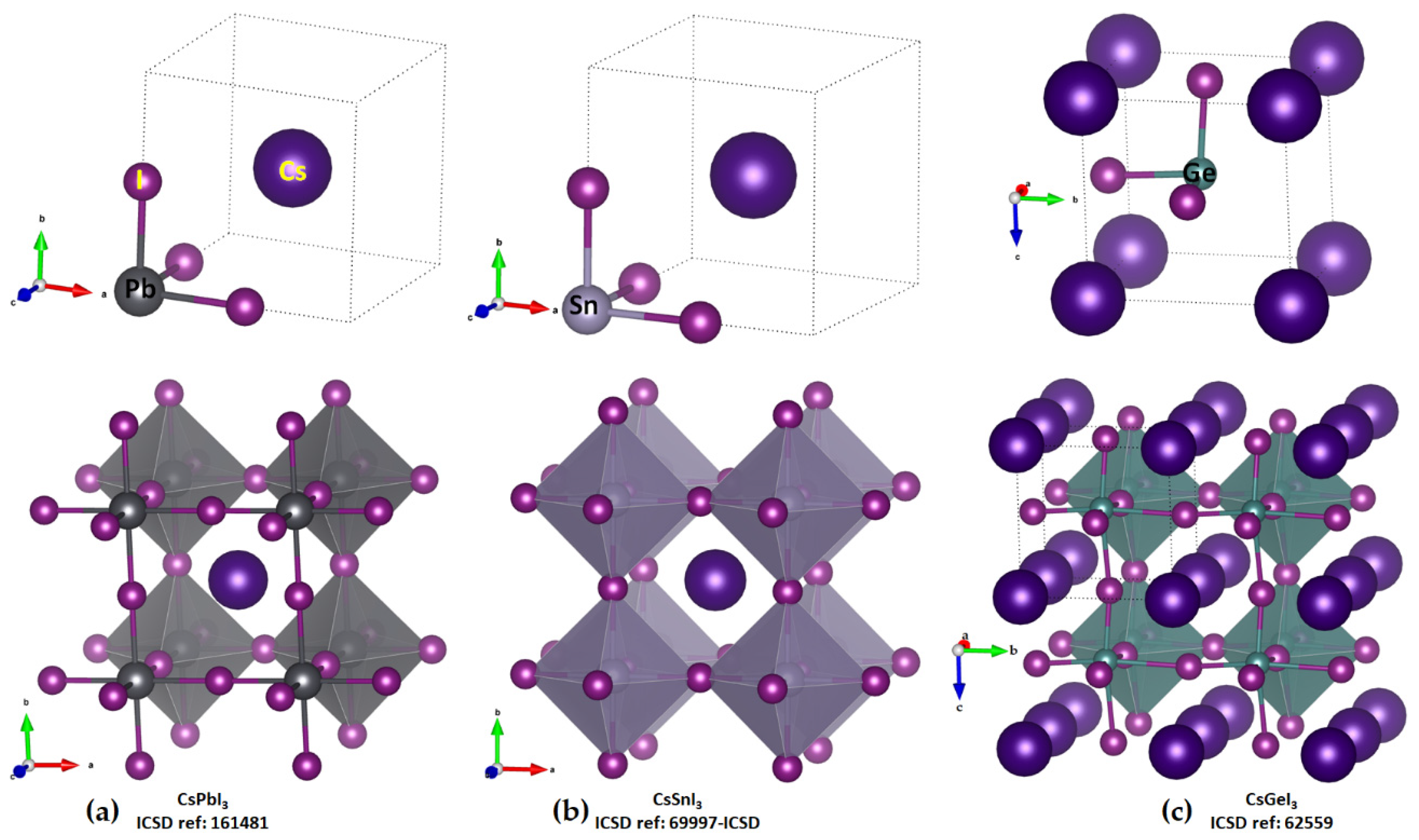
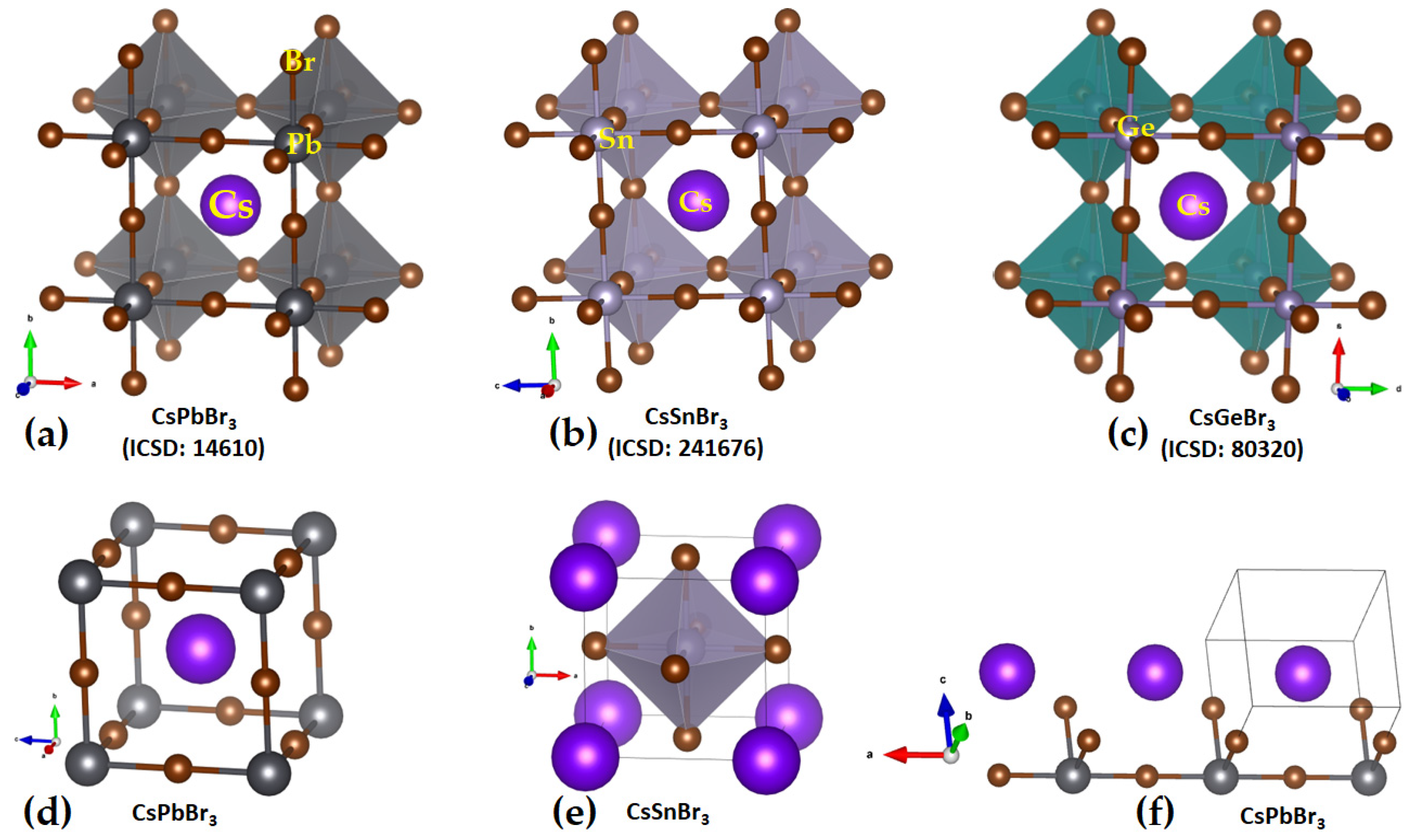
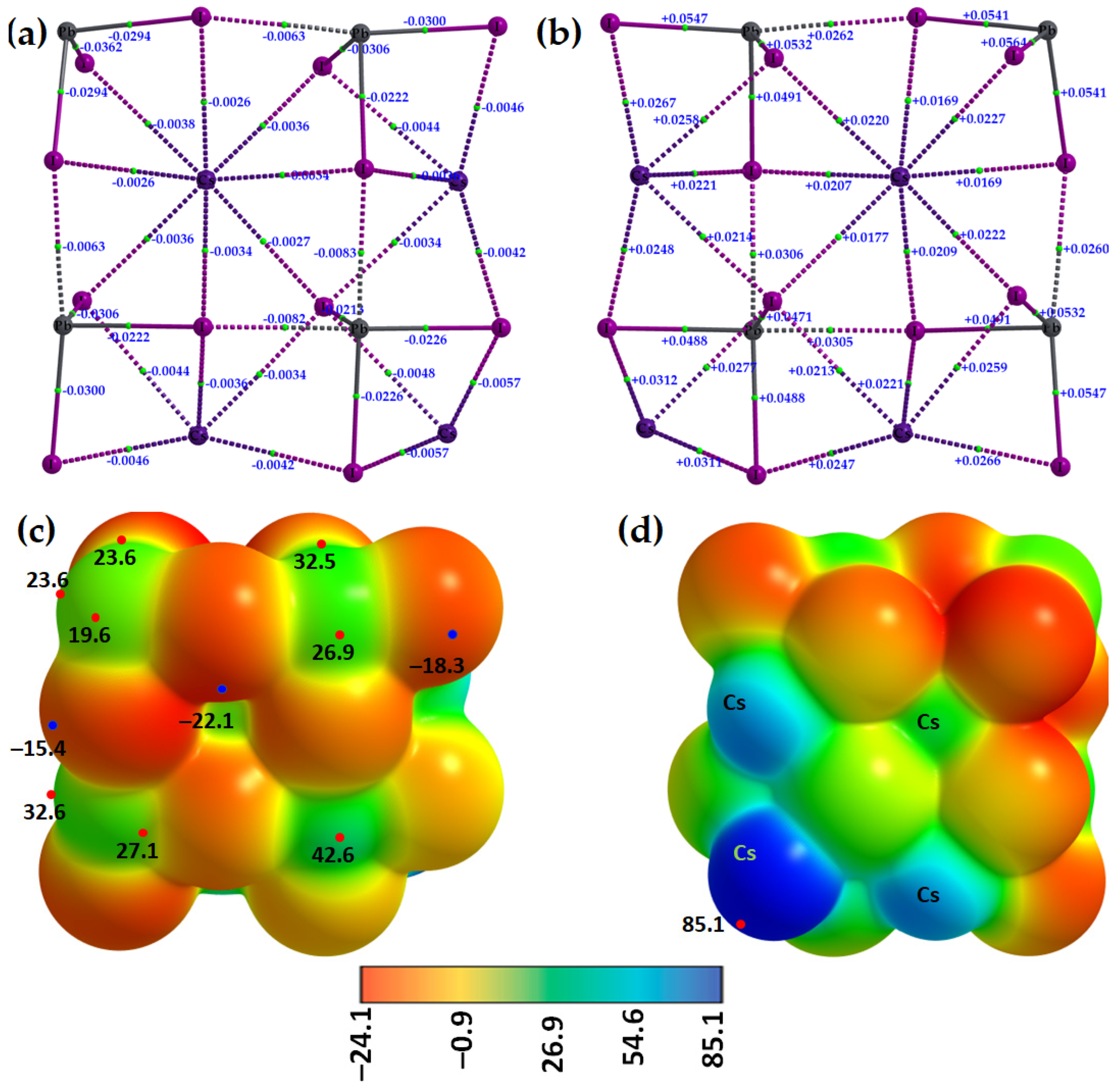
2.1. Illustrative Crystal Geometry of Cesium Tetrel Halide Perovskites
- (a)
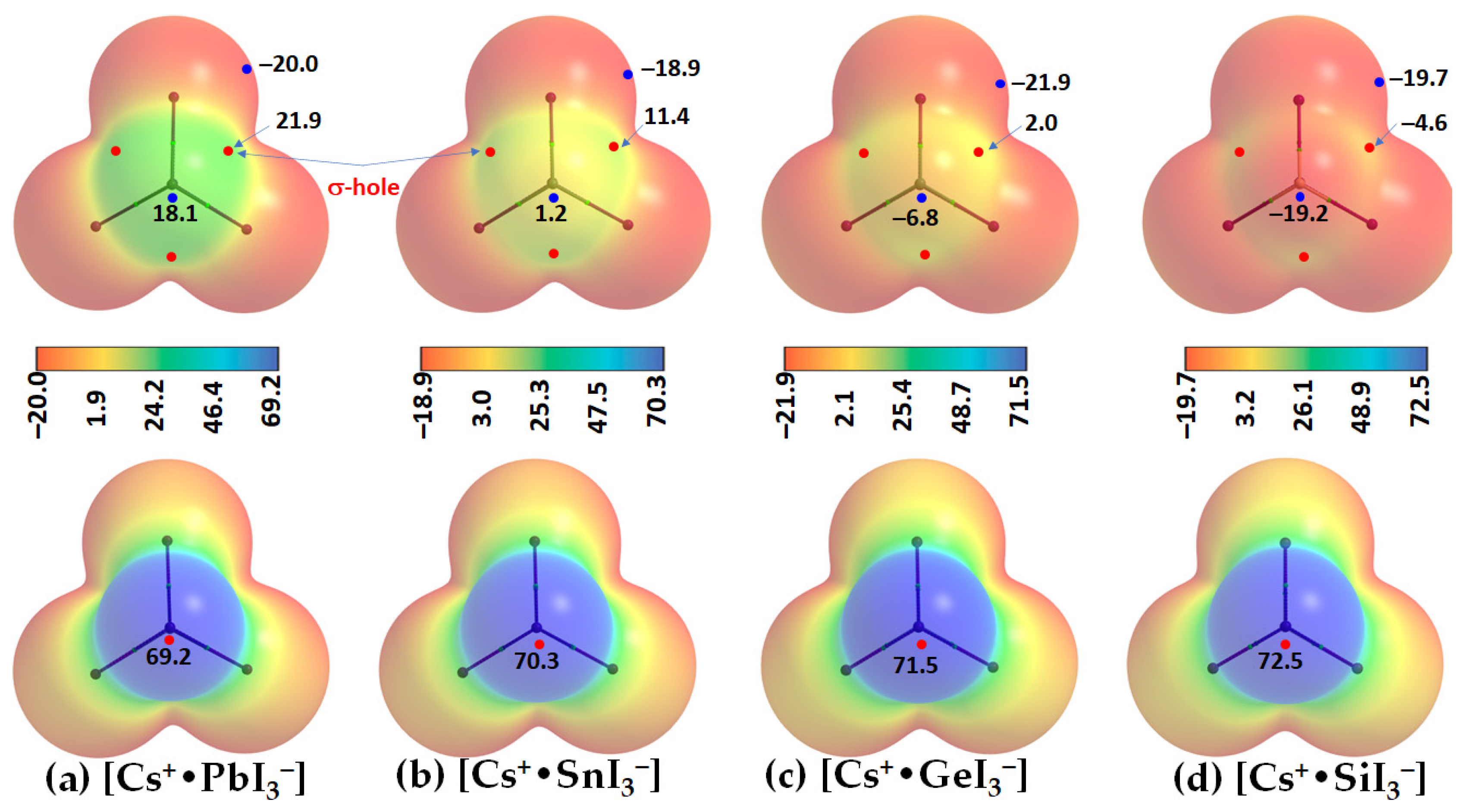
- Cesium Tetrel Iodide Perovskites
- (b)
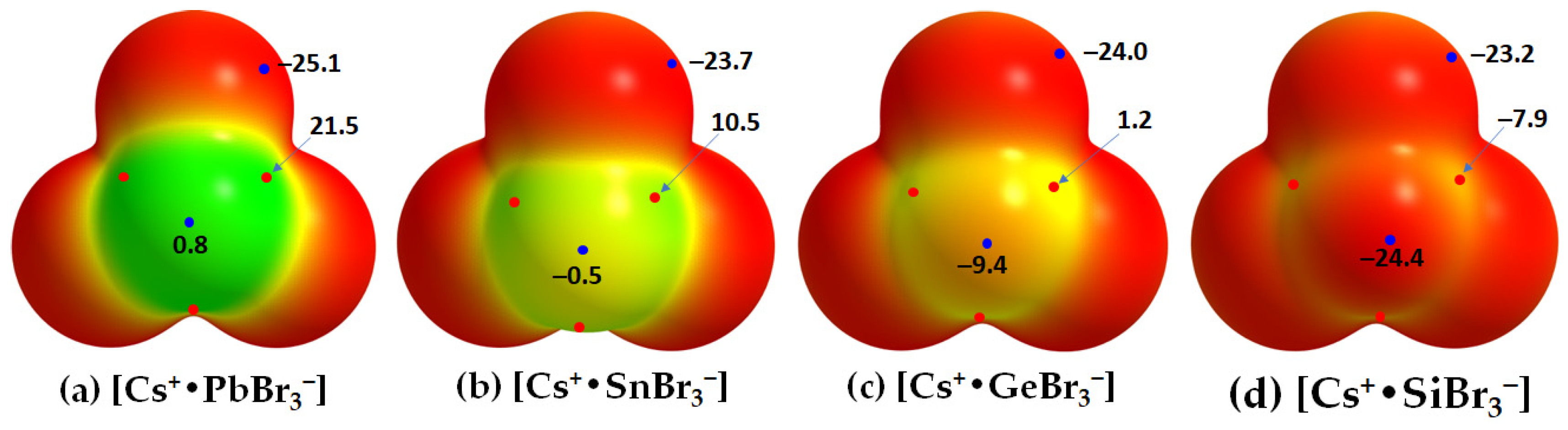
- Cesium Tetrel Bromide Perovskites
- (c)
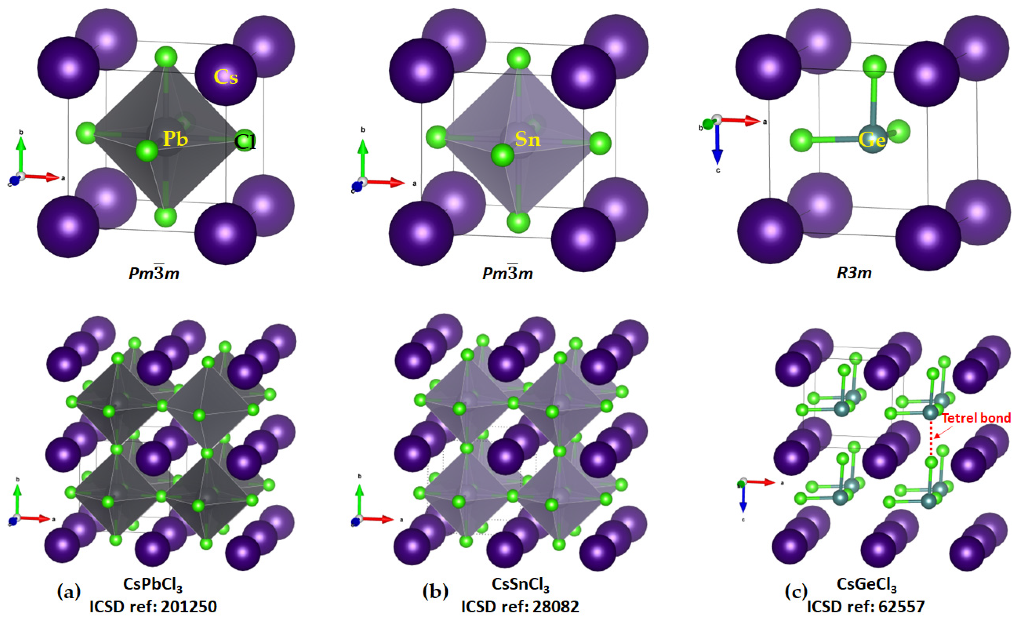
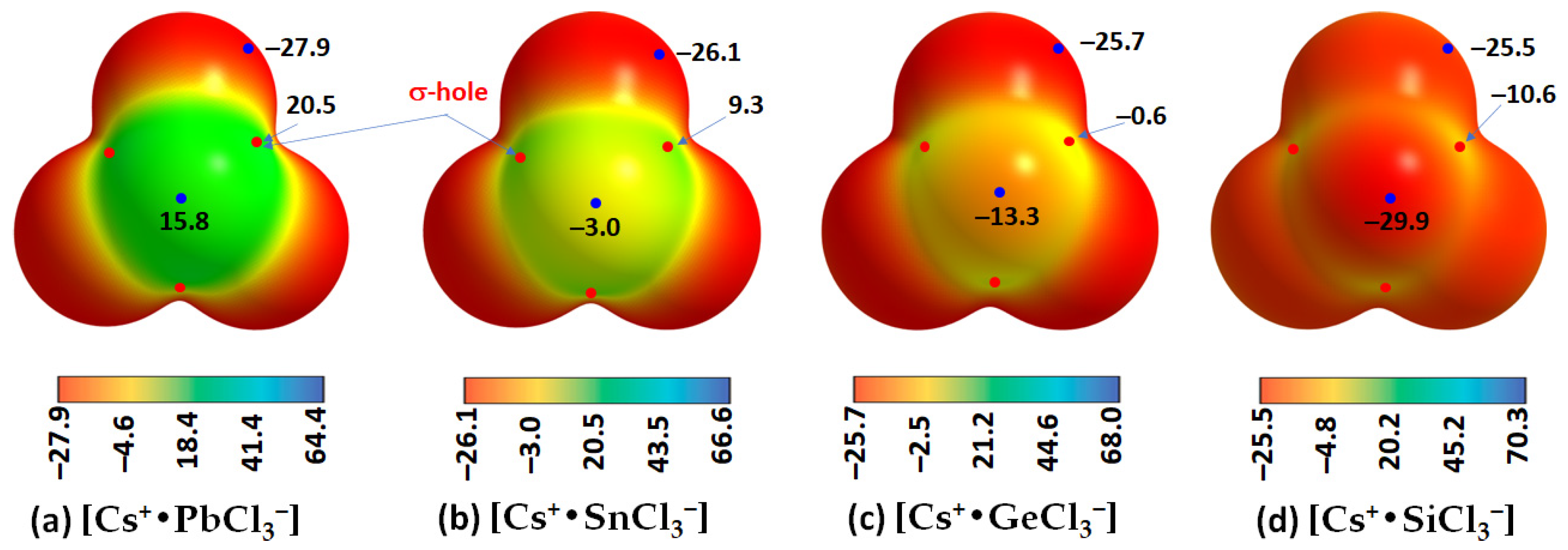
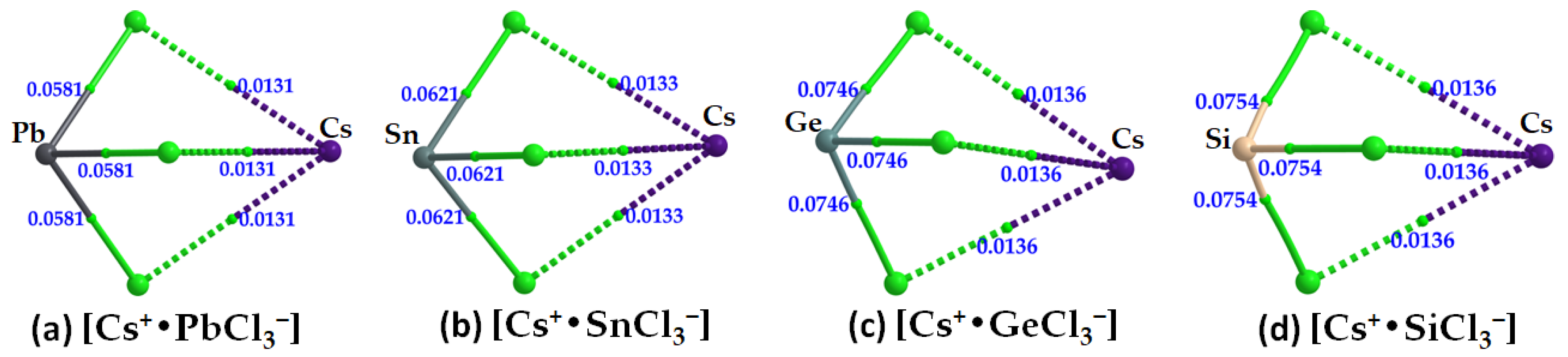
- Cesium Tetrel Chloride Perovskites
- (d)
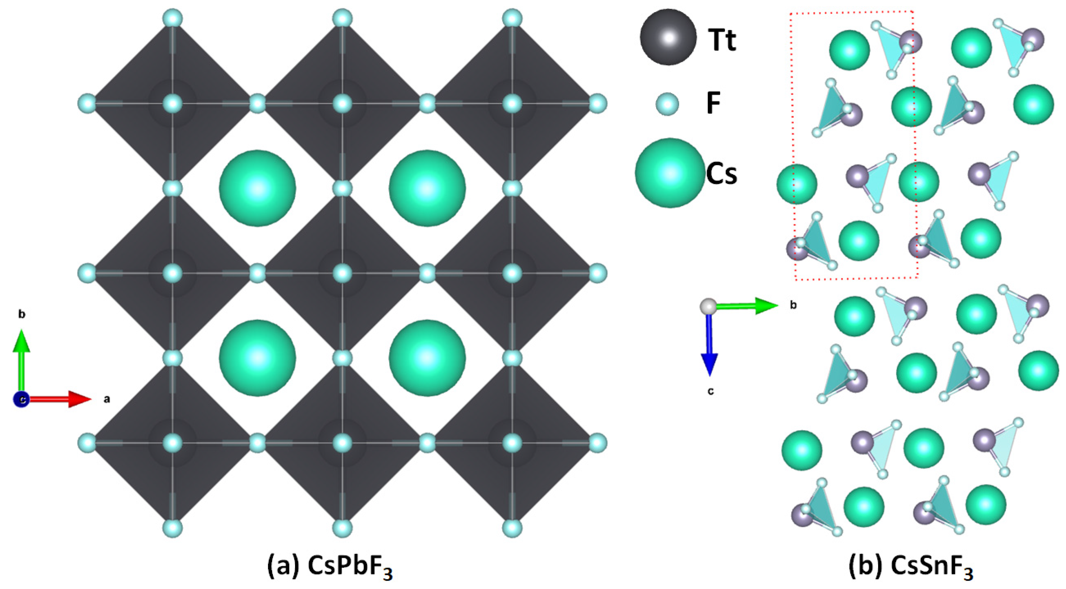
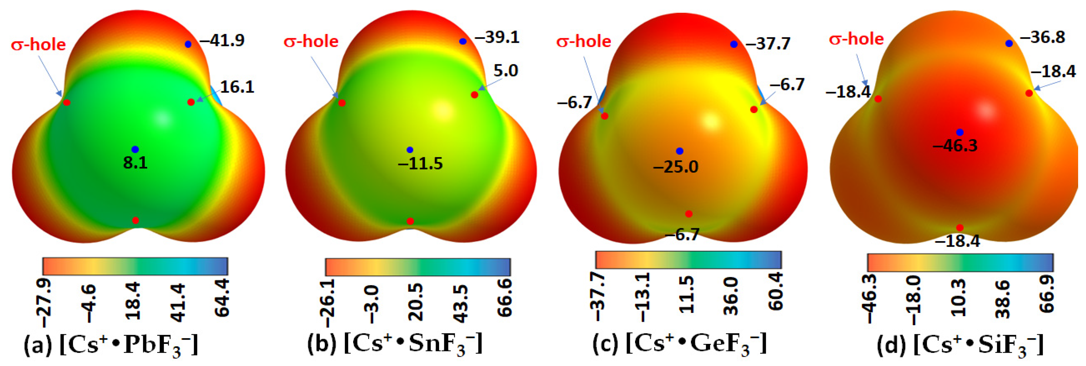
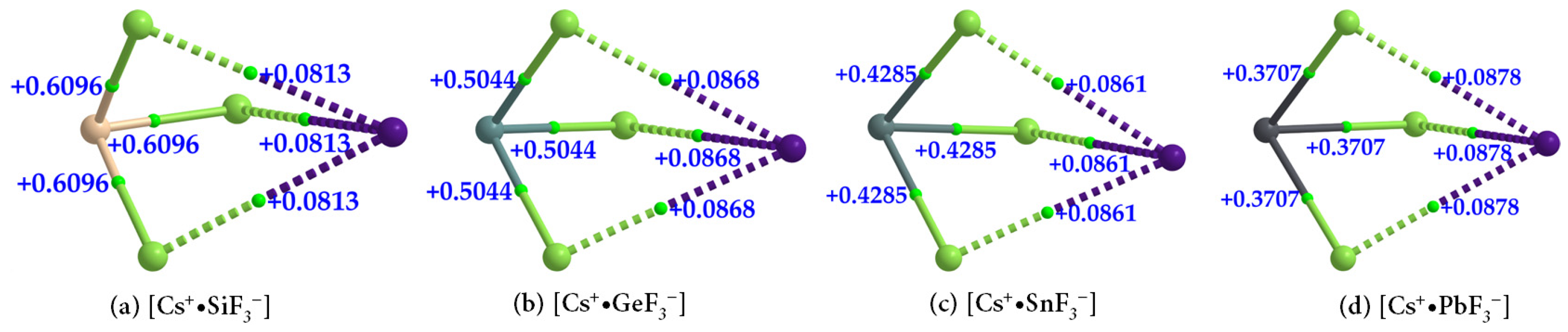
- Cesium Tetrel Fluoride Perovskites
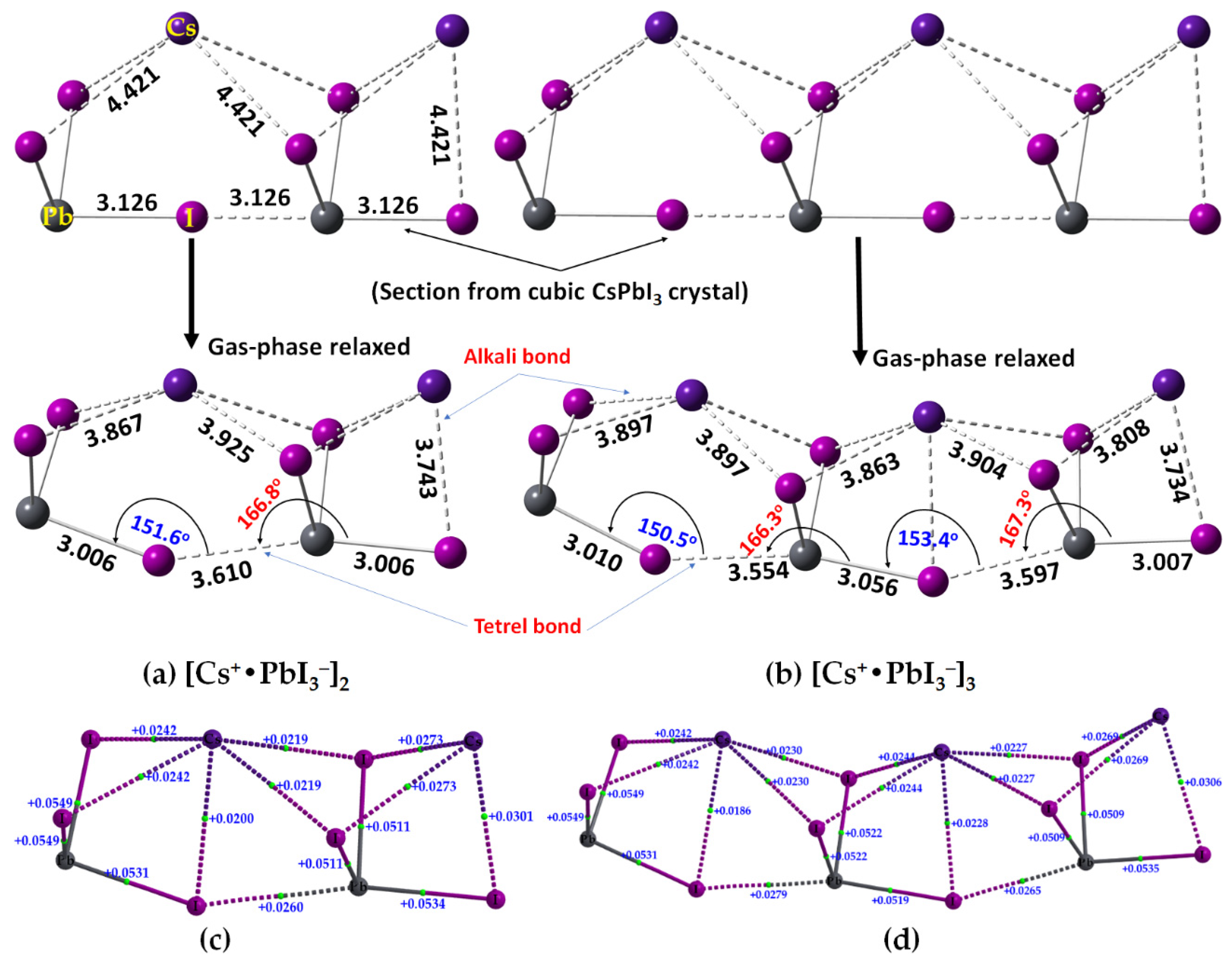
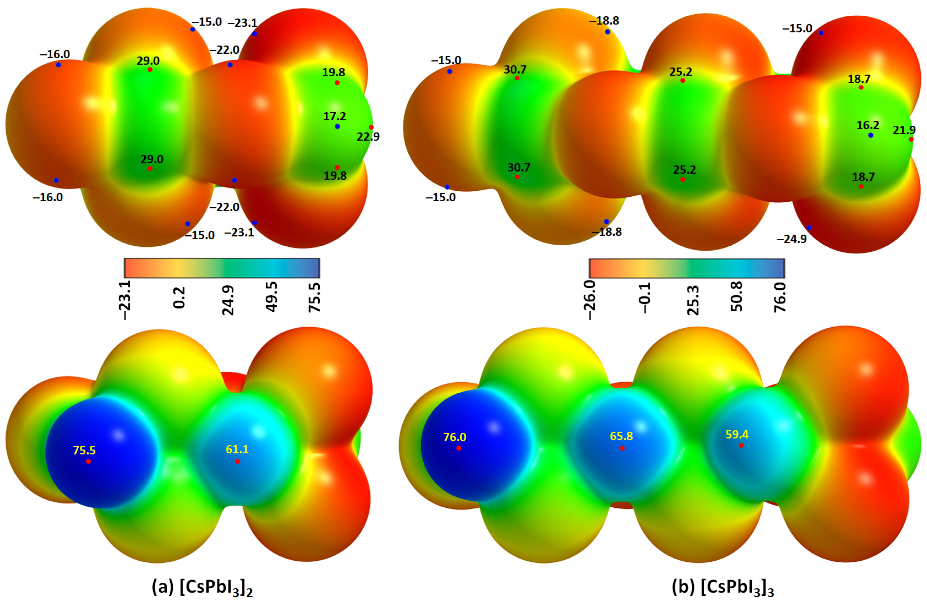
2.2. Oligomers of the [Cs+•PbI3−] Ion Pair
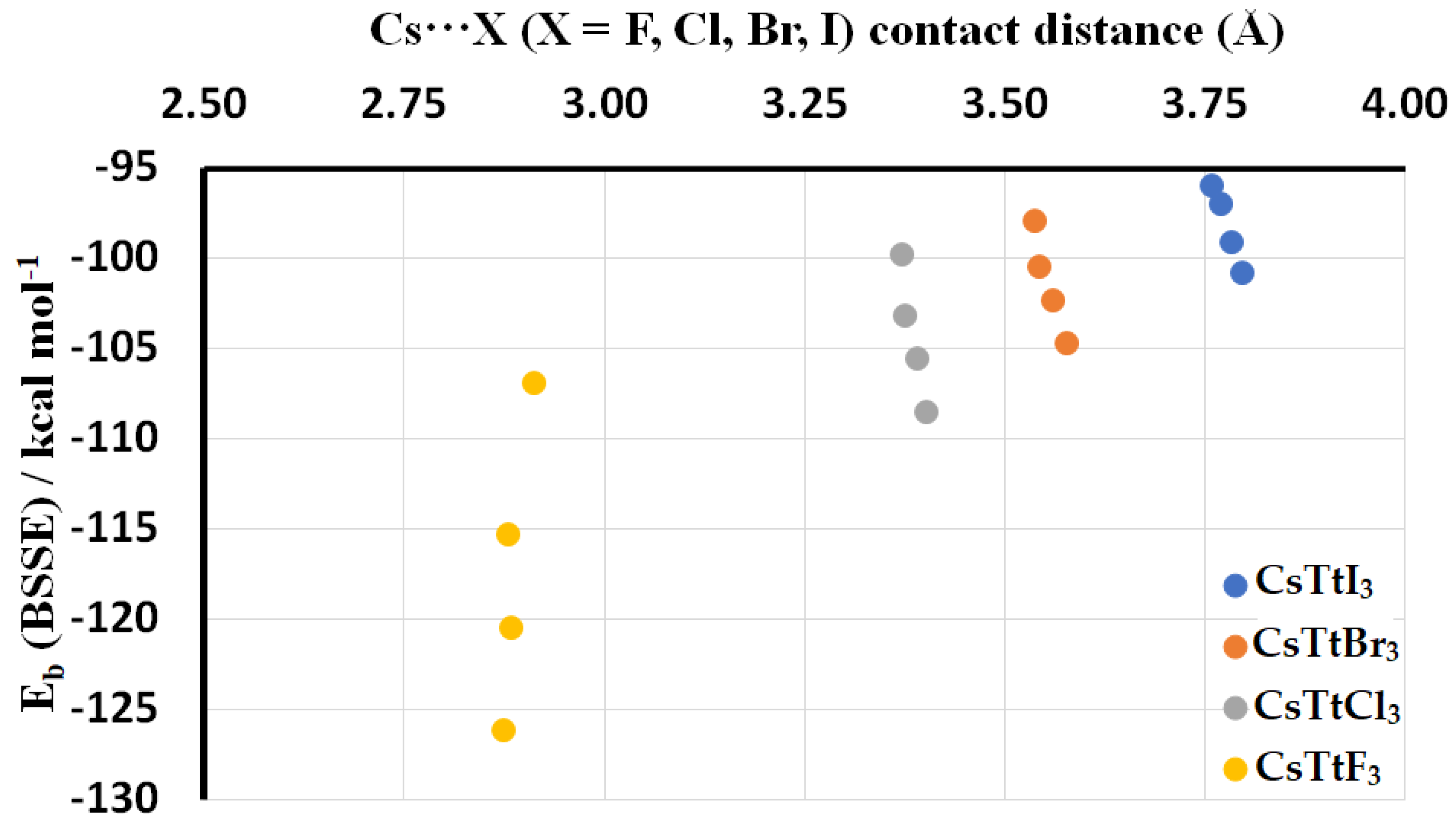
2.3. Stabilization Energy
3. Discussion
4. Materials and Methods
Computational Details
Author Contributions
Funding
Institutional Review Board Statement
Informed Consent Statement
Data Availability Statement
Acknowledgments
Conflicts of Interest
References
- Liang, J.; Qi, Y.B. Recent progress on all-inorganic metal halide perovskite solar cells. Mater. Today Nano 2021, 16, 100143. [Google Scholar] [CrossRef]
- Akkerman, Q.A.; Manna, L. What Defines a Halide Perovskite? ACS Energy Lett. 2020, 5, 604–610. [Google Scholar] [CrossRef] [PubMed]
- Varadwaj, P.R.; Marques, H.M. Physical and optoelectronic features of lead-free A2AgRhBr6 (A = Cs, Rb, K, Na, Li) with halide double perovskite composition. J. Mater. Chem. C 2020, 8, 12968–12983. [Google Scholar] [CrossRef]
- Bhandari, K.P.; Ellingson, R.J. An Overview of Hybrid Organic–Inorganic Metal Halide Perovskite Solar Cells. In A Comprehensive Guide to Solar Energy Systems; Letcher, T.M., Fthenakis, V.M., Eds.; Academic Press: London, UK, 2018; pp. 233–254. [Google Scholar]
- Varadwaj, A.; Varadwaj, P.R.; Marques, H.M.; Yamashita, K. Halogen in materials design: Revealing the nature of hydrogen bonding and other non-covalent interactions in the polymorphic transformations of methylammonium lead tribromide perovskite. Mater. Today Chem. 2018, 9, 1–16. [Google Scholar] [CrossRef]
- Varadwaj, P.R.; Varadwaj, A.; Marques, H.M.; Yamashita, K. Significance of hydrogen bonding and other noncovalent interactions in determining octahedral tilting in the CH3NH3PbI3 hybrid organic-inorganic halide perovskite solar cell semiconductor. Sci. Rep. 2019, 9, 50. [Google Scholar] [CrossRef]
- Varadwaj, A.; Varadwaj, P.R.; Marques, H.M.; Yamashita, K. The Pnictogen Bond, Together with Other Non-Covalent Interactions, in the Rational Design of One-, Two- and Three-Dimensional Organic-Inorganic Hybrid Metal Halide Perovskite Semiconducting Materials, and Beyond. Int. J. Mol. Sci. 2022, 23, 8816. [Google Scholar] [CrossRef] [PubMed]
- Kamat, P.V. Organometal halide perovskites for transformative photovoltaics. J. Am. Chem. Soc. 2014, 136, 3713–3714. [Google Scholar] [CrossRef]
- Wang, X.; Li, M.; Zhang, B.; Wang, H.; Zhao, Y.; Wang, B. Recent progress in organometal halide perovskite photodetectors. Org. Electron. 2018, 52, 172–183. [Google Scholar] [CrossRef]
- Yuan, J.; Liu, H.; Wang, S.; Li, X. How to apply metal halide perovskites to photocatalysis: Challenges and development. Nanoscale 2021, 13, 10281–10304. [Google Scholar] [CrossRef]
- Peighambardoust, N.S.; Sadeghi, E.; Aydemir, U. Lead Halide Perovskite Quantum Dots for Photovoltaics and Photocatalysis: A Review. ACS Appl. Nano Mater. 2022, 5, 14092–14132. [Google Scholar] [CrossRef]
- Ghosh, S.; Shankar, H.; Kar, P. Recent developments of lead-free halide double perovskites: A new superstar in the optoelectronic field. Mater. Adv. 2022, 3, 3742–3765. [Google Scholar] [CrossRef]
- Zhao, X.-G.; Yang, D.; Ren, J.-C.; Sun, Y.; Xiao, Z.; Zhang, L. Rational Design of Halide Double Perovskites for Optoelectronic Applications. Joule 2018, 2, 1662–1673. [Google Scholar] [CrossRef]
- Heidari Gourji, F.; Velauthapillai, D. A Review on Cs-Based Pb-Free Double Halide Perovskites: From Theoretical and Experimental Studies to Doping and Applications. Molecules 2021, 26, 2010. [Google Scholar] [CrossRef] [PubMed]
- Kakavelakis, G.; Gedda, M.; Panagiotopoulos, A.; Kymakis, E.; Anthopoulos, T.D.; Petridis, K. Metal Halide Perovskites for High-Energy Radiation Detection. Adv. Sci. 2020, 7, 2002098. [Google Scholar] [CrossRef] [PubMed]
- Mazumdar, S.; Zhao, Y.; Zhang, X. Stability of Perovskite Solar Cells: Degradation Mechanisms and Remedies. Front. Electron. 2021, 2, 712785. [Google Scholar] [CrossRef]
- Lin, H.; Zhou, C.; Tian, Y.; Siegrist, T.; Ma, B. Low-Dimensional Organometal Halide Perovskites. ACS Energy Lett. 2018, 3, 54–62. [Google Scholar] [CrossRef]
- Sun, S.; Lu, M.; Gao, X.; Shi, Z.; Bai, X.; Yu, W.W.; Zhang, Y. 0D Perovskites: Unique Properties, Synthesis, and Their Applications. Adv. Sci. 2021, 8, 2102689. [Google Scholar] [CrossRef] [PubMed]
- Aebli, M.; Benin, B.M.; McCall, K.M.; Morad, V.; Thöny, D.; Grützmacher, H.; Kovalenko, M.V. White CsPbBr3: Characterizing the One-Dimensional Cesium Lead Bromide Polymorph. Helv. Chim. Acta 2020, 103, e2000080. [Google Scholar] [CrossRef]
- Li, Q.; Lian, T. Ultrafast Charge Separation in Two-Dimensional CsPbBr3 Perovskite Nanoplatelets. J. Phys. Chem. Lett. 2019, 10, 566–573. [Google Scholar] [CrossRef]
- Zhang, L.; Liang, W. How the Structures and Properties of Two-Dimensional Layered Perovskites MAPbI3 and CsPbI3 Vary with the Number of Layers. J. Phys. Chem. Lett. 2017, 8, 1517–1523. [Google Scholar] [CrossRef]
- Kojima, K.; Teshima, Y.; Shirai, Y.; Miyasaka, T. Organometal halide perovskites as visible-light sensitizers for photovoltaic cells. J. Am. Chem. Soc. 2009, 131, 6050–6051. [Google Scholar] [CrossRef] [PubMed]
- Varadwaj, P.R. Methylammonium Lead Trihalide Perovskite Solar Cell Semiconductors Are Not Organometallic: A Perspective. Helv. Chim. Acta 2017, 100, e1700090. [Google Scholar] [CrossRef]
- De Angelis, F.; Kamat, P.V. Riding the New Wave of Perovskites. ACS Energy Lett. 2017, 2, 922–923. [Google Scholar] [CrossRef]
- Zhang, W.; Eperon, G.E.; Snaith, H.J. Metal halide perovskites for energy applications. Nat. Energy 2016, 1, 16048. [Google Scholar] [CrossRef]
- Yu, S.; Liu, P.; Xiao, S. A review of main characterization methods for identifying two-dimensional organic–inorganic halide perovskites. J. Mat. Sci. 2021, 56, 11656–11681. [Google Scholar] [CrossRef]
- Tang, D.-M.; Erohin, S.V.; Kvashnin, D.G.; Demin, V.A.; Cretu, O.; Jiang, S.; Zhang, L.; Hou, P.-X.; Chen, G.; Futaba, D.N.; et al. Semiconductor nanochannels in metallic carbon nanotubes by thermomechanical chirality alteration. Science 2021, 374, 1616–1620. [Google Scholar] [CrossRef] [PubMed]
- Varadwaj, A.; Varadwaj, P.R.; Yamashita, K. Revealing the Cooperative Chemistry of the Organic Cation in the Methylammonium Lead Triiodide Perovskite Semiconductor System. ChemistrySelect 2018, 3, 7269–7282. [Google Scholar] [CrossRef]
- Motta, C.; El-Mellouhi, F.; Kais, S.; Tabet, N.; Alharbi, F.; Sanvito, S. Revealing the role of organic cations in hybrid halide perovskite CH3NH3PbI3. Nat. Commun. 2015, 6, 7026. [Google Scholar] [CrossRef]
- Matheu, R.; Ke, F.; Breidenbach, A.; Wolf, N.R.; Lee, Y.; Liu, Z.; Leppert, L.; Lin, Y.; Karunadasa, H.I. Charge Reservoirs in an Expanded Halide Perovskite Analog: Enhancing High-Pressure Conductivity through Redox-Active Molecules. Angew. Chem. Int. Ed. 2022, 61, e202202911. [Google Scholar] [CrossRef]
- Liu, S.; Wang, J.; Hu, Z.; Duan, Z.; Zhang, H.; Zhang, W.; Guo, R.; Xie, F. Role of organic cation orientation in formamidine based perovskite materials. Sci. Rep. 2021, 11, 20433. [Google Scholar] [CrossRef]
- Sung, W.; Müller, C.; Hietzschold, S.; Lovrinčić, R.; Gallop, N.P.; Bakulin, A.A.; Nihonyanagi, S.; Tahara, T. Preferred orientations of organic cations at lead-halide perovskite interfaces revealed using vibrational sum-frequency spectroscopy. Mater. Horiz. 2020, 7, 1348–1357. [Google Scholar] [CrossRef]
- Cadillo, A.T.; Vargas, A.; Roa, A.; Garay-Tapia, A.M. The role of organic cations as additives in photovoltaic perovskites. In ChemRxiv; Cambridge Open Engage: Cambridge, UK, 2022; Available online: https://chemrxiv.org/engage/chemrxiv/article-details/62be0385d66f68ee9bb89111 (accessed on 2 April 2023).
- Teng, Q.; Shi, T.-T.; Tian, R.-Y.; Yang, X.-B.; Zhao, Y.-J. Role of organic cations on hybrid halide perovskite CH3NH3PbI3 surfaces. J. Solid State Chem. 2018, 258, 488–494. [Google Scholar] [CrossRef]
- Handayani, Y.S.; Indari, E.D.; Hidayat, R.; Othsubo, Y.; Kimura, S.-I. Understanding the role of organic cations on the electronic structure of lead iodide perovskite from their UV photoemission spectra and their electronic structures calculated by DFT method. Mater. Res. Express 2019, 6, 084009. [Google Scholar] [CrossRef]
- Varadwaj, P.R.; Varadwaj, A.; Marques, H.M.; Yamashita, K. Definition of the tetrel bond. CrystEngComm 2023, 25, 1411–1423. [Google Scholar] [CrossRef]
- Alkorta, I.; Elguero, J.; Frontera, A. Not Only Hydrogen Bonds: Other Noncovalent Interactions. Crystals 2020, 10, 180. [Google Scholar] [CrossRef]
- Clark, T.; Hennemann, M.; Murray, J.S.; Politzer, P. Halogen bonding: The σ-hole. J. Mol. Model. 2007, 13, 291–296. [Google Scholar] [CrossRef]
- Murray, J.S.; Lane, P.; Politzer, P. Expansion of the σ-hole concept. J. Mol. Model. 2009, 15, 723–729. [Google Scholar] [CrossRef]
- Politzer, P.; Murray, J.S.; Clark, T. Halogen bonding and other σ-hole interactions: A perspective. Phys. Chem. Chem. Phys. 2013, 15, 11178–11189. [Google Scholar] [CrossRef]
- Wang, H.; Wang, W.; Jin, W.J. σ-Hole Bond vs. π-Hole Bond: A Comparison Based on Halogen Bond. Chem. Rev. 2016, 116, 5072–5104. [Google Scholar] [CrossRef]
- Hellenbrandt, M. The Inorganic Crystal Structure Database (ICSD)—Present and Future. Crystallogr. Rev. 2004, 10, 17–22. [Google Scholar] [CrossRef]
- Inorganic Chemistry Structure Database (ICSD). Available online: https://icsd.products.fiz-karlsruhe.de/en (accessed on 25 January 2022).
- Jain, A.; Ong, S.P.; Hautier, G.; Chen, W.; Richards, W.D.; Dacek, S.; Cholia, S.; Gunter, D.; Skinner, D.; Ceder, G.; et al. Commentary: The Materials Project: A materials genome approach to accelerating materials innovation. APL Mater. 2013, 1, 011002. [Google Scholar] [CrossRef]
- Thiele, G.; Rotter, H.W.; Schmidt, K.D. Kristallstrukturen und Phasentransformationen von Caesiumtrihalogenogermanaten(II) CsGeX3 (X = Cl, Br, I). Zeit. Anorg. Allg. Chem. 1987, 545, 148–156. [Google Scholar] [CrossRef]
- Trots, D.M.; Myagkota, S.V. High-temperature structural evolution of caesium and rubidium triiodoplumbates. J. Phys. Chem. Solids 2008, 69, 2520–2526. [Google Scholar] [CrossRef]
- Bertolotti, F.; Protesescu, L.; Kovalenko, M.V.; Yakunin, S.; Cervellino, A.; Billinge, S.J.L.; Terban, M.W.; Pedersen, J.S.; Masciocchi, N.; Guagliardi, A. Coherent Nanotwins and Dynamic Disorder in Cesium Lead Halide Perovskite Nanocrystals. ACS Nano 2017, 11, 3819–3831. [Google Scholar] [CrossRef] [PubMed]
- Sutton, R.J.; Filip, M.R.; Haghighirad, A.A.; Sakai, N.; Wenger, B.; Giustino, F.; Snaith, H.J. Cubic or Orthorhombic? Revealing the Crystal Structure of Metastable Black-Phase CsPbI3 by Theory and Experiment. ACS Energy Lett. 2018, 3, 1787–1794. [Google Scholar] [CrossRef]
- Straus, D.B.; Guo, S.; Abeykoon, A.M.; Cava, R.J. Understanding the Instability of the Halide Perovskite CsPbI3 through Temperature-Dependent Structural Analysis. Adv. Mater. 2020, 32, 2001069. [Google Scholar] [CrossRef]
- Lee, J.-H.; Bristowe, N.C.; Lee, J.H.; Lee, S.-H.; Bristowe, P.D.; Cheetham, A.K.; Jang, H.M. Resolving the Physical Origin of Octahedral Tilting in Halide Perovskites. Chem. Mater. 2016, 28, 4259–4266. [Google Scholar] [CrossRef]
- Yin, J.; Xu, Z.; Hu, Q.; Teobaldi, G.; Liu, L.-M.; Prezhdo, O.V. Tuning Octahedral Tilting by Doping to Prevent Detrimental Phase Transition and Extend Carrier Lifetime in Organometallic Perovskites. J. Am. Chem. Soc. 2023, 145, 5393–5399. [Google Scholar] [CrossRef]
- Marronnier, A.; Roma, G.; Boyer-Richard, S.; Pedesseau, L.; Jancu, J.-M.; Bonnassieux, Y.; Katan, C.; Stoumpos, C.C.; Kanatzidis, M.G.; Even, J. Anharmonicity and Disorder in the Black Phases of Cesium Lead Iodide Used for Stable Inorganic Perovskite Solar Cells. ACS Nano 2018, 12, 3477–3486. [Google Scholar] [CrossRef]
- Chung, I.; Song, J.-H.; Im, J.; Androulakis, J.; Malliakas, C.D.; Li, H.; Freeman, A.J.; Kenney, J.T.; Kanatzidis, M.G. CsSnI3: Semiconductor or Metal? High Electrical Conductivity and Strong Near-Infrared Photoluminescence from a Single Material. High Hole Mobility and Phase-Transitions. J. Am. Chem. Soc. 2012, 134, 8579–8587. [Google Scholar] [CrossRef]
- Wang, L.; Chen, P.; Kuttipillai, P.S.; King, I.; Staples, R.; Sun, K.; Lunt, R.R. Epitaxial Stabilization of Tetragonal Cesium Tin Iodide. ACS Appl. Mater. Interfaces 2019, 11, 32076–32083. [Google Scholar] [CrossRef] [PubMed]
- Yamanaka, H.; Hihara, G.; Miyamae, H. Crystal Structure of PbI2(ethylenediamine)2-catena m-Ethylenediamine-ethylenediaminediiodolead(II) at −150 °C. Anal. Sci. X-ray Struct. Anal. Online 2008, 24, x121–x122. [Google Scholar] [CrossRef]
- Fabini, D.H.; Laurita, G.; Bechtel, J.S.; Stoumpos, C.C.; Evans, H.A.; Kontos, A.G.; Raptis, Y.S.; Falaras, P.; Van der Ven, A.; Kanatzidis, M.G.; et al. Dynamic Stereochemical Activity of the Sn2+ Lone Pair in Perovskite CsSnBr3. J. Am. Chem. Soc. 2016, 138, 11820–11832. [Google Scholar] [CrossRef] [PubMed]
- Walsh, A.; Watson, G.W. The origin of the stereochemically active Pb(II) lone pair: DFT calculations on PbO and PbS. J. Solid State Chem. 2005, 178, 1422–1428. [Google Scholar] [CrossRef]
- Straus, D.B.; Mitchell Warden, H.E.; Cava, R.J. s–p Mixing in Stereochemically Active Lone Pairs Drives the Formation of 1D Chains of Lead Bromide Square Pyramids. Inorg. Chem. 2021, 60, 12676–12680. [Google Scholar] [CrossRef]
- Schmitz-Dumont, O.; Bergerhoff, G.; Hartert, E. Über den Einfluß des Kationenradius auf die Bildungsenergie von Anlagerungsverbindungen. VII. Die Systeme Alkalifluorid/Bleifluorid. Zeit. Anorg. Allg. Chem. 1956, 283, 314–329. [Google Scholar] [CrossRef]
- Smith, E.H.; Benedek, N.A.; Fennie, C.J. Interplay of Octahedral Rotations and Lone Pair Ferroelectricity in CsPbF3. Inorg. Chem. 2015, 54, 8536–8543. [Google Scholar] [CrossRef]
- Thao Tran, T.; Shiv Halasyamani, P. Synthesis and characterization of ASnF3 (A = Na+, K+, Rb+, Cs+). J. Solid State Chem. 2014, 210, 213–218. [Google Scholar] [CrossRef]
- Zhang, B.-B.; Liu, X.; Xiao, B.; Hafsia, A.B.; Gao, K.; Xu, Y.; Zhou, J.; Chen, Y. High-Performance X-ray Detection Based on One-Dimensional Inorganic Halide Perovskite CsPbI3. J. Phys. Chem. Lett. 2020, 11, 432–437. [Google Scholar] [CrossRef]
- Lai, M.; Kong, Q.; Bischak, C.G.; Yu, Y.; Dou, L.; Eaton, S.W.; Ginsberg, N.S.; Yang, P. Structural, optical, and electrical properties of phase-controlled cesium lead iodide nanowires. Nano Res. 2017, 10, 1107–1114. [Google Scholar] [CrossRef]
- Wang, B.; Novendra, N.; Navrotsky, A. Energetics, Structures, and Phase Transitions of Cubic and Orthorhombic Cesium Lead Iodide (CsPbI3) Polymorphs. J. Am. Chem. Soc. 2019, 141, 14501–14504. [Google Scholar] [CrossRef] [PubMed]
- Klarbring, J. Low-energy paths for octahedral tilting in inorganic halide perovskites. Phys. Rev. B 2019, 99, 104105. [Google Scholar] [CrossRef]
- Liu, D.; Shao, Z.; Li, C.; Pang, S.; Yan, Y.; Cui, G. Structural Properties and Stability of Inorganic CsPbI3 Perovskites. Small Struct. 2021, 2, 2000089. [Google Scholar] [CrossRef]
- Varadwaj, P.R. Tetrel Bonding in Anion Recognition: A First Principles Investigation. Molecules 2022, 27, 8449. [Google Scholar] [CrossRef] [PubMed]
- Wolters, L.P.; Bickelhaupt, F.M. Halogen bonding versus hydrogen bonding: A molecular orbital perspective. ChemistryOpen 2012, 1, 96–105. [Google Scholar] [CrossRef]
- Santos, L.D.A.; Hamlin, T.A.; Ramalho, T.C.; Bickelhaupt, F.M. The pnictogen bond: A quantitative molecular orbital picture. Phys. Chem. Chem. Phys. 2021, 23, 13842–13852. [Google Scholar] [CrossRef] [PubMed]
- Varadwaj, A.; Varadwaj, P.R.; Yamashita, K. Revealing the Chemistry between Bandgap and Binding Energy for Pb/Sn-based Trihalide Perovskite Solar Cell Semiconductors. ChemSusChem 2018, 11, 449–463. [Google Scholar] [CrossRef] [PubMed]
- Espinosa, E.; Molins, E.; Lecomte, C. Hydrogen bond strengths revealed by topological analyses of experimentally ob-served electron densities. Chem. Phys. Lett. 1998, 285, 170–173. [Google Scholar] [CrossRef]
- Chai, J.-D.; Head-Gordon, M. Long-range corrected hybrid density functionals with damped atom–atom dispersion corrections. Phys. Chem. Chem. Phys. 2008, 10, 6615–6620. [Google Scholar] [CrossRef]
- Frisch, M.J.; Trucks, G.W.; Schlegel, H.B.; Scuseria, G.E.; Robb, M.A.; Cheeseman, J.R.; Scalmani, G.; Barone, V.; Petersson, G.A.; Nakatsuji, H.; et al. Gaussian 16, Revision C.01; Gaussian, Inc.: Wallingford, CT, USA, 2016. [Google Scholar]
- Pritchard, B.P.; Altarawy, D.; Didier, B.; Gibson, T.D.; Windus, T.L. New Basis Set Exchange: An Open, Up-to-Date Resource for the Molecular Sciences Community. J. Chem. Inf. Model. 2019, 59, 4814–4820. [Google Scholar] [CrossRef]
- Minenkov, Y.; Singstad, A.; Occhipinti, G.; Jensen, V.R. The accuracy of DFT-optimized geometries of functional transition metal compounds: A validation study of catalysts for olefin metathesis and other reactions in the homogeneous phase. Dalton Trans. 2012, 41, 5526–5541. [Google Scholar] [CrossRef] [PubMed]
- Wang, T.; Daiber, B.; Frost, J.M.; Mann, S.A.; Garnett, E.C.; Walsh, A.; Ehrler, B. Indirect to direct bandgap transition in methylammonium lead halide perovskite. Energy Environ. Sci. 2017, 10, 509–515. [Google Scholar] [CrossRef]
- Walsh, A. Atomistic models of metal halide perovskites. Matter 2021, 4, 3867–3873. [Google Scholar] [CrossRef]
- Kepenekian, M.; Even, J. Rashba and Dresselhaus Couplings in Halide Perovskites: Accomplishments and Opportunities for Spintronics and Spin–Orbitronics. J. Chem. Phys. Lett. 2017, 8, 3362–3370. [Google Scholar] [CrossRef] [PubMed]
- Scheiner, S. Tetrel Bonding as a Vehicle for Strong and Selective Anion Binding. Molecules 2018, 23, 1147. [Google Scholar] [CrossRef] [PubMed]
- Scheiner, S. Origins and properties of the tetrel bond. Phys. Chem. Chem. Phys. 2021, 23, 5702–5717. [Google Scholar] [CrossRef]
- Grabowski, S.J. Tetrel Bonds with π-Electrons Acting as Lewis Bases—Theoretical Results and Experimental Evidences. Molecules 2018, 23, 1183. [Google Scholar]
- Scheiner, S. Systematic Elucidation of Factors That Influence the Strength of Tetrel Bonds. J. Phys. Chem. A 2017, 121, 5561–5568. [Google Scholar] [CrossRef]
- Boys, S.F.; Bernardi, F. The calculation of small molecular interactions by the differences of separate total energies. Some procedures with reduced errors. Mol. Phys. 1970, 19, 553–566. [Google Scholar] [CrossRef]
- Bader, R.F. Atoms in Molecules: A Quantum Theory; Oxford University Press: Oxford, UK, 1990. [Google Scholar]
- Chan, W.-T.; Hamilton, I.P. Valence shell structures in the distributions of the Laplacian of the electron density and the one-electron potential for diatomic molecules. J. Chem. Phys. 1998, 108, 2473–2485. [Google Scholar] [CrossRef]
- Macchi, P.; Prosperio, D.M.; Sironi, A. Experimental Electron Density in a Transition Metal Dimer: Metal–Metal and Metal–Ligand Bonds. J. Am. Chem. Soc. 1998, 120, 13429–13435. [Google Scholar] [CrossRef]
- Tsirelson, V.G. Topological analysis of the experimental electron density. Can. J. Chem. 1996, 74, 1171–1179. [Google Scholar] [CrossRef]
- Koch, U.; Popelier, P.L.A. Characterization of C-H---O Hydrogen Bonds on the Basis of the Charge Density. J. Phys. Chem. 1995, 99, 9747–9754. [Google Scholar] [CrossRef]
- Popelier, P.L.A. On the full topology of the Laplacian of the electron density. Coord. Chem. Rev. 2000, 197, 169–189. [Google Scholar] [CrossRef]
- Gibbs, G.V.; Downs, R.T.; Cox, D.F.; Rosso, K.M.; Ross, N.L.; Kirfel, A.; Lippmann, T.; Morgenroth, W.; Crawford, T.D. Experimental Bond Critical Point and Local Energy Density Properties Determined for Mn-O, Fe-O, and Co-O Bonded Interactions for Tephroite, Mn2SiO4, Fayalite, Fe2SiO4 and Co2SiO4 Olivine and Selected Organic Metal Complexes: Comparison with Properties Calculated for Non-Transition and Transition Metal M-O Bonded Interactions for Silicates and Oxides. J. Phys Chem. A 2008, 112, 8811–8823. [Google Scholar] [CrossRef]
- Cremer, D.; Kraka, E. A Description of the Chemical Bond in Terms of Local Properties of Electron Density and Energy. Croat. Chem. Acta 1984, 57, 1259–1281. [Google Scholar]
- Cremer, D.; Kraka, E. Chemical Bonds without Bonding Electron Density—Does the Difference Electron-Density Analysis Suffice for a Description of the Chemical Bond? Angew. Chem. Int. Ed. 1984, 23, 627–628. [Google Scholar] [CrossRef]
- Bianchi, R.; Gervasio, G.; Marabello, D. The experimental charge density in transition metal compounds. Comptes Rendus Chim. 2005, 8, 1392–1399. [Google Scholar] [CrossRef]
- Suresh, C.H.; Remya, G.S.; Anjalikrishna, P.K. Molecular electrostatic potential analysis: A powerful tool to interpret and predict chemical reactivity. WIREs Comput. Mol. Sci. 2022, 12, e1601. [Google Scholar] [CrossRef]
- Murray, J.S.; Politzer, P. The Molecular Electrostatic Potential: A Tool for Understanding and Predicting Molecular Interactions. In Molecular Orbital Calculations for Biological Systems; Sapse, A.-M., Ed.; Oxford University Press: Oxford, UK, 1998; pp. 49–84. [Google Scholar]
- Politzer, P.; Laurence, P.R.; Jayasuriya, K. Molecular electrostatic potentials: An effective tool for the elucidation of biochemical phenomena. Environ. Health Perspect. 1985, 61, 191–202. [Google Scholar] [CrossRef]
- Varadwaj, A.; Marques, H.M.; Varadwaj, P.R. Is the Fluorine in Molecules Dispersive? Is Molecular Electrostatic Potential a Valid Property to Explore Fluorine-Centered Non-Covalent Interactions? Molecules 2019, 24, 379. [Google Scholar] [CrossRef] [PubMed]
- Varadwaj, A.; Marques, H.M.; Varadwaj, P.R. Nature of halogen-centered intermolecular interactions in crystal growth and design: Fluorine-centered interactions in dimers in crystalline hexafluoropropylene as a prototype. J. Comput. Chem. 2019, 40, 1836–1860. [Google Scholar] [CrossRef] [PubMed]
- Varadwaj, P.R.; Varadwaj, A.; Marques, H.M. Halogen Bonding: A Halogen-Centered Noncovalent Interaction Yet to Be Understood. Inorganics 2019, 7, 40. [Google Scholar] [CrossRef]
- Varadwaj, P.R.; Varadwaj, A.; Marques, H.M.; Yamashita, K. Can Combined Electrostatic and Polarization Effects Alone Explain the F···F Negative-Negative Bonding in Simple Fluoro-Substituted Benzene Derivatives? A First-Principles Perspective. Computation 2018, 6, 51. [Google Scholar] [CrossRef]
- Varadwaj, P.R.; Varadwaj, A.; Marques, H.M.; Yamashita, K. The Nitrogen Bond, or the Nitrogen-Centered Pnictogen Bond: The Covalently Bound Nitrogen Atom in Molecular Entities and Crystals as a Pnictogen Bond Donor. Compounds 2022, 2, 80–110. [Google Scholar] [CrossRef]
- Varadwaj, P.R.; Varadwaj, A.; Marques, H.M.; Yamashita, K. The Phosphorus Bond, or the Phosphorus-Centered Pnictogen Bond: The Covalently Bound Phosphorus Atom in Molecular Entities and Crystals as a Pnictogen Bond Donor. Molecules 2022, 27, 1487. [Google Scholar] [CrossRef]
- Varadwaj, A.; Varadwaj, P.R.; Marques, H.M.; Yamashita, K. The Pnictogen Bond: The Covalently Bound Arsenic Atom in Molecular Entities in Crystals as a Pnictogen Bond Donor. Molecules 2022, 27, 3421. [Google Scholar] [CrossRef]
- Varadwaj, A.; Varadwaj, P.R.; Marques, H.M.; Yamashita, K. The Stibium Bond or the Antimony-Centered Pnictogen Bond: The Covalently Bound Antimony Atom in Molecular Entities in Crystal Lattices as a Pnictogen Bond Donor. Int. J. Mol. Sci. 2022, 23, 4674. [Google Scholar] [CrossRef]
- Politzer, P.; Murray, J.S. σ-Hole Interactions: Perspectives and Misconceptions. Crystals 2017, 7, 212. [Google Scholar] [CrossRef]
- Politzer, P.; Murray, J.S.; Clark, T.; Resnati, G. The σ-hole revisited. Phys. Chem. Chem. Phys. 2017, 19, 32166–32178. [Google Scholar] [CrossRef]
- Varadwaj, P.R.; Varadwaj, A.; Marques, H.M. Does Chlorine in CH3Cl Behave as a Genuine Halogen Bond Donor? Crystals 2020, 10, 146. [Google Scholar] [CrossRef]
- Keith, T.A. AIMAll (V. 19.10.12). TK Gristmill Software. 2019. Available online: https://aim.tkgristmill.com (accessed on 2 April 2023).
- Lu, T.; Chen, F. A multifunctional wavefunction analyzer. J. Comput. Chem. 2012, 33, 580–592. [Google Scholar] [CrossRef]


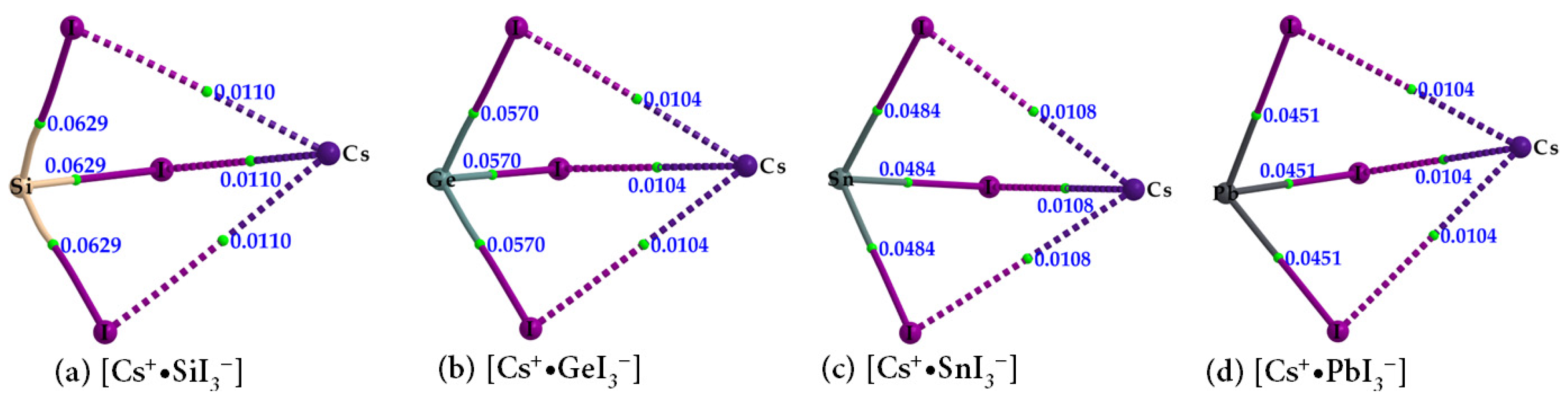
| Species | Bond Type | ρb/a.u. | ∇2ρb/a.u. | Hb/a.u. |
|---|---|---|---|---|
| Cs+•SiI3− | Cs···I | 0.0110 | 0.0292 | 0.0008 |
| Si–I | 0.0629 | −0.0515 | −0.0293 | |
| Cs+•GeI3− | Cs···I | 0.0104 | 0.0285 | 0.0009 |
| Ge–I | 0.0570 | 0.0064 | −0.0188 | |
| Cs+•SnI3− | Cs···I | 0.0108 | 0.0284 | 0.0008 |
| Sn–I | 0.0484 | 0.0386 | −0.0119 | |
| Cs+•PbI3− | Cs···I | 0.0104 | 0.0274 | 0.0008 |
| Pb–I | 0.0451 | 0.0536 | −0.0088 |
| Species | Bond Type | ρb/a.u. | ∇2ρb/a.u. | Hb/a.u. |
|---|---|---|---|---|
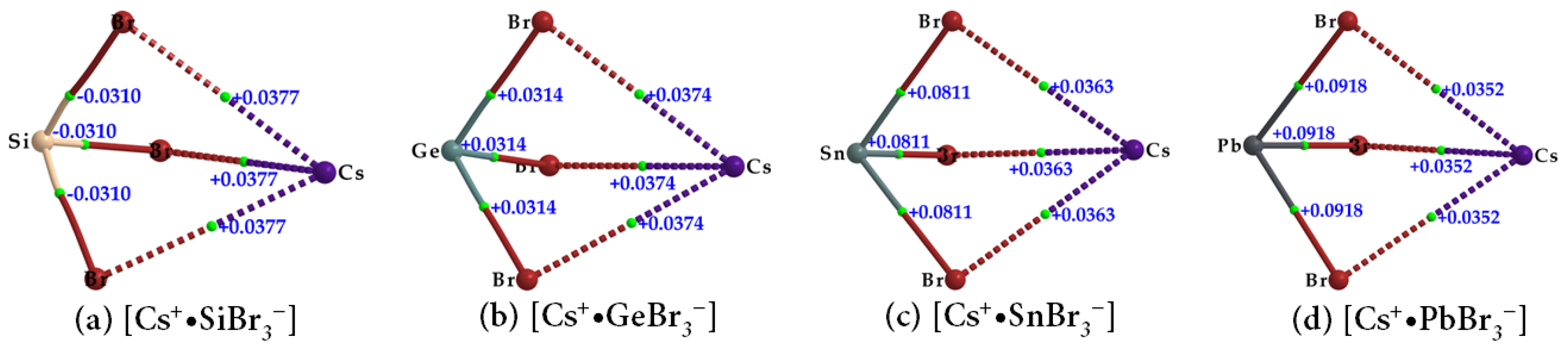
| Cs+•SiBr3− | Cs···Br | 0.0122 | 0.0377 | 0.0011 |
| Si–Br | 0.0689 | −0.0310 | −0.0371 | |
| Cs+•GeBr3− | Cs···Br | 0.0122 | 0.0374 | 0.0011 |
| Ge–Br | 0.0662 | 0.0314 | −0.0245 | |
| Cs+•SnBr3− | Cs···Br | 0.0119 | 0.0363 | 0.0011 |
| Sn–Br | 0.0547 | 0.0811 | −0.0121 | |
| Cs+•PbBr3− | Cs···Br | 0.0116 | 0.0352 | 0.0011 |
| Pb–Br | 0.0514 | 0.0918 | −0.0092 |
| Species | Bond Type | ρb/a.u. | ∇2ρb/a.u. | Hb/a.u. |
|---|---|---|---|---|
| Cs+•SiCl3− | Cs···Cl | 0.0136 | 0.0472 | 0.0017 |
| Si–Cl | 0.0754 | 0.0502 | −0.0400 | |
| Cs+•GeCl3− | Cs···Cl | 0.0136 | 0.0468 | 0.0016 |
| Ge–Cl | 0.0746 | 0.0778 | −0.0287 | |
| Cs+•SnCl3− | Cs···Cl | 0.0133 | 0.0455 | 0.0016 |
| Sn–Cl | 0.0621 | 0.1268 | −0.0147 | |
| Cs+•PbCl3− | Cs···Cl | 0.0131 | 0.0445 | 0.0016 |
| Pb–Cl | 0.0581 | 0.1311 | −0.0111 |
| Species | Bond Type | ρb/a.u. | ∇2ρb/a.u. | Hb/a.u. |
|---|---|---|---|---|
| Cs+•SiF3− | Cs···F | 0.0181 | 0.0813 | 0.0028 |
| Si–F | 0.1060 | 0.6096 | −0.0327 | |
| Cs+•GeF3− | Cs···F | 0.0196 | 0.0868 | 0.0028 |
| Ge–F | 0.1070 | 0.5044 | −0.0316 | |
| Cs+•SnF3− | Cs···F | 0.0197 | 0.0861 | 0.0026 |
| Sn–F | 0.0911 | 0.4285 | −0.0209 | |
| Cs+•PbF3− | Cs···F | 0.0202 | 0.0878 | 0.0026 |
| Pb–F | 0.0828 | 0.3707 | −0.0152 |
| Property | [Cs+•PbI3−]2 | [Cs+•PbI3−]3 |
|---|---|---|
| Pb–I coordinate bond | ||
| ρb/a.u. | 0.0411–0.0472 | 0.0379–0.0474 |
| ∇2ρb/a.u. | 0.0511–0.0116 | 0.0509–0.0549 |
| Hb/a.u. | −(0.0071–0.0072) | −(0.0058–0.0097) |
| Cs···I alkali bond | ||
| ρb/a.u. | 0.0075–0.0116 | 0.0069–0.0103 |
| ∇2ρb/a.u. | 0.0020–0.0301 | 0.0186–0.0269 |
| Hb/a.u. | 0.00078 | 0.00078 |
| Pb···I tetrel bond | ||
| ρb/a.u. | 0.0139 | 0.0152 (0.0143) a |
| ∇2ρb/a.u. | 0.0260 | 0.0279 (0.0265) a |
| Hb/a.u. | 0.00013 | −0.000083 (0.000018) a |
| Ion Pair | Eb (kcal mol−1) | Eb(BSSE) (kcal mol−1) | r(Cs···X) (Å) | r(Tt–X) (Å) |
|---|---|---|---|---|
| [Cs+•SiI3−] | −96.07 | −96.05 | 3.759 | 2.635 |
| [Cs+•GeI3−] | −97.10 | −97.02 | 3.770 | 2.723 |
| [Cs+•SnI3−] | −99.13 | −99.11 | 3.785 | 2.889 |
| [Cs+•PbI3−] | −100.89 | −100.87 | 3.798 | 2.969 |
| [Cs+•SiBr3−] | −98.13 | −98.00 | 3.539 | 2.403 |
| [Cs+•GeBr3−] | −100.66 | −100.50 | 3.544 | 2.500 |
| [Cs+•SnBr3−] | −102.51 | −102.38 | 3.561 | 2.668 |
| [Cs+•PbBr3−] | −104.84 | −104.72 | 3.578 | 2.754 |
| [Cs+•SiCl3−] | −99.92 | −99.81 | 3.373 | 2.226 |
| [Cs+•GeCl3−] | −103.37 | −103.24 | 3.377 | 2.335 |
| [Cs+•SnCl3−] | −105.74 | −105.63 | 3.392 | 2.506 |
| [Cs+•PbCl3−] | −108.68 | −108.58 | 3.403 | 2.600 |
| [Cs+•SiF3−] | −106.99 | −106.91 | 2.914 | 1.706 |
| [Cs+•GeF3−] | −115.46 | −115.37 | 2.881 | 1.852 |
| [Cs+•SnF3−] | −120.61 | −120.54 | 2.885 | 2.033 |
| [Cs+•PbF3−] | −126.32 | −126.24 | 2.876 | 2.144 |
Disclaimer/Publisher’s Note: The statements, opinions and data contained in all publications are solely those of the individual author(s) and contributor(s) and not of MDPI and/or the editor(s). MDPI and/or the editor(s) disclaim responsibility for any injury to people or property resulting from any ideas, methods, instructions or products referred to in the content. |
© 2023 by the authors. Licensee MDPI, Basel, Switzerland. This article is an open access article distributed under the terms and conditions of the Creative Commons Attribution (CC BY) license (https://creativecommons.org/licenses/by/4.0/).
Share and Cite
Varadwaj, P.R.; Varadwaj, A.; Marques, H.M.; Yamashita, K. The Tetrel Bond and Tetrel Halide Perovskite Semiconductors. Int. J. Mol. Sci. 2023, 24, 6659. https://doi.org/10.3390/ijms24076659
Varadwaj PR, Varadwaj A, Marques HM, Yamashita K. The Tetrel Bond and Tetrel Halide Perovskite Semiconductors. International Journal of Molecular Sciences. 2023; 24(7):6659. https://doi.org/10.3390/ijms24076659
Chicago/Turabian StyleVaradwaj, Pradeep R., Arpita Varadwaj, Helder M. Marques, and Koichi Yamashita. 2023. "The Tetrel Bond and Tetrel Halide Perovskite Semiconductors" International Journal of Molecular Sciences 24, no. 7: 6659. https://doi.org/10.3390/ijms24076659
APA StyleVaradwaj, P. R., Varadwaj, A., Marques, H. M., & Yamashita, K. (2023). The Tetrel Bond and Tetrel Halide Perovskite Semiconductors. International Journal of Molecular Sciences, 24(7), 6659. https://doi.org/10.3390/ijms24076659