
The Latest Advances in Ink-Based Nanogenerators: From Materials to Applications


Abstract
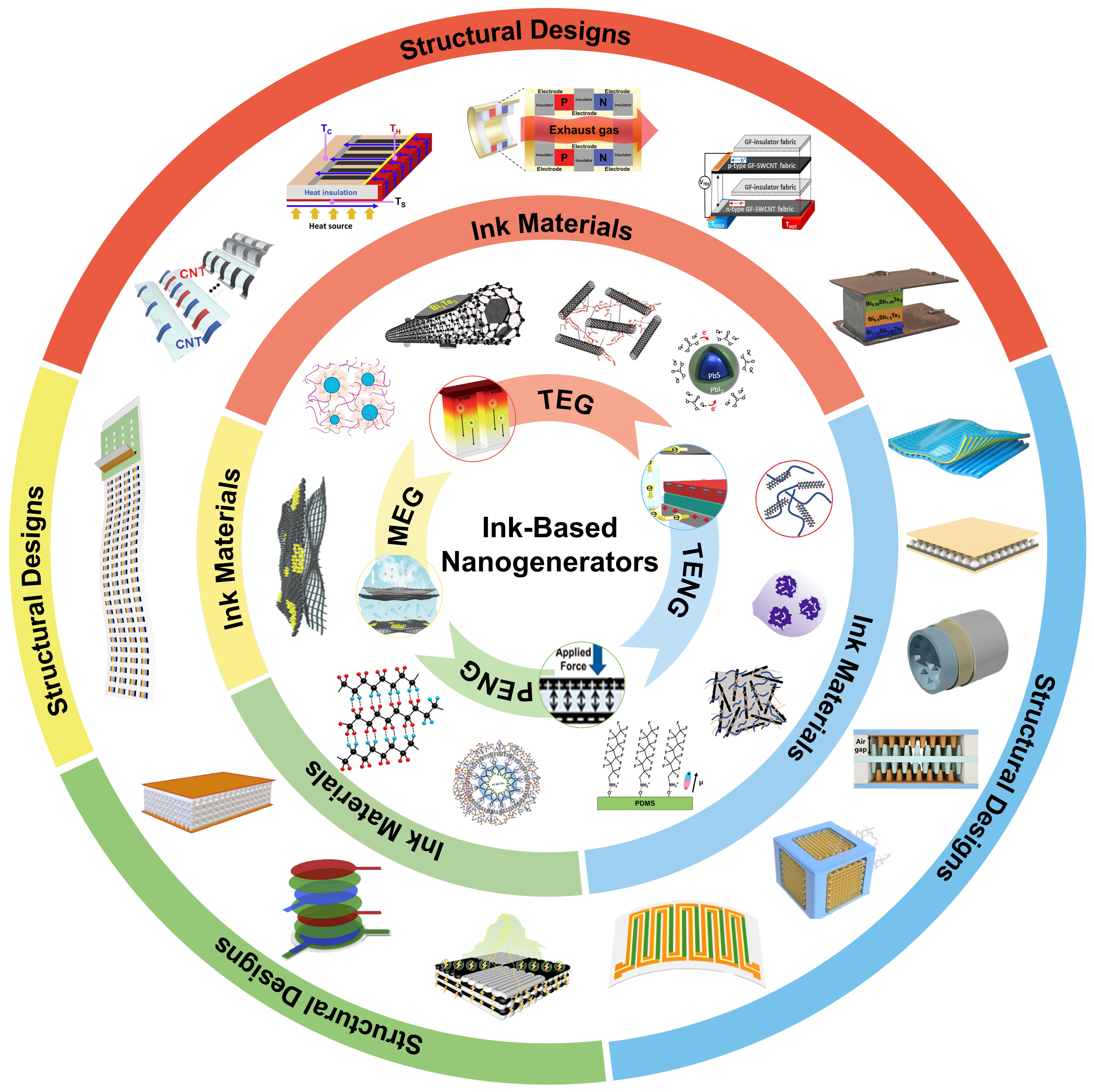
:1. Introduction
2. Ink-Based TEGs
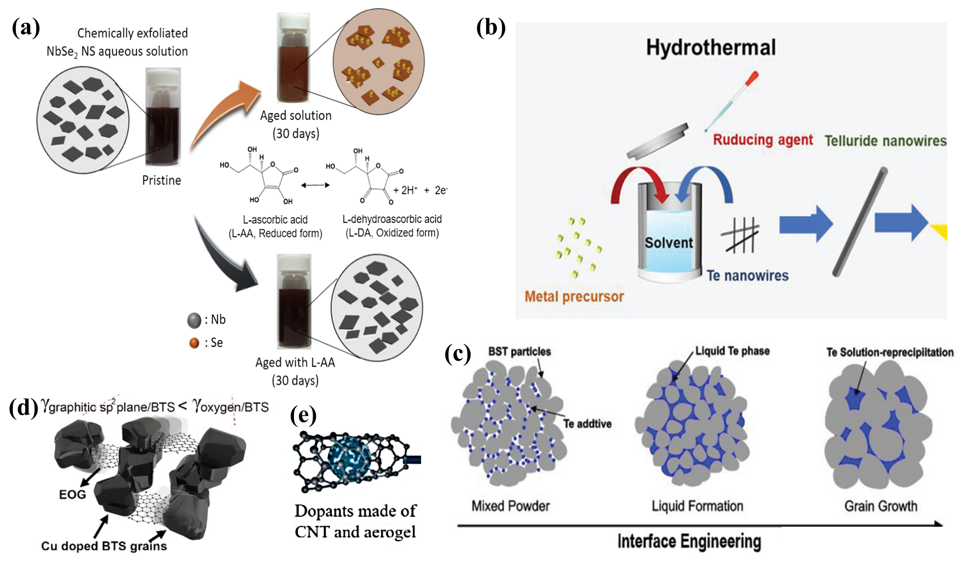
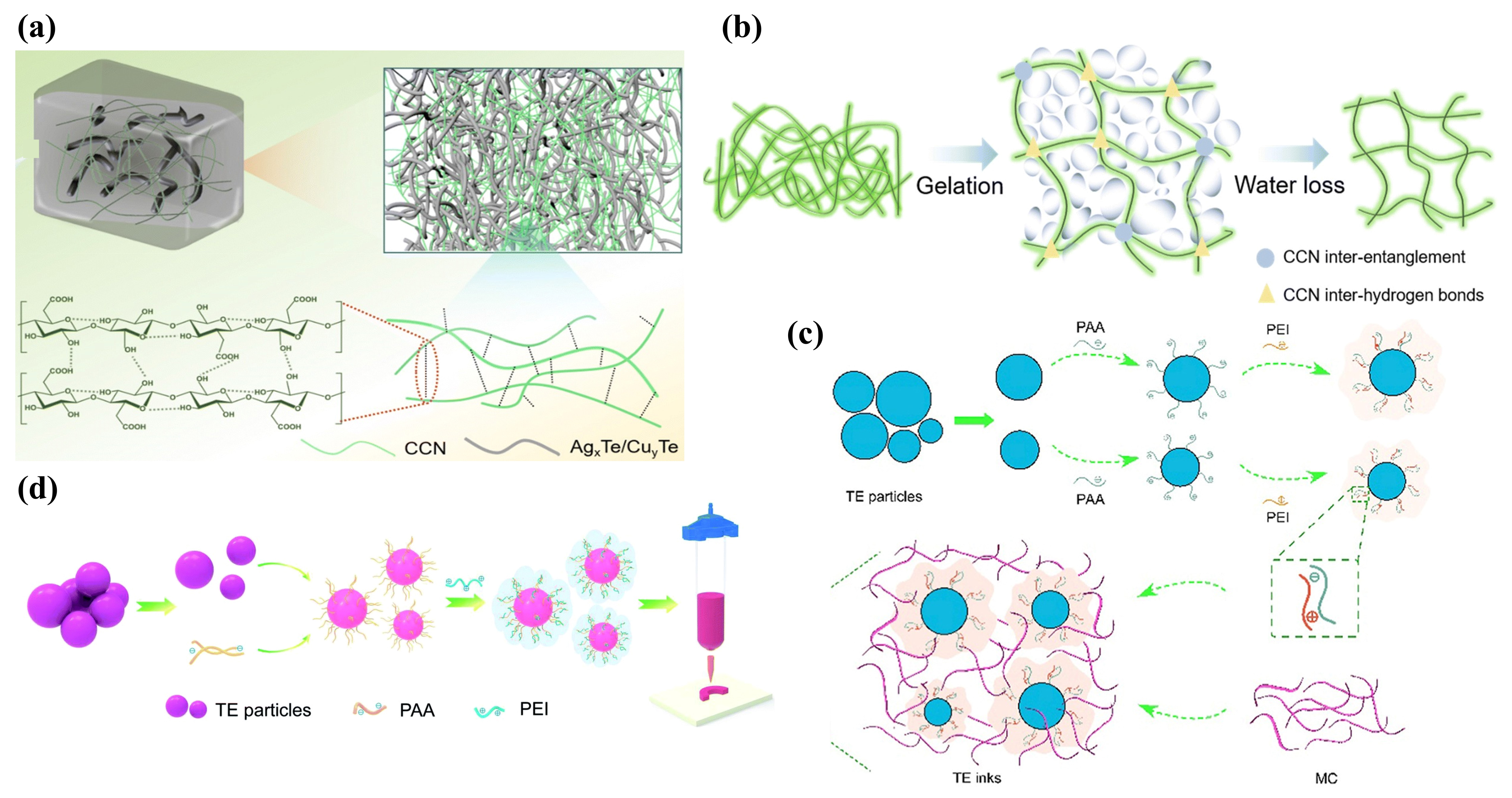
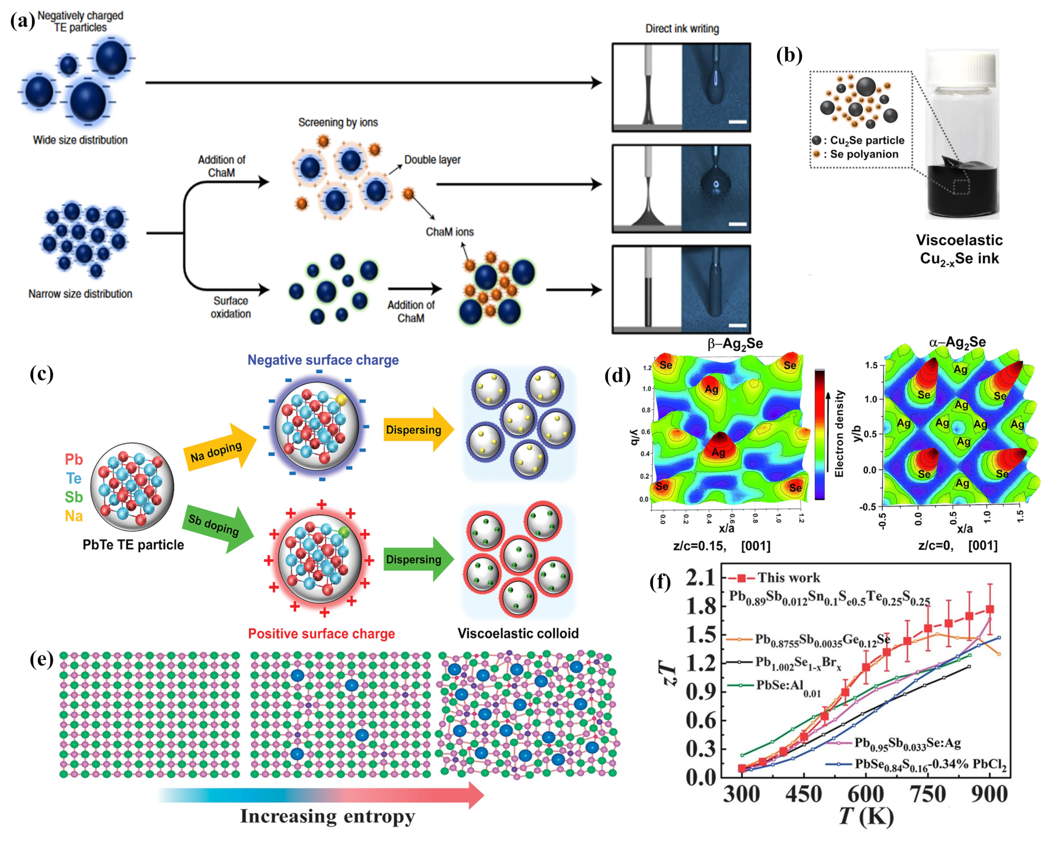
2.1. Optimization of TEG Ink Materials
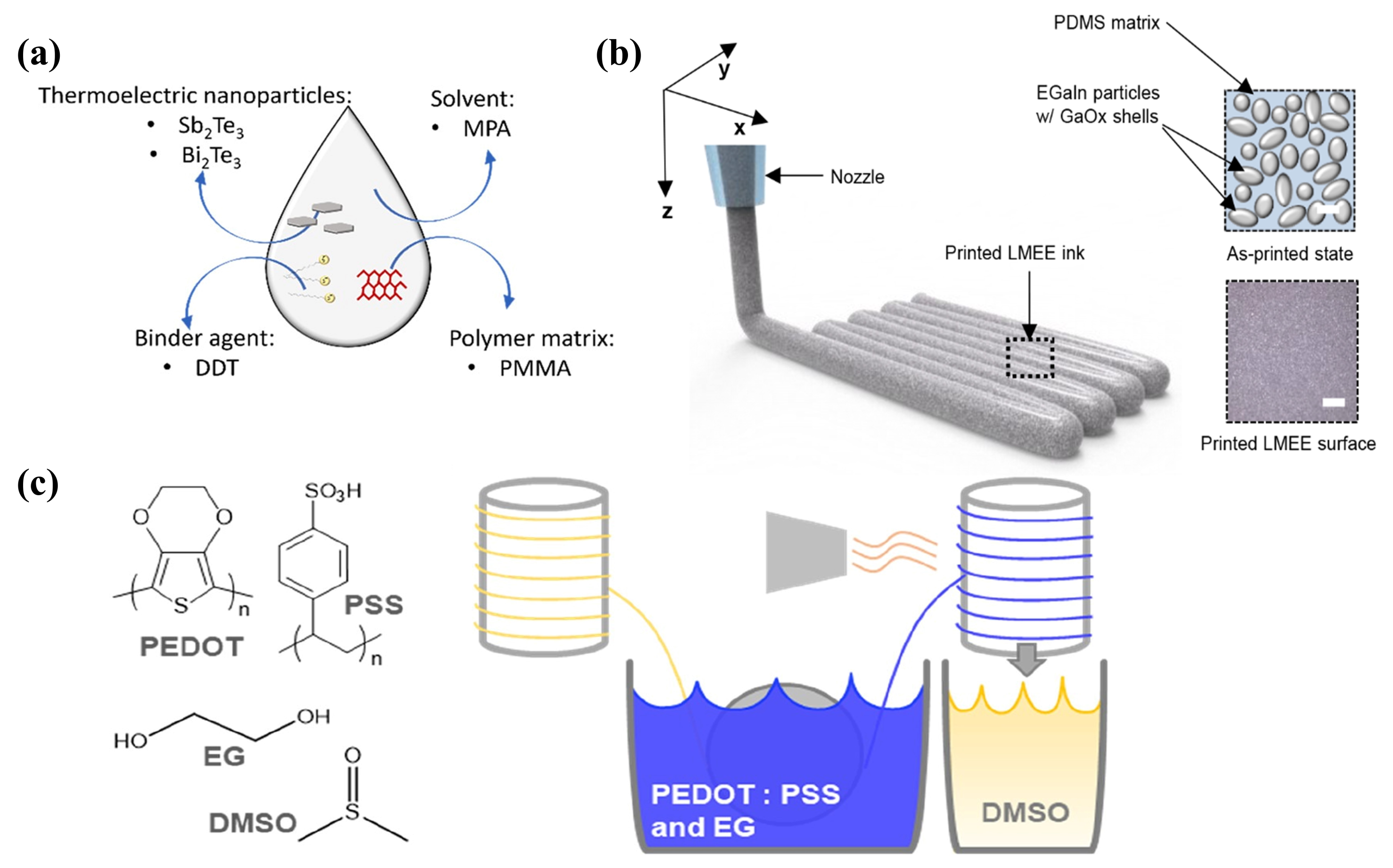
2.1.1. Metal Nanoparticle-Based TE Inks
2.1.2. Polymer-Based TE Inks
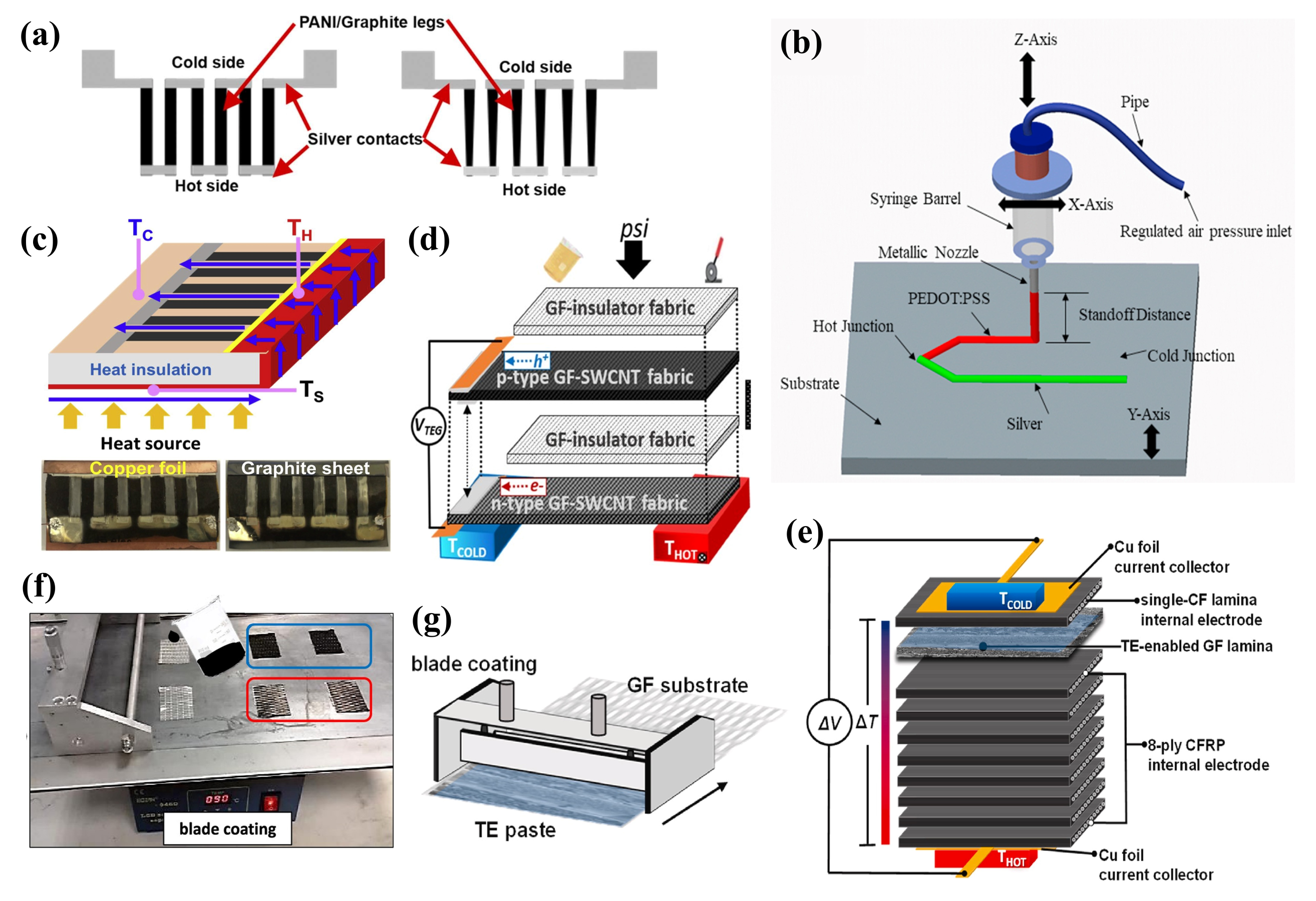
2.1.3. Carbon-Based TE Inks
2.1.4. CQD TE Inks
2.2. TEG Structure Design
2.2.1. Planar Ink-Based TEG Structure
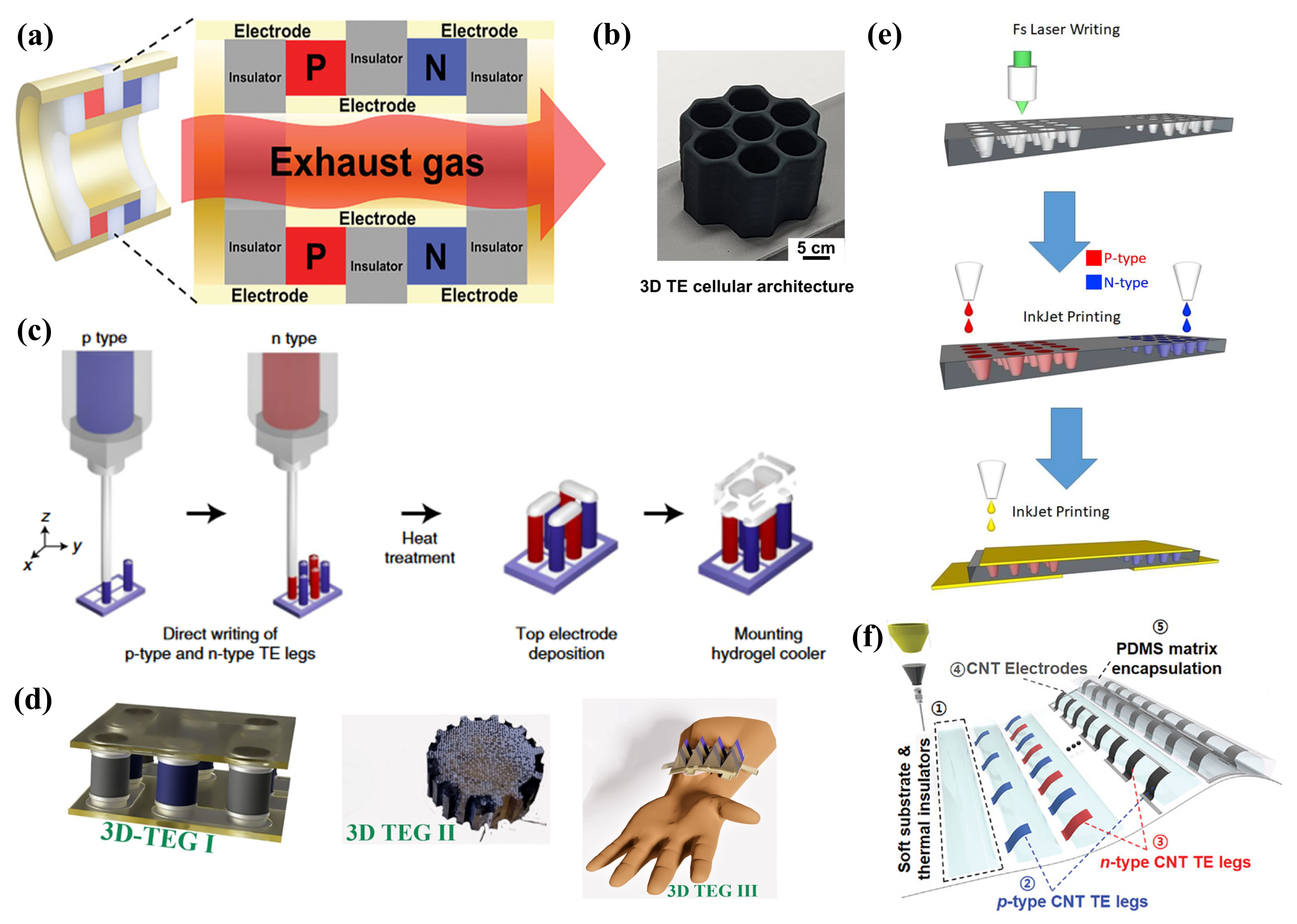
2.2.2. Three-Dimensional Ink-Based TEG Structure
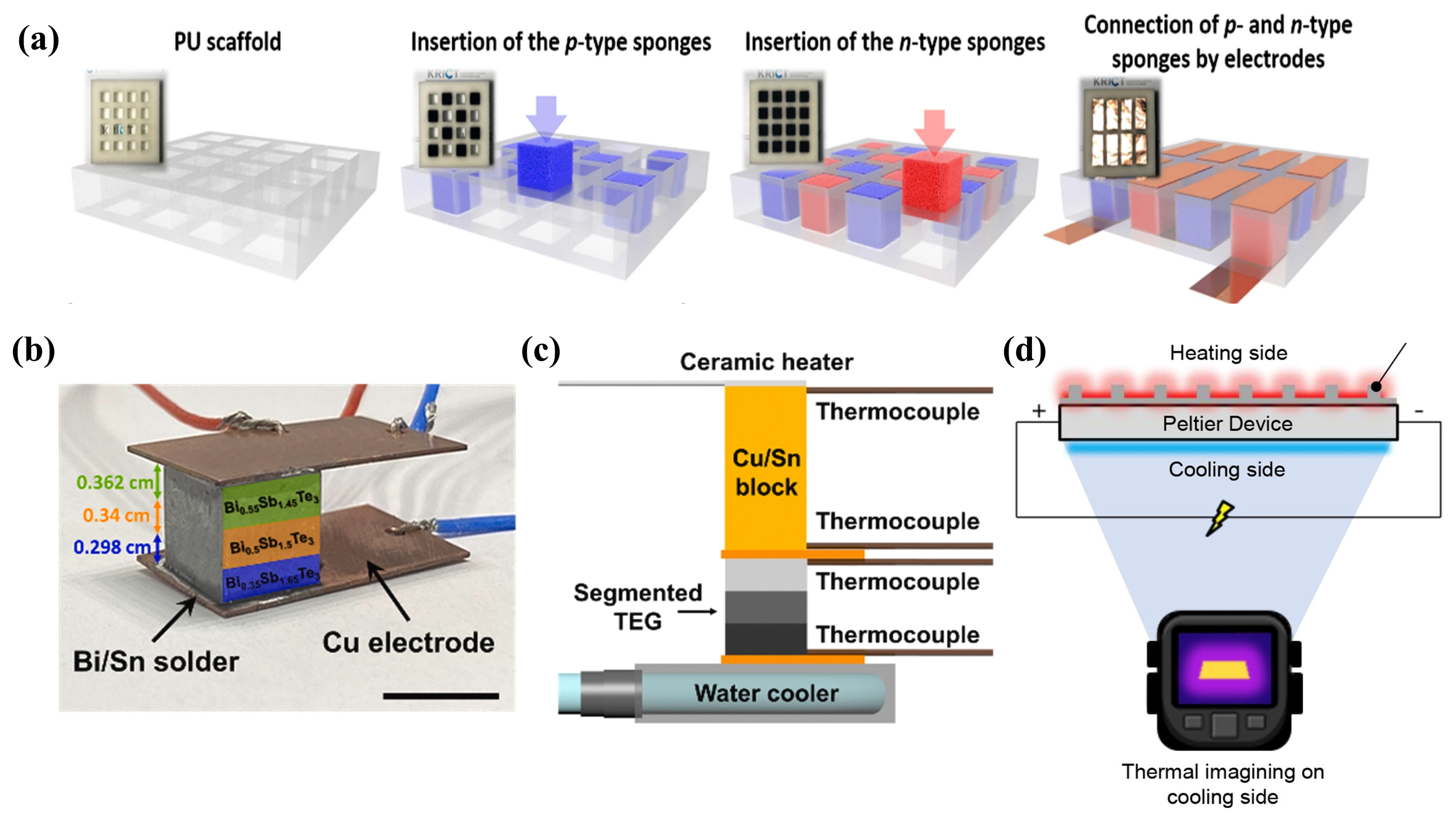
2.2.3. Bulk Ink-Based TEG Structure
2.3. Other Perspectives on TEG
2.3.1. Substrate Protection
2.3.2. Flexibility Enhancement
2.3.3. Novel Ink-Based TEG Fabrication Processes
3. Ink-Based TENGs
3.1. Optimization of TENG Ink Materials
3.1.1. Electrode Conductive Ink
3.1.2. Friction Dielectric Layer Ink

3.1.3. Special Function Inks
3.2. TENG Structure Design
3.2.1. Planar Ink-Based TENG Structure
3.2.2. Three-Dimensional Ink-Based TENG Structure
3.2.3. Pulse Output Ink-Based TENG Structure
3.3. Other Perspectives on TENG
3.3.1. Integration with NFs
3.3.2. Novel Ink-Based TENG Fabrication Processes
4. Other Ink-Based Nanogenerator Technologies
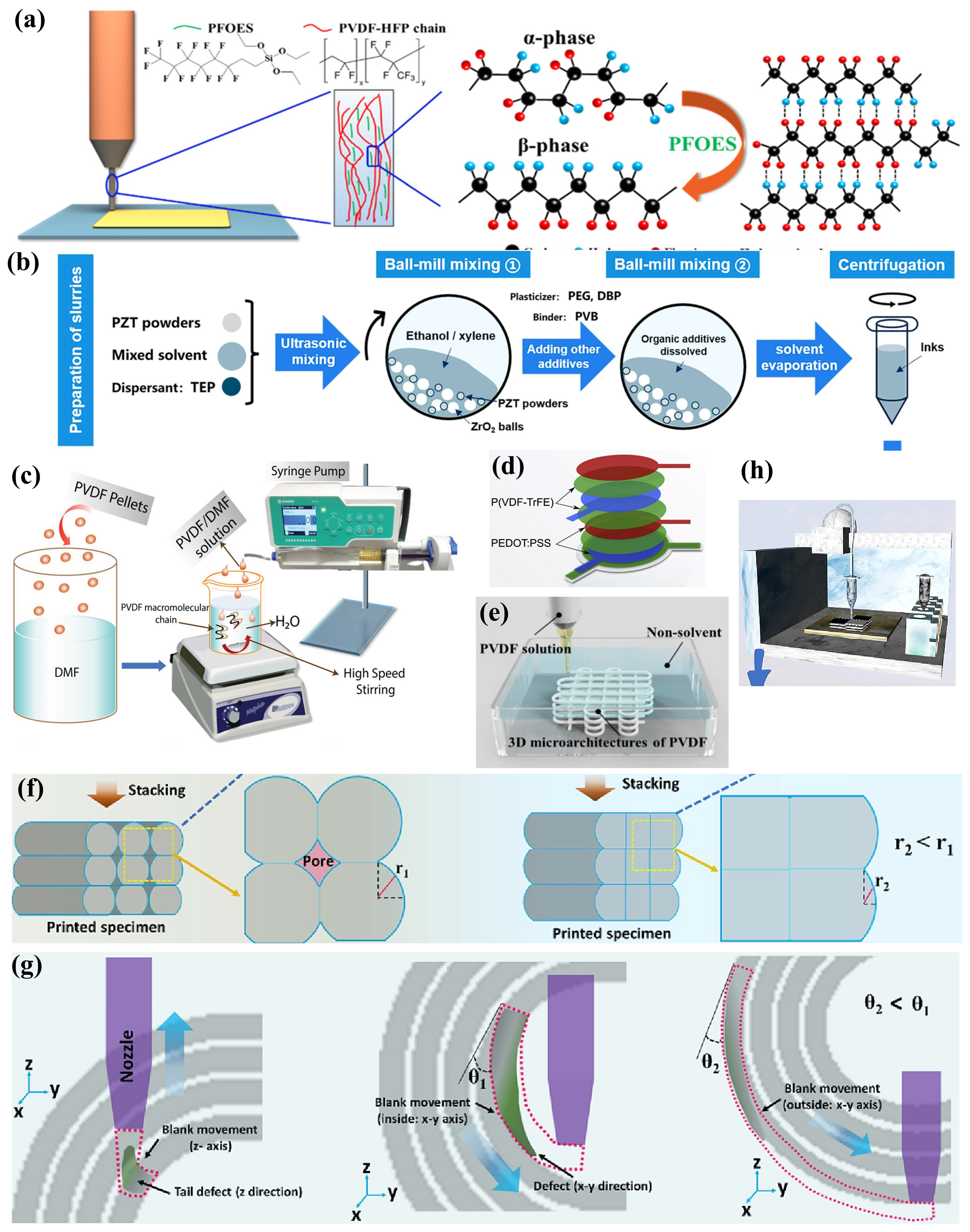
4.1. Ink-Based PENGs
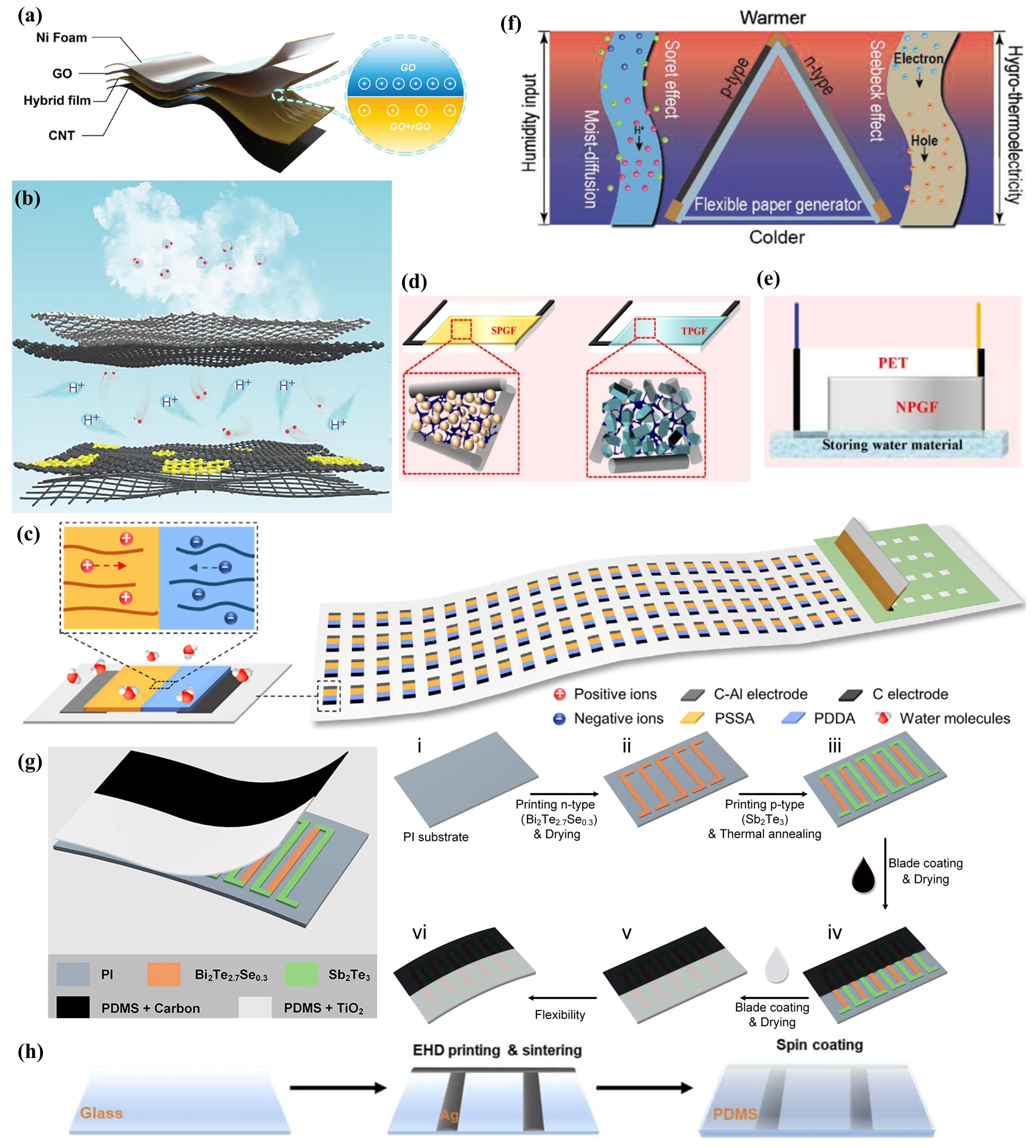
4.2. Ink-Based Moisture-Enabled Nanogenerators
4.3. Ink-Based Hybrid Energy Nanogenerators
5. The Latest Advances in Ink-Based Nanogenerator Applications
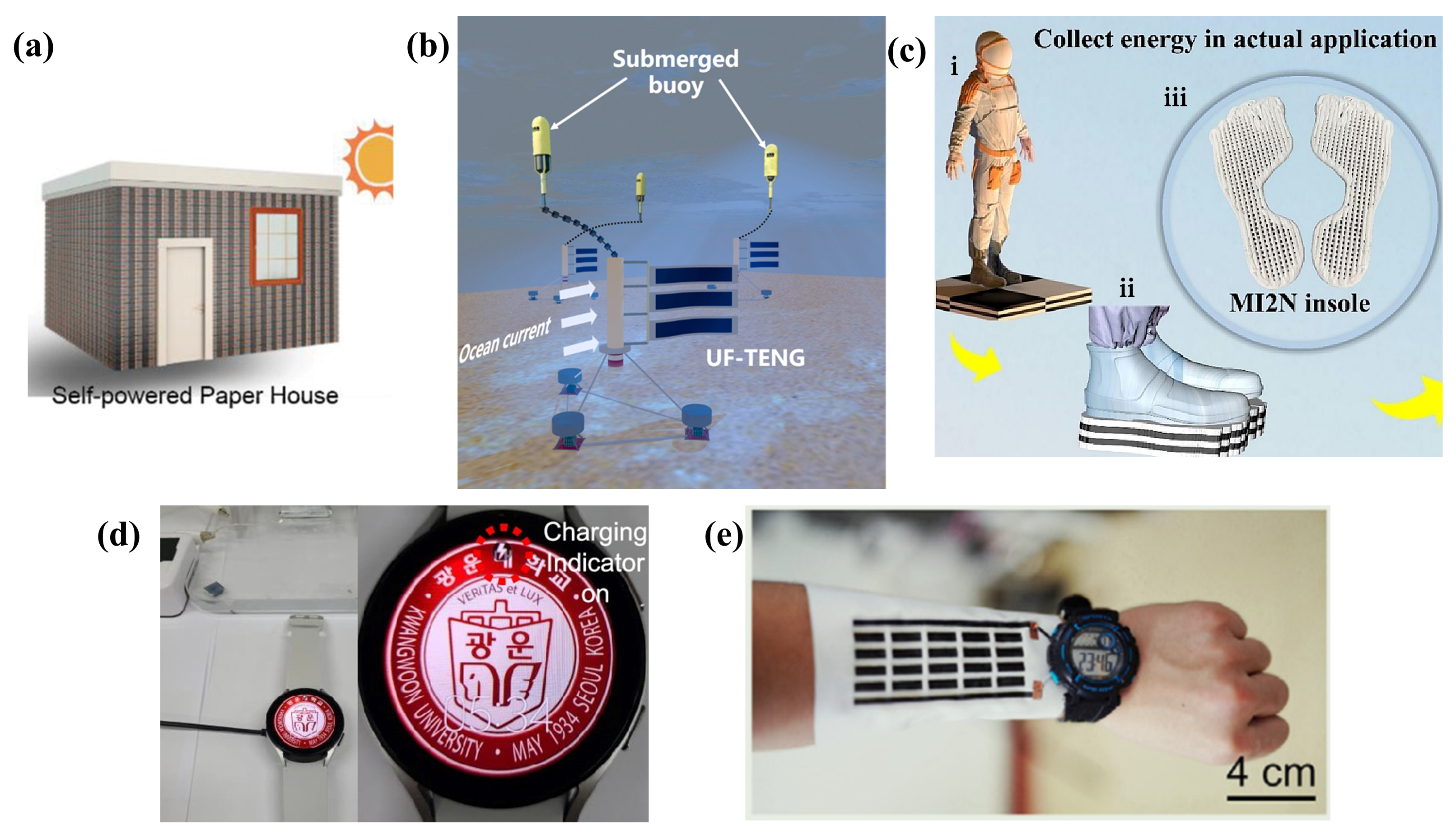
5.1. Power Supply Devices
5.2. Self-Powered Sensing Devices
6. Challenges, Outlook, and Future Perspectives of Ink-Based Nanogenerators
- In the field of ink-based TEGs, significant progress has been made in the long-term stability and good dispersibility of TE inks, but improving the TE performance of materials remains a top priority, especially for n-type organic TE materials. The current performance enhancement of organic ink materials is mostly achieved through the doping of toxic inorganic precious metal NPs. Among these, carbon-based nanocomposite materials and CQD materials show great potential. In terms of structural design, further exploration of efficient 3D heat-collecting structures is warranted, along with the continued enrichment of substrate optimization and protection methods.
- In the field of ink-based TENGs, the electrical performance of conductive inks and dielectric inks should be further improved, and efforts should be made to find corrosion-resistant ink materials or designs that can adapt to complex environments. Special emphasis should be placed on improving the electrical performance of n-type polymer dielectric inks and exploring methods that minimize or eliminate the use of inorganic precious metal NPs. The relative motion of functional layers can also accelerate ink wear to some extent; thus, exploring the potential of self-healing inks is necessary. Structural design can continue to enrich the research on linear micro-surfaces, protruding micro-surfaces, block structures, and even biomimetic microstructures.
- In the field of ink-based PENGs, the active exploration of performance enhancement of PE ink materials through the enrichment of solution-induced -phase PVDF is needed. Moreover, optimizing the stacked structural design remains an effective way to significantly improve performance and deserves active exploration.
- For ink-based MEGs, research is relatively weak, with most studies focusing on carbon-based ink materials. It is necessary to actively expand the range of ink material choices and optimize ink materials. Additionally, exploring efficient water vapor absorption structural designs for energy conversion is essential.
- For ink-based hybrid energy nanogenerators, the active exploration of the synergistic principles and methods of multiple energy conversion effects is required. Additionally, optimizing integration and efficient connection under multiple power generation mechanisms can significantly enhance output performance.
Author Contributions
Funding
Institutional Review Board Statement
Informed Consent Statement
Data Availability Statement
Conflicts of Interest
Abbreviations
| AM | Additive manufacturing |
| BST | BiSbTe |
| BTS | BiTeSe |
| ChaM | Chalcogenometalate |
| ChNC | Chitin nanocrystal |
| CNF | Cellulose nanofiber |
| CNT | Carbon nanotube |
| CZT | CuZnSnS |
| EGaIn | Eutectic gallium-indium |
| FDM | Fused deposition modeling |
| GO | Graphene oxide |
| IoT | The Internet of Things |
| LM | Liquid metal |
| MWCNT | Multi-walled carbon nanotube |
| NR | Nanorod |
| NW | Nanowire |
| PAA | Poly(acrylic acid) |
| PANI | Polyaniline |
| PDMS | Polydimethylsiloxane |
| PE | Piezoelectric |
| PEDOT:PSS | Ppoly(3,4-ethylenedioxythiophene):poly(styrenesulfonate) |
| PEI | Poly(ethyleneimine) |
| PEN | Poly(ethylene naphthalate) |
| PENG | Piezoelectric nanogenerator |
| PET | Polyethylene terephthalate |
| PMMA | Polymethylmethacrylate |
| PTFE | Polytetrafluoroethylene |
| PVA | Polyvinyl alcohol |
| PVDF | Polyvinylidene fluoride |
| rGO | Reduced graphene oxide |
| SMP | Shape memory polymer |
| SWCNT | Single-walled carbon nanotube |
| TE | Thermoelectric |
| TEG | Thermoelectric nanogenerator |
| TENG | Triboelectric nanogenerator |
| TMD | Transition metal dichalcogenide |
References
- Zhao, J.; Xu, Z.; Zhou, Z.; Xi, S.; Xia, Y.; Zhang, Q.; Huang, L.; Mei, L.; Jiang, Y.; Gao, J.; et al. A Safe Flexible Self-Powered Wristband System by Integrating Defective MnO2−x Nanosheet-Based Zinc-Ion Batteries with Perovskite Solar Cells. ACS Nano 2021, 15, 10597–10608. [Google Scholar] [CrossRef] [PubMed]
- Zhou, K.; Zhao, Y.; Sun, X.; Yuan, Z.; Zheng, G.; Dai, K.; Mi, L.; Pan, C.; Liu, C.; Shen, C. Ultra-Stretchable Triboelectric Nanogenerator as High-Sensitive and Self-Powered Electronic Skins for Energy Harvesting and Tactile Sensing. Nano Energy 2020, 70, 104546. [Google Scholar] [CrossRef]
- Liu, Y.; Wang, L.; Zhao, L.; Yu, X.; Zi, Y. Recent Progress on Flexible Nanogenerators toward Self-powered Systems. InfoMat 2020, 2, 318–340. [Google Scholar] [CrossRef]
- Zeng, M.; Zavanelli, D.; Chen, J.; Saeidi-Javash, M.; Du, Y.; LeBlanc, S.; Snyder, G.J.; Zhang, Y. Printing Thermoelectric Inks toward Next-Generation Energy and Thermal Devices. Chem. Soc. Rev. 2022, 51, 485–512. [Google Scholar] [CrossRef] [PubMed]
- Lu, L.; Ding, W.; Liu, J.; Yang, B. Flexible PVDF Based Piezoelectric Nanogenerators. Nano Energy 2020, 78, 105251. [Google Scholar] [CrossRef]
- Xi, Y.; Hua, J.; Shi, Y. Noncontact Triboelectric Nanogenerator for Human Motion Monitoring and Energy Harvesting. Nano Energy 2020, 69, 104390. [Google Scholar] [CrossRef]
- Vera Anaya, D.; He, T.; Lee, C.; Yuce, M.R. Self-Powered Eye Motion Sensor Based on Triboelectric Interaction and near-Field Electrostatic Induction for Wearable Assistive Technologies. Nano Energy 2020, 72, 104675. [Google Scholar] [CrossRef]
- Sun, M.; Li, Z.; Yang, C.; Lv, Y.; Yuan, L.; Shang, C.; Liang, S.; Guo, B.; Liu, Y.; Li, Z.; et al. Nanogenerator-Based Devices for Biomedical Applications. Nano Energy 2021, 89, 106461. [Google Scholar] [CrossRef]
- Tang, N.; Zhou, C.; Qu, D.; Fang, Y.; Zheng, Y.; Hu, W.; Jin, K.; Wu, W.; Duan, X.; Haick, H. A Highly Aligned Nanowire-Based Strain Sensor for Ultrasensitive Monitoring of Subtle Human Motion. Small 2020, 16, 2001363. [Google Scholar] [CrossRef]
- Dong, K.; Peng, X.; Wang, Z.L. Fiber/Fabric-Based Piezoelectric and Triboelectric Nanogenerators for Flexible/Stretchable and Wearable Electronics and Artificial Intelligence. Adv. Mater. 2020, 32, 1902549. [Google Scholar] [CrossRef]
- Wang, H.; Xu, L.; Bai, Y.; Wang, Z.L. Pumping up the Charge Density of a Triboelectric Nanogenerator by Charge-Shuttling. Nat. Commun. 2020, 11, 4203. [Google Scholar] [CrossRef] [PubMed]
- He, J.; Fan, X.; Mu, J.; Wang, C.; Qian, J.; Li, X.; Hou, X.; Geng, W.; Wang, X.; Chou, X. 3D Full-Space Triboelectric-Electromagnetic Hybrid Nanogenerator for High-Efficient Mechanical Energy Harvesting in Vibration System. Energy 2020, 194, 116871. [Google Scholar] [CrossRef]
- Wong, T.H.; Liu, Y.; Li, J.; Yao, K.; Liu, S.; Yiu, C.K.; Huang, X.; Wu, M.; Park, W.; Zhou, J.; et al. Triboelectric Nanogenerator Tattoos Enabled by Epidermal Electronic Technologies. Adv. Funct. Mater. 2022, 32, 2111269. [Google Scholar] [CrossRef]
- Panwisawas, C.; Tang, Y.T.; Reed, R.C. Metal 3D Printing as a Disruptive Technology for Superalloys. Nat. Commun. 2020, 11, 2327. [Google Scholar] [CrossRef] [PubMed]
- Xu, J.; Wang, K.; Sheng, H.; Gao, M.; Zhang, S.; Tan, J. Energy Efficiency Optimization for Ecological 3D Printing Based on Adaptive Multi-Layer Customization. J. Clean. Prod. 2020, 245, 118826. [Google Scholar] [CrossRef]
- Biedermann, M.; Meboldt, M. Computational Design Synthesis of Additive Manufactured Multi-Flow Nozzles. Addit. Manuf. 2020, 35, 101231. [Google Scholar] [CrossRef]
- Zhao, B.; Sivasankar, V.S.; Subudhi, S.K.; Sinha, S.; Dasgupta, A.; Das, S. Applications, Fluid Mechanics, and Colloidal Science of Carbon-Nanotube-Based 3D Printable Inks. Nanoscale 2022, 14, 14858–14894. [Google Scholar] [CrossRef] [PubMed]
- Rakshit, M.; Jana, D.; Banerjee, D. General Strategies to Improve Thermoelectric Performance with an Emphasis on Tin and Germanium Chalcogenides as Thermoelectric Materials. J. Mater. Chem. A 2022, 10, 6872–6926. [Google Scholar] [CrossRef]
- Kim, D.W.; Lee, J.H.; Kim, J.K.; Jeong, U. Material Aspects of Triboelectric Energy Generation and Sensors. NPG Asia Mater. 2020, 12, 6. [Google Scholar] [CrossRef]
- Song, L.; Huang, Z.; Guo, S.; Li, Y.; Wang, Q. Hierarchically Architected Polyvinylidene Fluoride Piezoelectric Foam for Boosted Mechanical Energy Harvesting and Self-Powered Sensor. ACS Appl. Mater. Interfaces 2021, 13, 37252–37261. [Google Scholar] [CrossRef]
- Chen, F.; Zhang, S.; Guan, P.; Xu, Y.; Wan, T.; Lin, C.H.; Li, M.; Wang, C.; Chu, D. High-Performance Flexible Graphene Oxide-Based Moisture-Enabled Nanogenerator via Multilayer Heterojunction Engineering and Power Management System. Small 2023, 2304572. [Google Scholar] [CrossRef] [PubMed]
- Nugraha, M.I.; Sun, B.; Kim, H.; El-Labban, A.; Desai, S.; Chaturvedi, N.; Hou, Y.; Garcia De Arquer, F.P.; Alshareef, H.N.; Sargent, E.H.; et al. Dopant-Assisted Matrix Stabilization Enables Thermoelectric Performance Enhancement in n-Type Quantum Dot Films. ACS Appl. Mater. Interfaces 2021, 13, 18999–19007. [Google Scholar] [CrossRef] [PubMed]
- Wang, Z.; Cui, W.; Yuan, H.; Kang, X.; Zheng, Z.; Qiu, W.; Hu, Q.; Tang, J.; Cui, X. Direct Ink Writing of Bi2Te3-based Thermoelectric Materials Induced by Rheological Design. Mater. Today Energy 2023, 31, 101206. [Google Scholar] [CrossRef]
- Chen, Z.; Lv, H.; Zhang, Q.; Wang, H.; Chen, G. Construction of a Cement–Rebar Nanoarchitecture for a Solution-processed and Flexible Film of a Bi2Te3/CNT Hybrid toward Low Thermal Conductivity and High Thermoelectric Performance. Carbon Energy 2022, 4, 115–128. [Google Scholar] [CrossRef]
- He, Y.; Lin, X.; Feng, Y.; Luo, B.; Liu, M. Carbon Nanotube Ink Dispersed by Chitin Nanocrystals for Thermoelectric Converter for Self-Powering Multifunctional Wearable Electronics. Adv. Sci. 2022, 9, 2204675. [Google Scholar] [CrossRef] [PubMed]
- Chang, P.S.; Liao, C.N. Screen-Printed Flexible Thermoelectric Generator with Directional Heat Collection Design. J. Alloys Compd. 2020, 836, 155471. [Google Scholar] [CrossRef]
- Karalis, G.; Tzounis, L.; Tsirka, K.; Mytafides, C.K.; Voudouris Itskaras, A.; Liebscher, M.; Lambrou, E.; Gergidis, L.N.; Barkoula, N.M.; Paipetis, A.S. Advanced Glass Fiber Polymer Composite Laminate Operating as a Thermoelectric Generator: A Structural Device for Micropower Generation and Potential Large-Scale Thermal Energy Harvesting. ACS Appl. Mater. Interfaces 2021, 13, 24138–24153. [Google Scholar] [CrossRef] [PubMed]
- Lee, J.; Choo, S.; Ju, H.; Hong, J.; Yang, S.E.; Kim, F.; Gu, D.H.; Jang, J.; Kim, G.; Ahn, S.; et al. Doping-Induced Viscoelasticity in PbTe Thermoelectric Inks for 3D Printing of Power-Generating Tubes. Adv. Energy Mater. 2021, 11, 2100190. [Google Scholar] [CrossRef]
- Massetti, M.; Bonfadini, S.; Nava, D.; Butti, M.; Criante, L.; Lanzani, G.; Qiu, L.; Hummelen, J.; Liu, J.; Koster, L.; et al. Fully Direct Written Organic Micro-Thermoelectric Generators Embedded in a Plastic Foil. Nano Energy 2020, 75, 104983. [Google Scholar] [CrossRef]
- Hwang, S.; Jang, D.; Lee, B.; Ryu, Y.S.; Kwak, J.; Kim, H.; Chung, S. All Direct Ink Writing of 3D Compliant Carbon Thermoelectric Generators for High-Energy Conversion Efficiency. Adv. Energy Mater. 2023, 13, 2204171. [Google Scholar] [CrossRef]
- Yang, S.E.; Kim, F.; Ejaz, F.; Lee, G.S.; Ju, H.; Choo, S.; Lee, J.; Kim, G.; Jung, S.H.; Ahn, S.; et al. Composition-Segmented BiSbTe Thermoelectric Generator Fabricated by Multimaterial 3D Printing. Nano Energy 2021, 81, 105638. [Google Scholar] [CrossRef]
- Li, Z.; Li, Y.; Wang, Z.; Wu, P.; Liu, N.; Liu, K.; Gu, Z.; Chen, Y.; Nie, J.; Shao, H.; et al. 3D-printable and Multifunctional Conductive Nanocomposite with Tunable Mechanics Inspired by Sesame Candy. Nano Energy 2023, 108, 108166. [Google Scholar] [CrossRef]
- Yang, C.Y.; Stoeckel, M.A.; Ruoko, T.P.; Wu, H.Y.; Liu, X.; Kolhe, N.B.; Wu, Z.; Puttisong, Y.; Musumeci, C.; Massetti, M.; et al. A High-Conductivity n-Type Polymeric Ink for Printed Electronics. Nat. Commun. 2021, 12, 2354. [Google Scholar] [CrossRef] [PubMed]
- Hedau, B.; Kang, B.C.; Ha, T.J. Enhanced Triboelectric Effects of Self-Poled MoS2-Embedded PVDF Hybrid Nanocomposite Films for Bar-Printed Wearable Triboelectric Nanogenerators. ACS Nano 2022, 16, 18355–18365. [Google Scholar] [CrossRef] [PubMed]
- Yang, J.R.; Lee, C.J.; Chang, C.Y. An Electrostatically Self-Assembled Fluorinated Molecule as a Surface Modification Layer for a High-Performance and Stable Triboelectric Nanogenerator. J. Mater. Chem. A 2021, 9, 4230–4239. [Google Scholar] [CrossRef]
- Li, H.; Dong, X.; Jiang, H.; Qian, R.; Wu, B.; Liu, B.; Jiang, L.; Tang, Y.; Ding, X. Wearable Triboelectric Nanogenerator with Micro-Topping Structures via Material Jet Printing Method. Nano Energy 2023, 114, 108650. [Google Scholar] [CrossRef]
- Cheng, E.; Zhang, Z.; Zhang, G.; Gao, L.; Chen, X.; Bi, X.; Bu, F.; Kong, W.; Yin, H.; Hu, W.; et al. A Triboelectric Nanogenerator Coupled with Internal and External Friction for Gesture Recognition Based on EHD Printing Technology. Nano Energy 2023, 110, 108357. [Google Scholar] [CrossRef]
- Wang, Y.; Liu, X.; Chen, T.; Wang, H.; Zhu, C.; Yu, H.; Song, L.; Pan, X.; Mi, J.; Lee, C.; et al. An Underwater Flag-like Triboelectric Nanogenerator for Harvesting Ocean Current Energy under Extremely Low Velocity Condition. Nano Energy 2021, 90, 106503. [Google Scholar] [CrossRef]
- Zhang, S.; Rana, S.S.; Bhatta, T.; Pradhan, G.B.; Sharma, S.; Song, H.; Jeong, S.; Park, J.Y. 3D Printed Smart Glove with Pyramidal MXene/Ecoflex Composite-Based Toroidal Triboelectric Nanogenerators for Wearable Human-Machine Interaction Applications. Nano Energy 2023, 106, 108110. [Google Scholar] [CrossRef]
- Wang, B.; Gao, M.; Fu, X.; Geng, M.; Liu, Y.; Cheng, N.; Li, J.; Li, L.; Zhang, Z.; Song, Y. 3D Printing Deep-Trap Hierarchical Architecture-Based Non-Contact Sensor for Multi-Direction Motion Monitoring. Nano Energy 2023, 107, 108135. [Google Scholar] [CrossRef]
- Wen, D.L.; Deng, H.T.; Liu, X.; Li, G.K.; Zhang, X.R.; Zhang, X.S. Wearable Multi-Sensing Double-Chain Thermoelectric Generator. Microsyst. Nanoeng. 2020, 6, 68. [Google Scholar] [CrossRef] [PubMed]
- Li, H.; Lim, S. Self-Poled and Transparent Polyvinylidene Fluoride- Co -Hexafluoropropylene-Based Piezoelectric Devices for Printable and Flexible Electronics. Nanoscale 2023, 15, 4581–4590. [Google Scholar] [CrossRef] [PubMed]
- Mishra, H.K.; Gill, A.K.; Gupta, V.; Malik, P.; Sinha, T.K.; Patra, D.; Mandal, D. All Organic Aqueous Processable Piezo-Phototronic Ink for Strain Modulated Photoresponse. Adv. Mater. Technol. 2023, 8, 2201350. [Google Scholar] [CrossRef]
- Li, Z.; Li, J.; Luo, H.; Yuan, X.; Wang, X.; Xiong, H.; Zhang, D. Direct Ink Writing of 3D Piezoelectric Ceramics with Complex Unsupported Structures. J. Eur. Ceram. Soc. 2022, 42, 3841–3847. [Google Scholar] [CrossRef]
- Godard, N.; Allirol, L.; Latour, A.; Glinsek, S.; Gérard, M.; Polesel, J.; Domingues Dos Santos, F.; Defay, E. 1-mW Vibration Energy Harvester Based on a Cantilever with Printed Polymer Multilayers. Cell Rep. Phys. Sci. 2020, 1, 100068. [Google Scholar] [CrossRef]
- Chen, F.; An, Z.; Chen, Y.; Li, Y.; Liu, X.; Chen, N.; Ru, Y.; Gao, D. Multi-Material 3D Printing of Piezoelectric and Triboelectric Integrated Nanogenerators with Voxel Structure. Chem. Eng. J. 2023, 471, 144770. [Google Scholar] [CrossRef]
- He, T.; Wang, H.; Lu, B.; Guang, T.; Yang, C.; Huang, Y.; Cheng, H.; Qu, L. Fully Printed Planar Moisture-Enabled Electric Generator Arrays for Scalable Function Integration. Joule 2023, 7, 935–951. [Google Scholar] [CrossRef]
- Shakeel, M.; Rehman, K.; Ahmad, S.; Amin, M.; Iqbal, N.; Khan, A. A Low-Cost Printed Organic Thermoelectric Generator for Low-Temperature Energy Harvesting. Renew. Energy 2021, 167, 853–860. [Google Scholar] [CrossRef]
- Jouhara, H.; Żabnieńska-Góra, A.; Khordehgah, N.; Doraghi, Q.; Ahmad, L.; Norman, L.; Axcell, B.; Wrobel, L.; Dai, S. Thermoelectric Generator (TEG) Technologies and Applications. Int. J. Thermofluids 2021, 9, 100063. [Google Scholar] [CrossRef]
- Hasan, M.N.; Wahid, H.; Nayan, N.; Mohamed Ali, M.S. Inorganic Thermoelectric Materials: A Review. Int. J. Energy Res. 2020, 44, 6170–6222. [Google Scholar] [CrossRef]
- Sargolzaeiaval, Y.; Padmanabhan Ramesh, V.; Neumann, T.V.; Misra, V.; Vashaee, D.; Dickey, M.D.; Öztürk, M.C. Flexible Thermoelectric Generators for Body Heat Harvesting—Enhanced Device Performance Using High Thermal Conductivity Elastomer Encapsulation on Liquid Metal Interconnects. Appl. Energy 2020, 262, 114370. [Google Scholar] [CrossRef]
- Liang, L.; Wang, M.; Wang, X.; Peng, P.; Liu, Z.; Chen, G.; Sun, G. Initiating a Stretchable, Compressible, and Wearable Thermoelectric Generator by a Spiral Architecture with Ternary Nanocomposites for Efficient Heat Harvesting. Adv. Funct. Mater. 2022, 32, 2111435. [Google Scholar] [CrossRef]
- Bharti, M.; Singh, A.; Singh, B.P.; Dhakate, S.R.; Saini, G.; Bhattacharya, S.; Debnath, A.; Muthe, K.; Aswal, D. Free-Standing Flexible Multiwalled Carbon Nanotubes Paper for Wearable Thermoelectric Power Generator. J. Power Sources 2020, 449, 227493. [Google Scholar] [CrossRef]
- Lee, T.; Lee, J.W.; Park, K.T.; Kim, J.S.; Park, C.R.; Kim, H. Nanostructured Inorganic Chalcogenide-Carbon Nanotube Yarn Having a High Thermoelectric Power Factor at Low Temperature. ACS Nano 2021, 15, 13118–13128. [Google Scholar] [CrossRef] [PubMed]
- Wu, B.; Guo, Y.; Hou, C.; Zhang, Q.; Li, Y.; Wang, H. From Carbon Nanotubes to Highly Adaptive and Flexible High-Performance Thermoelectric Generators. Nano Energy 2021, 89, 106487. [Google Scholar] [CrossRef]
- Ding, D.; Sun, F.; Xia, F.; Tang, Z. A High-Performance and Flexible Thermoelectric Generator Based on the Solution-Processed Composites of Reduced Graphene Oxide Nanosheets and Bismuth Telluride Nanoplates. Nanoscale Adv. 2020, 2, 3244–3251. [Google Scholar] [CrossRef] [PubMed]
- Zhang, Y.; Liu, Y.; Xing, C.; Zhang, T.; Li, M.; Pacios, M.; Yu, X.; Arbiol, J.; Llorca, J.; Cadavid, D.; et al. Tin Selenide Molecular Precursor for the Solution Processing of Thermoelectric Materials and Devices. ACS Appl. Mater. Interfaces 2020, 12, 27104–27111. [Google Scholar] [CrossRef] [PubMed]
- Guan, X.; Feng, W.; Wang, X.; Venkatesh, R.; Ouyang, J. Significant Enhancement in the Seebeck Coefficient and Power Factor of P-Type Poly(3,4-Ethylenedioxythiophene):Poly(Styrenesulfonate) through the Incorporation of n-Type MXene. ACS Appl. Mater. Interfaces 2020, 12, 13013–13020. [Google Scholar] [CrossRef] [PubMed]
- Zhou, J.; Liu, X.; Shao, Z.; Shen, T.; Yu, H.; Yang, X.; You, H.; Chen, D.; Liu, C.; Liu, Y. Enhanced Thermoelectric Properties of Coated Vanadium Oxynitride Nanoparticles/PEDOT:PSS Hybrid Films. ACS Appl. Mater. Interfaces 2023, 15, 9953–9961. [Google Scholar] [CrossRef]
- Iravani, S.; Varma, R.S. Green Synthesis, Biomedical and Biotechnological Applications of Carbon and Graphene Quantum Dots. A Review. Environ. Chem. Lett. 2020, 18, 703–727. [Google Scholar] [CrossRef]
- Nugraha, M.I.; Indriyati, I.; Primadona, I.; Gedda, M.; Timuda, G.E.; Iskandar, F.; Anthopoulos, T.D. Recent Progress in Colloidal Quantum Dot Thermoelectrics. Adv. Mater. 2023, 35, 2210683. [Google Scholar] [CrossRef] [PubMed]
- Wei, T.R.; Qiu, P.; Zhao, K.; Shi, X.; Chen, L. Ag2Q-based (Q = S, Se, Te) silver chalcogenide thermoelectric materials. Adv. Mater. 2023, 35, 2110236. [Google Scholar] [CrossRef] [PubMed]
- Deng, L.; Liu, Y.; Zhang, Y.; Wang, S.; Gao, P. Organic Thermoelectric Materials: Niche Harvester of Thermal Energy. Adv. Funct. Mater. 2023, 33, 2210770. [Google Scholar] [CrossRef]
- Liu, M.; Yazdani, N.; Yarema, M.; Jansen, M.; Wood, V.; Sargent, E.H. Colloidal Quantum Dot Electronics. Nat. Electron. 2021, 4, 548–558. [Google Scholar] [CrossRef]
- Chen, W.Y.; Shi, X.L.; Zou, J.; Chen, Z.G. Wearable Fiber-Based Thermoelectrics from Materials to Applications. Nano Energy 2021, 81, 105684. [Google Scholar] [CrossRef]
- Shen, Y.; Han, X.; Zhang, P.; Chen, X.; Yang, X.; Liu, D.; Yang, X.; Zheng, X.; Chen, H.; Zhang, K.; et al. Review on Fiber-Based Thermoelectrics: Materials, Devices, and Textiles. Adv. Fiber Mater. 2023, 5, 1105–1140. [Google Scholar] [CrossRef]
- Mallick, M.M.; Rösch, A.G.; Franke, L.; Gall, A.; Ahmad, S.; Geßwein, H.; Mazilkin, A.; Kübel, C.; Lemmer, U. New Frontier in Printed Thermoelectrics: Formation of β-Ag 2 Se through Thermally Stimulated Dissociative Adsorption Leads to High ZT. J. Mater. Chem. A 2020, 8, 16366–16375. [Google Scholar] [CrossRef]
- Monga, D.; Sharma, S.; Shetti, N.P.; Basu, S.; Reddy, K.R.; Aminabhavi, T.M. Advances in Transition Metal Dichalcogenide-Based Two-Dimensional Nanomaterials. Mater. Today Chem. 2021, 19, 100399. [Google Scholar] [CrossRef]
- Kirubasankar, B.; Won, Y.S.; Adofo, L.A.; Choi, S.H.; Kim, S.M.; Kim, K.K. Atomic and Structural Modifications of Two-Dimensional Transition Metal Dichalcogenides for Various Advanced Applications. Chem. Sci. 2022, 13, 7707–7738. [Google Scholar] [CrossRef]
- Li, W.; Poudel, B.; Nozariasbmarz, A.; Sriramdas, R.; Zhu, H.; Kang, H.B.; Priya, S. Bismuth Telluride/Half-Heusler Segmented Thermoelectric Unicouple Modules Provide 12% Conversion Efficiency. Adv. Energy Mater. 2020, 10, 2001924. [Google Scholar] [CrossRef]
- Li, D.; Gong, Y.; Chen, Y.; Lin, J.; Khan, Q.; Zhang, Y.; Li, Y.; Zhang, H.; Xie, H. Recent Progress of Two-Dimensional Thermoelectric Materials. Nano-Micro Lett. 2020, 12, 36. [Google Scholar] [CrossRef] [PubMed]
- Hu, S.; Ren, Z.; Djurišić, A.B.; Rogach, A.L. Metal Halide Perovskites as Emerging Thermoelectric Materials. ACS Energy Lett. 2021, 6, 3882–3905. [Google Scholar] [CrossRef]
- Dong, J.; Suwardi, A.; Tan, X.Y.; Jia, N.; Saglik, K.; Ji, R.; Wang, X.; Zhu, Q.; Xu, J.; Yan, Q. Challenges and Opportunities in Low-Dimensional Thermoelectric Nanomaterials. Mater. Today 2023, 66, 137–157. [Google Scholar] [CrossRef]
- Park, H.; Kim, J.Y.; Oh, J.Y.; Lee, T.I. Long-Term Stable NbSe2 Nanosheet Aqueous Ink for Printable Electronics. Appl. Surf. Sci. 2020, 504, 144342. [Google Scholar] [CrossRef]
- Dai, C.; Li, B.; Li, J.; Zhao, B.; Wu, R.; Ma, H.; Duan, X. Controllable Synthesis of NiS and NiS2 Nanoplates by Chemical Vapor Deposition. Nano Res. 2020, 13, 2506–2511. [Google Scholar] [CrossRef]
- Mao, J.; Iocozzia, J.; Huang, J.; Meng, K.; Lai, Y.; Lin, Z. Graphene Aerogels for Efficient Energy Storage and Conversion. Energy Environ. Sci. 2018, 11, 772–799. [Google Scholar] [CrossRef]
- Pei, Y.; Heinz, N.A.; Snyder, G.J. Alloying to Increase the Band Gap for Improving Thermoelectric Properties of Ag2Te. J. Mater. Chem. 2011, 21, 18256. [Google Scholar] [CrossRef]
- Syafiq, U.; Isotta, E.; Ataollahi, N.; Lohani, K.; Luong, S.; Trifiletti, V.; Fenwick, O.; Scardi, P. Facile and Low-Cost Fabrication of Cu/Zn/Sn-Based Ternary and Quaternary Chalcogenides Thermoelectric Generators. ACS Appl. Energy Mater. 2022, 5, 5909–5918. [Google Scholar] [CrossRef]
- Lee, H.; Koo, M.; Park, C.; Patel, M.; Han, H.; Park, T.H.; Kumar, P.; Koh, W.G.; Park, C. Zwitterion-Assisted Transition Metal Dichalcogenide Nanosheets for Scalable and Biocompatible Inkjet Printing. Nano Res. 2020, 13, 2726–2734. [Google Scholar] [CrossRef]
- Adilbekova, B.; Lin, Y.; Yengel, E.; Faber, H.; Harrison, G.; Firdaus, Y.; El-Labban, A.; Anjum, D.H.; Tung, V.; Anthopoulos, T.D. Liquid Phase Exfoliation of MoS2 and WS2 in Aqueous Ammonia and Their Application in Highly Efficient Organic Solar Cells. J. Mater. Chem. C 2020, 8, 5259–5264. [Google Scholar] [CrossRef]
- Du, J.; Zhang, B.; Jiang, M.; Zhang, Q.; Zhang, K.; Liu, Y.; Wang, L.; Jiang, W. Inkjet Printing Flexible Thermoelectric Devices Using Metal Chalcogenide Nanowires. Adv. Funct. Mater. 2023, 33, 2213564. [Google Scholar] [CrossRef]
- Zhang, L.; Chen, C.; Zhou, J.; Yang, G.; Wang, J.; Liu, D.; Chen, Z.; Lei, W. Solid Phase Exfoliation for Producing Dispersible Transition Metal Dichalcogenides Nanosheets. Adv. Funct. Mater. 2020, 30, 2004139. [Google Scholar] [CrossRef]
- Wan, X.; Miao, X.; Yao, J.; Wang, S.; Shao, F.; Xiao, S.; Zhan, R.; Chen, K.; Zeng, X.; Gu, X.; et al. In Situ Ultrafast and Patterned Growth of Transition Metal Dichalcogenides from Inkjet-Printed Aqueous Precursors. Adv. Mater. 2021, 33, 2100260. [Google Scholar] [CrossRef] [PubMed]
- Karger, L.; Synnatschke, K.; Settele, S.; Hofstetter, Y.J.; Nowack, T.; Zaumseil, J.; Vaynzof, Y.; Backes, C. The Role of Additives in Suppressing the Degradation of Liquid-Exfoliated WS 2 Monolayers. Adv. Mater. 2021, 33, 2102883. [Google Scholar] [CrossRef] [PubMed]
- Rao, T.; Wang, H.; Zeng, Y.J.; Guo, Z.; Zhang, H.; Liao, W. Phase Transitions and Water Splitting Applications of 2D Transition Metal Dichalcogenides and Metal Phosphorous Trichalcogenides. Adv. Sci. 2021, 8, 2002284. [Google Scholar] [CrossRef] [PubMed]
- Varghese, T.; Dun, C.; Kempf, N.; Saeidi-Javash, M.; Karthik, C.; Richardson, J.; Hollar, C.; Estrada, D.; Zhang, Y. Flexible Thermoelectric Devices of Ultrahigh Power Factor by Scalable Printing and Interface Engineering. Adv. Funct. Mater. 2020, 30, 1905796. [Google Scholar] [CrossRef]
- Jung, S.h.; Kim, K.T.; Lee, G.S.; Sun, J.Y.; Kim, D.W.; Eom, Y.S.; Yang, D.Y.; Yu, J.; Park, J.M.; Hyeon, D.Y.; et al. Synergistically Improved Thermoelectric Energy Harvesting of Edge-Oxidized-Graphene-Bridged N-Type Bismuth Telluride Thick Films. ACS Appl. Mater. Interfaces 2021, 13, 5125–5132. [Google Scholar] [CrossRef] [PubMed]
- Zhao, K.; Liu, C.; Shao, T.; Fan, Y.; Chen, R.; Pan, X. Enhanced Thermoelectric Performance of Bi2Te3 by Carbon Nanotubes and Silicate Aerogel Co-Doping toward Ocean Energy Harvesting. Mater. Today Sustain. 2023, 23, 100476. [Google Scholar] [CrossRef]
- Zhu, C.; Wang, J.; Luo, F.; Zhang, S.; Wang, J.; Zhang, Y.; Liu, H.; Sun, Z. Enhanced Thermoelectric Performance of GeTe-Based Composites Incorporated with Fe Nanoparticles. ACS Appl. Mater. Interfaces 2022, 14, 38854–38864. [Google Scholar] [CrossRef]
- Feng, J.; Zhu, W.; Zhang, Z.; Cao, L.; Yu, Y.; Deng, Y. Enhanced Electrical Transport Properties via Defect Control for Screen-Printed Bi2Te3 Films over a Wide Temperature Range. ACS Appl. Mater. Interfaces 2020, 12, 16630–16638. [Google Scholar] [CrossRef]
- Park, S.H.; Jo, S.; Kwon, B.; Kim, F.; Ban, H.W.; Lee, J.E.; Gu, D.H.; Lee, S.H.; Hwang, Y.; Kim, J.S.; et al. High-Performance Shape-Engineerable Thermoelectric Painting. Nat. Commun. 2016, 7, 13403. [Google Scholar] [CrossRef]
- Sarwar, N.; Choi, S.H.; Dastgeer, G.; Humayoun, U.B.; Kumar, M.; Nawaz, A.; Jeong, D.I.; Zaidi, S.F.A.; Yoon, D.H. Synthesis of Citrate-Capped Copper Nanoparticles: A Low Temperature Sintering Approach for the Fabrication of Oxidation Stable Flexible Conductive Film. Appl. Surf. Sci. 2021, 542, 148609. [Google Scholar] [CrossRef]
- Liu, D.; Zhao, Y.; Yan, Z.; Zhang, Z.; Zhang, Y.; Shi, P.; Xue, C. Screen-Printed Flexible Thermoelectric Device Based on Hybrid Silver Selenide/PVP Composite Films. Nanomaterials 2021, 11, 2042. [Google Scholar] [CrossRef]
- Kim, K.T.; Choi, S.Y.; Shin, E.H.; Moon, K.S.; Koo, H.Y.; Lee, G.G.; Ha, G.H. The Influence of CNTs on the Thermoelectric Properties of a CNT/Bi2Te3 Composite. Carbon 2013, 52, 541–549. [Google Scholar] [CrossRef]
- Jang, E.; Banerjee, P.; Huang, J.; Madan, D. High Performance Scalable and Cost-Effective Thermoelectric Devices Fabricated Using Energy Efficient Methods and Naturally Occuring Materials. Appl. Energy 2021, 294, 117006. [Google Scholar] [CrossRef]
- Kim, F.; Yang, S.E.; Ju, H.; Choo, S.; Lee, J.; Kim, G.; Jung, S.h.; Kim, S.; Cha, C.; Kim, K.T.; et al. Direct Ink Writing of Three-Dimensional Thermoelectric Microarchitectures. Nat. Electron. 2021, 4, 579–587. [Google Scholar] [CrossRef]
- del-Mazo-Barbara, L.; Ginebra, M.P. Rheological Characterisation of Ceramic Inks for 3D Direct Ink Writing: A Review. J. Eur. Ceram. Soc. 2021, 41, 18–33. [Google Scholar] [CrossRef]
- Huang, K.; Elsayed, H.; Franchin, G.; Colombo, P. Embedded Direct Ink Writing of Freeform Ceramic Components. Appl. Mater. Today 2021, 23, 101005. [Google Scholar] [CrossRef]
- Wu, B.; Geng, J.; Lin, Y.; Hou, C.; Zhang, Q.; Li, Y.; Wang, H. Hydrogel-Based Printing Strategy for High-Performance Flexible Thermoelectric Generators. Nanoscale 2022, 14, 16857–16864. [Google Scholar] [CrossRef]
- Wang, Z.; Cui, W.; Yuan, H.; Kang, X.; Zheng, Z.; Chen, L.; Hu, Q.; Qiu, W.; Tang, J.; Cui, X. Direct Ink Writing of High-Performance Bi2Te3-Based Thermoelectric Materials Using Quasi-Inorganic Inks and Interface Engineering. J. Mater. Chem. A 2022, 10, 12921–12927. [Google Scholar] [CrossRef]
- Schlisske, S.; Rosenauer, C.; Rödlmeier, T.; Giringer, K.; Michels, J.J.; Kremer, K.; Lemmer, U.; Morsbach, S.; Daoulas, K.C.; Hernandez-Sosa, G. Ink Formulation for Printed Organic Electronics: Investigating Effects of Aggregation on Structure and Rheology of Functional Inks Based on Conjugated Polymers in Mixed Solvents. Adv. Mater. Technol. 2021, 6, 2000335. [Google Scholar] [CrossRef]
- Kim, F.; Kwon, B.; Eom, Y.; Lee, J.E.; Park, S.; Jo, S.; Park, S.H.; Kim, B.S.; Im, H.J.; Lee, M.H.; et al. 3D Printing of Shape-Conformable Thermoelectric Materials Using All-Inorganic Bi2Te3-based Inks. Nat. Energy 2018, 3, 301–309. [Google Scholar] [CrossRef]
- Choo, S.; Ejaz, F.; Ju, H.; Kim, F.; Lee, J.; Yang, S.E.; Kim, G.; Kim, H.; Jo, S.; Baek, S.; et al. Cu2Se-based Thermoelectric Cellular Architectures for Efficient and Durable Power Generation. Nat. Commun. 2021, 12, 3550. [Google Scholar] [CrossRef] [PubMed]
- Jiang, B.; Yu, Y.; Cui, J.; Liu, X.; Xie, L.; Liao, J.; Zhang, Q.; Huang, Y.; Ning, S.; Jia, B.; et al. High-Entropy-Stabilized Chalcogenides with High Thermoelectric Performance. Science 2021, 371, 830–834. [Google Scholar] [CrossRef]
- Zhang, M.; Cao, X.; Wen, M.; Chen, C.; Wen, Q.; Fu, Q.; Deng, H. Highly Electrical Conductive PEDOT:PSS/SWCNT Flexible Thermoelectric Films Fabricated by a High-Velocity Non-solvent Turbulent Secondary Doping Approach. ACS Appl. Mater. Interfaces 2023, 15, 10947–10957. [Google Scholar] [CrossRef]
- Li, H.; Zong, Y.; Ding, Q.; Han, W.; Li, X. Paper-Based Thermoelectric Generator Based on Multi-Walled Carbon Nanotube/Carboxylated Nanocellulose. J. Power Sources 2021, 500, 229992. [Google Scholar] [CrossRef]
- Li, J.; Huckleby, A.B.; Zhang, M. Polymer-Based Thermoelectric Materials: A Review of Power Factor Improving Strategies. J. Mater. 2022, 8, 204–220. [Google Scholar] [CrossRef]
- Panigrahy, S.; Kandasubramanian, B. Polymeric Thermoelectric PEDOT: PSS & Composites: Synthesis, Progress, and Applications. Eur. Polym. J. 2020, 132, 109726. [Google Scholar] [CrossRef]
- Prunet, G.; Pawula, F.; Fleury, G.; Cloutet, E.; Robinson, A.; Hadziioannou, G.; Pakdel, A. A Review on Conductive Polymers and Their Hybrids for Flexible and Wearable Thermoelectric Applications. Mater. Today Phys. 2021, 18, 100402. [Google Scholar] [CrossRef]
- Deng, W.; Deng, L.; Li, Z.; Zhang, Y.; Chen, G. Synergistically Boosting Thermoelectric Performance of PEDOT:PSS/SWCNT Composites via the Ion-Exchange Effect and Promoting SWCNT Dispersion by the Ionic Liquid. ACS Appl. Mater. Interfaces 2021, 13, 12131–12140. [Google Scholar] [CrossRef]
- Xu, Y.; Jia, Y.; Liu, P.; Jiang, Q.; Hu, D.; Ma, Y. Poly(3,4-Ethylenedioxythiophene) (PEDOT) as Promising Thermoelectric Materials and Devices. Chem. Eng. J. 2021, 404, 126552. [Google Scholar] [CrossRef]
- Wang, Y.; Pang, H.; Guo, Q.; Tsujii, N.; Baba, T.; Baba, T.; Mori, T. Flexible n-Type Abundant Chalcopyrite/PEDOT:PSS/Graphene Hybrid Film for Thermoelectric Device Utilizing Low-Grade Heat. ACS Appl. Mater. Interfaces 2021, 13, 51245–51254. [Google Scholar] [CrossRef] [PubMed]
- Meng, Q.; Song, H.; Du, Y.; Ding, Y.; Cai, K. Facile Preparation of Poly(3,4-Ethylenedioxythiophene): Poly(Styrenesulfonate)/Ag2Te Nanorod Composite Films for Flexible Thermoelectric Generator. J. Mater. 2021, 7, 302–309. [Google Scholar] [CrossRef]
- Yoon, S.E.; Park, J.; Kwon, J.E.; Lee, S.Y.; Han, J.M.; Go, C.Y.; Choi, S.; Kim, K.C.; Seo, H.; Kim, J.H.; et al. Improvement of Electrical Conductivity in Conjugated Polymers through Cascade Doping with Small-Molecular Dopants. Adv. Mater. 2020, 32, 2005129. [Google Scholar] [CrossRef] [PubMed]
- Liang, L.; Wang, X.; Wang, M.; Liu, Z.; Chen, G.; Sun, G. Flexible Poly(3,4-Ethylenedioxythiophene)-Tosylate/SWCNT Composite Films with Ultrahigh Electrical Conductivity for Thermoelectric Energy Harvesting. Compos. Commun. 2021, 25, 100701. [Google Scholar] [CrossRef]
- Lu, Y.; Yu, Z.D.; Un, H.I.; Yao, Z.F.; You, H.Y.; Jin, W.; Li, L.; Wang, Z.Y.; Dong, B.W.; Barlow, S.; et al. Persistent Conjugated Backbone and Disordered Lamellar Packing Impart Polymers with Efficient n-Doping and High Conductivities. Adv. Mater. 2021, 33, 2005946. [Google Scholar] [CrossRef] [PubMed]
- Lu, Y.; Yu, Z.D.; Liu, Y.; Ding, Y.F.; Yang, C.Y.; Yao, Z.F.; Wang, Z.Y.; You, H.Y.; Cheng, X.F.; Tang, B.; et al. The Critical Role of Dopant Cations in Electrical Conductivity and Thermoelectric Performance of N-Doped Polymers. J. Am. Chem. Soc. 2020, 142, 15340–15348. [Google Scholar] [CrossRef] [PubMed]
- Nandihalli, N.; Liu, C.J.; Mori, T. Polymer Based Thermoelectric Nanocomposite Materials and Devices: Fabrication and Characteristics. Nano Energy 2020, 78, 105186. [Google Scholar] [CrossRef]
- Serrano-Claumarchirant, J.F.; Hamawandi, B.; Ergül, A.B.; Cantarero, A.; Gómez, C.M.; Priyadarshi, P.; Neophytou, N.; Toprak, M.S. Thermoelectric Inks and Power Factor Tunability in Hybrid Films through All Solution Process. ACS Appl. Mater. Interfaces 2022, 14, 19295–19303. [Google Scholar] [CrossRef]
- Won, P.; Valentine, C.S.; Zadan, M.; Pan, C.; Vinciguerra, M.; Patel, D.K.; Ko, S.H.; Walker, L.M.; Majidi, C. 3D Printing of Liquid Metal Embedded Elastomers for Soft Thermal and Electrical Materials. ACS Appl. Mater. Interfaces 2022, 14, 55028–55038. [Google Scholar] [CrossRef]
- Darabi, S.; Hummel, M.; Rantasalo, S.; Rissanen, M.; Öberg Månsson, I.; Hilke, H.; Hwang, B.; Skrifvars, M.; Hamedi, M.M.; Sixta, H.; et al. Green Conducting Cellulose Yarns for Machine-Sewn Electronic Textiles. ACS Appl. Mater. Interfaces 2020, 12, 56403–56412. [Google Scholar] [CrossRef] [PubMed]
- Yang, X.; Cui, J.; Xue, K.; Fu, Y.; Li, H.; Yang, H. Thermal Conductivity and Thermoelectric Properties in 3D Macroscopic Pure Carbon Nanotube Materials. Nanotechnol. Rev. 2021, 10, 178–186. [Google Scholar] [CrossRef]
- Mytafides, C.K.; Tzounis, L.; Karalis, G.; Formanek, P.; Paipetis, A.S. Fully Printed and Flexible Carbon Nanotube-Based Thermoelectric Generator Capable for High-Temperature Applications. J. Power Sources 2021, 507, 230323. [Google Scholar] [CrossRef]
- Sun, X.; Wang, Y.; Li, K.; Wang, J.; Dai, X.; Chong, D.; Yan, J.; Wang, H. Anisotropic electrical conductivity and isotropic Seebeck coefficient feature induced high thermoelectric power factor >1800 μW m−1 K−2 in MWCNT films. Adv. Funct. Mater. 2022, 32, 2203080. [Google Scholar] [CrossRef]
- Fan, J.; Wang, X.; Liu, F.; Chen, Z.; Chen, G. N-Type Flexible Films and a Thermoelectric Generator of Single-Walled Carbon Nanotube-Grafted Tin Selenide Nanocrystal Composites. ACS Appl. Mater. Interfaces 2021, 13, 30731–30738. [Google Scholar] [CrossRef] [PubMed]
- Zhang, Y.; Deng, L.; Lv, H.; Chen, G. Toward Improved Trade-off between Thermoelectric and Mechanical Performances in Polycarbonate/Single-Walled Carbon Nanotube Composite Films. npj Flex. Electron. 2020, 4, 26. [Google Scholar] [CrossRef]
- Zhang, L.; Jin, J.; Huang, S.; Tan, B.; Luo, J.; Wang, D.; Liu, D.; Wang, L. Cross-Conjugated Spiro Molecules and Single-Walled Carbon Nanotubes Composite for High-Performance Organic Thermoelectric Materials and Generators. Chem. Eng. J. 2021, 426, 131859. [Google Scholar] [CrossRef]
- Hicks, L.; Harman, T.; Sun, X.; Dresselhaus, M. Experimental study of the effect of quantum-well structures on the thermoelectric figure of merit. Phys. Rev. B 1996, 53, R10493. [Google Scholar] [CrossRef] [PubMed]
- Xu, Y.; Gan, Z.; Zhang, S.C. Enhanced Thermoelectric Performance and Anomalous Seebeck Effects in Topological Insulators. Phys. Rev. Lett. 2014, 112, 226801. [Google Scholar] [CrossRef]
- Li, P.; Shi, J.; Wu, X.; Li, J.; Hu, L.; Liu, F.; Li, Y.; Ao, W.; Zhang, C. Interfacial Engineering of Solution-Processed Bi2Te3-based Thermoelectric Nanocomposites via Graphene Addition and Liquid-Phase-Sintering Process. Chem. Eng. J. 2022, 440, 135882. [Google Scholar] [CrossRef]
- Yang, G.; Sang, L.; Li, M.; Kazi Nazrul Islam, S.M.; Yue, Z.; Liu, L.; Li, J.; Mitchell, D.R.; Ye, N.; Wang, X. Enhancing the Thermoelectric Performance of Polycrystalline SnSe by Decoupling Electrical and Thermal Transport through Carbon Fiber Incorporation. ACS Appl. Mater. Interfaces 2020, 12, 12910–12918. [Google Scholar] [CrossRef] [PubMed]
- Li, H.; Liang, Y.; Liu, Y.; Liu, S.; Li, P.; He, C. Engineering Doping Level for Enhanced Thermoelectric Performance of Carbon Nanotubes/Polyaniline Composites. Compos. Sci. Technol. 2021, 210, 108797. [Google Scholar] [CrossRef]
- Qin, Y.; Zhang, Q.; Chen, G. Organic Borate Doped Carbon Nanotube for Enhancement of Thermoelectric Performance. Carbon 2021, 182, 742–748. [Google Scholar] [CrossRef]
- Wei, L.; Huang, H.; Gao, C.; Liu, D.; Wang, L. Novel Butterfly-Shaped Organic Semiconductor and Single-Walled Carbon Nanotube Composites for High Performance Thermoelectric Generators. Mater. Horiz. 2021, 8, 1207–1215. [Google Scholar] [CrossRef] [PubMed]
- Jin, L.; Sun, T.; Zhao, W.; Wang, L.; Jiang, W. Durable and Washable Carbon Nanotube-Based Fibers toward Wearable Thermoelectric Generators Application. J. Power Sources 2021, 496, 229838. [Google Scholar] [CrossRef]
- Kim, S.; Mo, J.H.; Jang, K.S. High-Performance n-Type Carbon Nanotubes Doped by Oxidation of Neighboring Sb2Te3 for a Flexible Thermoelectric Generator. ACS Appl. Mater. Interfaces 2020, 12, 43778–43784. [Google Scholar] [CrossRef] [PubMed]
- Liu, Y.; Villalva, D.R.; Sharma, A.; Haque, M.A.; Baran, D. Molecular Doping of a Naphthalene Diimide–Bithiophene Copolymer and SWCNTs for n-Type Thermoelectric Composites. ACS Appl. Mater. Interfaces 2021, 13, 411–418. [Google Scholar] [CrossRef] [PubMed]
- Mytafides, C.K.; Tzounis, L.; Karalis, G.; Formanek, P.; Paipetis, A.S. High-Power All-Carbon Fully Printed and Wearable SWCNT-Based Organic Thermoelectric Generator. ACS Appl. Mater. Interfaces 2021, 13, 11151–11165. [Google Scholar] [CrossRef]
- Nayak, R.; Shetty, P.; M, S.; Rao, A.; Rao, K. Formulation of New Screen Printable PANI and PANI/Graphite Based Inks: Printing and Characterization of Flexible Thermoelectric Generators. Energy 2022, 238, 121680. [Google Scholar] [CrossRef]
- Liu, Y.; Calcabrini, M.; Yu, Y.; Lee, S.; Chang, C.; David, J.; Ghosh, T.; Spadaro, M.C.; Xie, C.; Cojocaru-Mirédin, O.; et al. Defect Engineering in Solution-Processed Polycrystalline SnSe Leads to High Thermoelectric Performance. ACS Nano 2022, 16, 78–88. [Google Scholar] [CrossRef]
- García De Arquer, F.P.; Talapin, D.V.; Klimov, V.I.; Arakawa, Y.; Bayer, M.; Sargent, E.H. Semiconductor Quantum Dots: Technological Progress and Future Challenges. Science 2021, 373, eaaz8541. [Google Scholar] [CrossRef] [PubMed]
- Li, S.; Hou, Y.; Zhang, S.; Gong, Y.; Siddique, S.; Li, D.; Fang, J.; Nan, P.; Ge, B.; Tang, G. Realizing High Thermoelectric Performance in Magnetic Field-Assisted Solution Synthesized Nanoporous SnSe Integrated with Quantum Dots. Chem. Eng. J. 2023, 451, 138637. [Google Scholar] [CrossRef]
- Rösch, A.G.; Gall, A.; Aslan, S.; Hecht, M.; Franke, L.; Mallick, M.M.; Penth, L.; Bahro, D.; Friderich, D.; Lemmer, U. Fully Printed Origami Thermoelectric Generators for Energy-Harvesting. npj Flex. Electron. 2021, 5, 1. [Google Scholar] [CrossRef]
- Kishore, R.A.; Nozariasbmarz, A.; Poudel, B.; Priya, S. High-Performance Thermoelectric Generators for Field Deployments. ACS Appl. Mater. Interfaces 2020, 12, 10389–10401. [Google Scholar] [CrossRef] [PubMed]
- Selvam, C.; Manikandan, S.; Krishna, N.V.; Lamba, R.; Kaushik, S.; Mahian, O. Enhanced Thermal Performance of a Thermoelectric Generator with Phase Change Materials. Int. Commun. Heat Mass Transf. 2020, 114, 104561. [Google Scholar] [CrossRef]
- Chen, X.; Zhou, Z.; Lin, Y.H.; Nan, C. Thermoelectric Thin Films: Promising Strategies and Related Mechanism on Boosting Energy Conversion Performance. J. Mater. 2020, 6, 494–512. [Google Scholar] [CrossRef]
- Yu, Y.; Zhu, W.; Wang, Y.; Zhu, P.; Peng, K.; Deng, Y. Towards High Integration and Power Density: Zigzag-type Thin-Film Thermoelectric Generator Assisted by Rapid Pulse Laser Patterning Technique. Appl. Energy 2020, 275, 115404. [Google Scholar] [CrossRef]
- Shittu, S.; Li, G.; Zhao, X.; Ma, X. Review of Thermoelectric Geometry and Structure Optimization for Performance Enhancement. Appl. Energy 2020, 268, 115075. [Google Scholar] [CrossRef]
- Wang, P.; Wang, B.; Wang, K.; Gao, R.; Xi, L. An Analytical Model for Performance Prediction and Optimization of Thermoelectric Generators with Varied Leg Cross-Sections. Int. J. Heat Mass Transf. 2021, 174, 121292. [Google Scholar] [CrossRef]
- El Oualid, S.; Kogut, I.; Benyahia, M.; Geczi, E.; Kruck, U.; Kosior, F.; Masschelein, P.; Candolfi, C.; Dauscher, A.; Koenig, J.D.; et al. High Power Density Thermoelectric Generators with Skutterudites. Adv. Energy Mater. 2021, 11, 2100580. [Google Scholar] [CrossRef]
- Nayak, R.; Shetty, P.; M, S.; Rao, A.; Rao, K.M.; K, G.; Mangavati, S. Enhancement of Power Factor of Screen Printed Polyaniline/Graphite Based Flexible Thermoelectric Generator by Structural Modifications. J. Alloys Compd. 2022, 922, 166298. [Google Scholar] [CrossRef]
- Karalis, G.; Tzounis, L.; Tsirka, K.; Mytafides, C.K.; Liebscher, M.; Paipetis, A.S. Carbon Fiber/Epoxy Composite Laminates as through-Thickness Thermoelectric Generators. Compos. Sci. Technol. 2022, 220, 109291. [Google Scholar] [CrossRef]
- Padmanabhan Ramesh, V.; Sargolzaeiaval, Y.; Neumann, T.; Misra, V.; Vashaee, D.; Dickey, M.D.; Ozturk, M.C. Flexible Thermoelectric Generator with Liquid Metal Interconnects and Low Thermal Conductivity Silicone Filler. npj Flex. Electron. 2021, 5, 5. [Google Scholar] [CrossRef]
- Ge, Y.; Lin, Y.; He, Q.; Wang, W.; Chen, J.; Huang, S.M. Geometric Optimization of Segmented Thermoelectric Generators for Waste Heat Recovery Systems Using Genetic Algorithm. Energy 2021, 233, 121220. [Google Scholar] [CrossRef]
- Karthikeyan, V.; Surjadi, J.U.; Wong, J.C.; Kannan, V.; Lam, K.H.; Chen, X.; Lu, Y.; Roy, V.A. Wearable and Flexible Thin Film Thermoelectric Module for Multi-Scale Energy Harvesting. J. Power Sources 2020, 455, 227983. [Google Scholar] [CrossRef]
- Li, W.; Nozariasbmarz, A.; Kishore, R.A.; Kang, H.B.; Dettor, C.; Zhu, H.; Poudel, B.; Priya, S. Conformal High-Power-Density Half-Heusler Thermoelectric Modules: A Pathway toward Practical Power Generators. ACS Appl. Mater. Interfaces 2021, 13, 53935–53944. [Google Scholar] [CrossRef]
- Bandyopadhyay, A.; Zhang, Y.; Bose, S. Recent Developments in Metal Additive Manufacturing. Curr. Opin. Chem. Eng. 2020, 28, 96–104. [Google Scholar] [CrossRef] [PubMed]
- Mallick, M.M.; Franke, L.; Rösch, A.G.; Lemmer, U. Shape-Versatile 3D Thermoelectric Generators by Additive Manufacturing. ACS Energy Lett. 2021, 6, 85–91. [Google Scholar] [CrossRef]
- Wei, S.; Liu, L.; Huang, X.; Zhang, Y.; Liu, F.; Deng, L.; Bilotti, E.; Chen, G. Flexible and Foldable Films of SWCNT Thermoelectric Composites and an S-Shape Thermoelectric Generator with a Vertical Temperature Gradient. ACS Appl. Mater. Interfaces 2022, 14, 5973–5982. [Google Scholar] [CrossRef]
- Kim, J.; Bae, E.J.; Kang, Y.H.; Lee, C.; Cho, S.Y. Elastic Thermoelectric Sponge for Pressure-Induced Enhancement of Power Generation. Nano Energy 2020, 74, 104824. [Google Scholar] [CrossRef]
- Majee, S.; Karlsson, M.C.F.; Wojcik, P.J.; Sawatdee, A.; Mulla, M.Y.; Alvi, N.U.H.; Dyreklev, P.; Beni, V.; Nilsson, D. Low Temperature Chemical Sintering of Inkjet-Printed Zn Nanoparticles for Highly Conductive Flexible Electronic Components. npj Flex. Electron. 2021, 5, 14. [Google Scholar] [CrossRef]
- Hwang, T.Y.; Choi, Y.; Song, Y.; Eom, N.S.A.; Kim, S.; Cho, H.B.; Myung, N.V.; Choa, Y.H. A Noble Gas Sensor Platform: Linear Dense Assemblies of Single-Walled Carbon Nanotubes (LACNTs) in a Multi-Layered Ceramic/Metal Electrode System (MLES). J. Mater. Chem. C 2018, 6, 972–979. [Google Scholar] [CrossRef]
- Lu, X.; Lu, W.; Gao, J.; Liu, Y.; Huang, J.; Yan, P.; Fan, Y.; Jiang, W. Processing High-Performance Thermoelectric Materials in a Green Way: A Proof of Concept in Cold Sintered PbTe0.94Se0.06. ACS Appl. Mater. Interfaces 2022, 14, 37937–37946. [Google Scholar] [CrossRef] [PubMed]
- Xie, K.; Gupta, M.C. Thermoelectric Properties of SiGe Thin Films Prepared by Laser Sintering of Nanograin Powders. J. Alloys Compd. 2020, 820, 153182. [Google Scholar] [CrossRef]
- Nozariasbmarz, A.; Saparamadu, U.; Li, W.; Kang, H.B.; Dettor, C.; Zhu, H.; Poudel, B.; Priya, S. High-Performance Half-Heusler Thermoelectric Devices through Direct Bonding Technique. J. Power Sources 2021, 493, 229695. [Google Scholar] [CrossRef]
- Mallick, M.M.; Franke, L.; Rösch, A.G.; Geßwein, H.; Long, Z.; Eggeler, Y.M.; Lemmer, U. High Figure-of-Merit Telluride-Based Flexible Thermoelectric Films through Interfacial Modification via Millisecond Photonic-Curing for Fully Printed Thermoelectric Generators. Adv. Sci. 2022, 9, 2202411. [Google Scholar] [CrossRef] [PubMed]
- Zhang, X.; Hou, Y.; Yang, Y.; Wang, Z.; Liang, X.; He, Q.; Xu, Y.; Sun, X.; Ma, H.; Liang, J.; et al. Stamp-Like Energy Harvester and Programmable Information Encrypted Display Based on Fully Printable Thermoelectric Devices. Adv. Mater. 2023, 35, 2207723. [Google Scholar] [CrossRef] [PubMed]
- Dong, Z.; Liu, H.; Yang, X.; Fan, J.; Bi, H.; Wang, C.; Zhang, Y.; Luo, C.; Chen, X.; Wu, X. Facile Fabrication of Paper-Based Flexible Thermoelectric Generator. npj Flex. Electron. 2021, 5, 6. [Google Scholar] [CrossRef]
- Baek, S.; Ban, H.W.; Jeong, S.; Heo, S.H.; Gu, D.H.; Choi, W.; Choo, S.; Park, Y.E.; Yoo, J.; Choi, M.K.; et al. Generalised Optical Printing of Photocurable Metal Chalcogenides. Nat. Commun. 2022, 13, 5262. [Google Scholar] [CrossRef]
- Jacob, S.; Delatouche, B.; Péré, D.; Ullah Khan, Z.; Ledoux, M.J.; Crispin, X.; Chmielowski, R. High-Performance Flexible Thermoelectric Modules Based on High Crystal Quality Printed TiS2/Hexylamine. Sci. Technol. Adv. Mater. 2021, 22, 907–916. [Google Scholar] [CrossRef]
- Zhou, X.; Lee, P.S. Three Dimensional Printed Nanogenerators. EcoMat 2021, 3, e12098. [Google Scholar] [CrossRef]
- Guo, B.; Liang, G.; Yu, S.; Wang, Y.; Zhi, C.; Bai, J. 3D Printing of Reduced Graphene Oxide Aerogels for Energy Storage Devices: A Paradigm from Materials and Technologies to Applications. Energy Storage Mater. 2021, 39, 146–165. [Google Scholar] [CrossRef]
- Li, H.; Wang, S.; Dong, X.; Ding, X.; Sun, Y.; Tang, H.; Lu, Y.; Tang, Y.; Wu, X. Recent Advances on Ink-Based Printing Techniques for Triboelectric Nanogenerators: Printable Inks, Printing Technologies and Applications. Nano Energy 2022, 101, 107585. [Google Scholar] [CrossRef]
- Bai, Z.; Xu, Y.; Zhang, Z.; Zhu, J.; Gao, C.; Zhang, Y.; Jia, H.; Guo, J. Highly Flexible, Porous Electroactive Biocomposite as Attractive Tribopositive Material for Advancing High-Performance Triboelectric Nanogenerator. Nano Energy 2020, 75, 104884. [Google Scholar] [CrossRef]
- Zhu, Y.; Chen, C.; Tian, M.; Chen, Y.; Yang, Y.; Gao, S. Self-Powered Electro-Fenton Degradation System Using Oxygen-Containing Functional Groups-Rich Biomass-Derived Carbon Catalyst Driven by 3D Printed Flexible Triboelectric Nanogenerator. Nano Energy 2021, 83, 105720. [Google Scholar] [CrossRef]
- Yang, G.; Wu, H.; Li, Y.; Wang, D.; Song, Y.; Zhou, Y.; Hao, J.; Zi, Y.; Wang, Z.; Zhou, G. Direct Ink Writing of Fluoropolymer/CNT-based Superhydrophobic and Corrosion-Resistant Electrodes for Droplet Energy Harvesters and Self-Powered Electronic Skins. Nano Energy 2021, 86, 106095. [Google Scholar] [CrossRef]
- Wen, D.; Ying, G.; Liu, L.; Li, Y.; Sun, C.; Hu, C.; Zhao, Y.; Ji, Z.; Zhang, J.; Wang, X. Direct Inkjet Printing of Flexible MXene/Graphene Composite Films for Supercapacitor Electrodes. J. Alloys Compd. 2022, 900, 163436. [Google Scholar] [CrossRef]
- Kassem, O.; Barnier, V.; Nasreldin, M.; Reslan, J.; Aoufi, A.; Ravichandran, A.; Sao-joao, S.; Hoummada, K.; Charai, A.; Rieu, M.; et al. Selective Growth of Graphene-Confined Inkjet-Printed Sn Nanoparticles on Plastic Using Intense Pulsed Light Annealing. ACS Appl. Mater. Interfaces 2023, 15, 30663–30673. [Google Scholar] [CrossRef] [PubMed]
- Wu, W.; Guo, N.; Zhang, Y.; Liu, G.; Yu, L.; Ma, X.; Li, W.; Chen, M. The Fabrication, Properties, and Application of a Printed Green Ag NWs-Based Flexible Electrode and Circuit. ACS Appl. Mater. Interfaces 2023, 15, 14643–14653. [Google Scholar] [CrossRef]
- Arief, I.; Zimmermann, P.; Hait, S.; Park, H.; Ghosh, A.K.; Janke, A.; Chattopadhyay, S.; Nagel, J.; Heinrich, G.; Wießner, S.; et al. Elastomeric Microwell-Based Triboelectric Nanogenerators by in Situ Simultaneous Transfer-Printing. Mater. Horiz. 2022, 9, 1468–1478. [Google Scholar] [CrossRef]
- Li, H.; Fang, X.; Li, R.; Liu, B.; Tang, H.; Ding, X.; Xie, Y.; Zhou, R.; Zhou, G.; Tang, Y. All-Printed Soft Triboelectric Nanogenerator for Energy Harvesting and Tactile Sensing. Nano Energy 2020, 78, 105288. [Google Scholar] [CrossRef]
- Huang, L.B.; Han, J.C.; Chen, S.; Sun, Z.; Dai, X.; Ge, P.; Zhao, C.H.; Zheng, Q.Q.; Sun, F.C.; Hao, J. 4D-printed Self-Recovered Triboelectric Nanogenerator for Energy Harvesting and Self-Powered Sensor. Nano Energy 2021, 84, 105873. [Google Scholar] [CrossRef]
- Huang, T.; Liu, W.; Su, C.; Li, Y.y.; Sun, J. Direct Ink Writing of Conductive Materials for Emerging Energy Storage Systems. Nano Res. 2022, 15, 6091–6111. [Google Scholar] [CrossRef]
- Htwe, Y.; Mariatti, M. Printed Graphene and Hybrid Conductive Inks for Flexible, Stretchable, and Wearable Electronics: Progress, Opportunities, and Challenges. J. Sci. Adv. Mater. Devices 2022, 7, 100435. [Google Scholar] [CrossRef]
- Zhu, G.; Ren, P.; Yang, J.; Hu, J.; Dai, Z.; Chen, H.; Li, Y.; Li, Z. Self-Powered and Multi-Mode Flexible Sensing Film with Patterned Conductive Network for Wireless Monitoring in Healthcare. Nano Energy 2022, 98, 107327. [Google Scholar] [CrossRef]
- Du, J.; Yang, X.; Duan, J.; Wang, Y.; Tang, Q. Tailoring All-Inorganic Cesium Lead Halide Perovskites for Robust Triboelectric Nanogenerators. Nano Energy 2020, 70, 104514. [Google Scholar] [CrossRef]
- Abdolhosseinzadeh, S.; Schneider, R.; Verma, A.; Heier, J.; Nüesch, F.; Zhang, C.J. Turning Trash into Treasure: Additive Free MXene Sediment Inks for Screen-Printed Micro-Supercapacitors. Adv. Mater. 2020, 32, 2000716. [Google Scholar] [CrossRef] [PubMed]
- Wang, S.; Wu, J.; Yang, F.; Xin, H.; Wang, L.; Gao, C. Oxygen-Rich Polymer Polyethylene Glycol-Functionalized Single-Walled Carbon Nanotubes Toward Air-Stable n-Type Thermoelectric Materials. ACS Appl. Mater. Interfaces 2021, 13, 26482–26489. [Google Scholar] [CrossRef] [PubMed]
- Yin, X.; Wan, T.; Deng, X.; Xie, Y.; Gao, C.; Zhong, C.; Xu, Z.; Pan, C.; Chen, G.; Wong, W.Y.; et al. De Novo Design of Polymers Embedded with Platinum Acetylides towards N-Type Organic Thermoelectrics. Chem. Eng. J. 2021, 405, 126692. [Google Scholar] [CrossRef]
- Qiu, J.; Yu, X.; Wu, X.; Wu, Z.; Song, Y.; Zheng, Q.; Shan, G.; Ye, H.; Du, M. An Efficiently Doped PEDOT:PSS Ink Formulation via Metastable Liquid-Liquid Contact for Capillary Flow-Driven, Hierarchically and Highly Conductive Films. Small 2023, 19, 2205324. [Google Scholar] [CrossRef]
- Marunchenko, A.A.; Baranov, M.A.; Ushakova, E.V.; Ryabov, D.R.; Pushkarev, A.P.; Gets, D.S.; Nasibulin, A.G.; Makarov, S.V. Single-Walled Carbon Nanotube Thin Film for Flexible and Highly Responsive Perovskite Photodetector. Adv. Funct. Mater. 2022, 32, 2109834. [Google Scholar] [CrossRef]
- Wang, Y.; Duan, J.; Yang, X.; Liu, L.; Zhao, L.; Tang, Q. The Unique Dielectricity of Inorganic Perovskites toward High-Performance Triboelectric Nanogenerators. Nano Energy 2020, 69, 104418. [Google Scholar] [CrossRef]
- Chen, L.; He, M.; Gong, W.; Hu, P.; Yuan, S.; Chen, A.; Wei, L.; Zhang, Q.; Li, Q. Robust Salt-Shelled Metal Halide for Highly Efficient Photoluminescence and Wearable Real-Time Human Motion Perception. Nano Energy 2023, 108, 108235. [Google Scholar] [CrossRef]
- Mohapatra, A.; Divakaran, N.; Alex, Y.; PV, A.K.; Mohanty, S. The Significant Role of CNT-ZnO core–shell Nanostructures in the Development of FDM-based 3D-printed Triboelectric Nanogenerators. Mater. Today Nano 2023, 22, 100313. [Google Scholar] [CrossRef]
- Liu, G.; Gao, Y.; Xu, S.; Bu, T.; Xie, Y.; Xu, C.; Zhou, H.; Qi, Y.; Zhang, C. One-stop Fabrication of Triboelectric Nanogenerator Based on 3D Printing. EcoMat 2021, 3, e12130. [Google Scholar] [CrossRef]
- Kang, B.C.; Choi, H.J.; Park, S.J.; Ha, T.J. Wearable Triboelectric Nanogenerators with the Reduced Loss of Triboelectric Charges by Using a Hole Transport Layer of Bar-Printed Single-Wall Carbon Nanotube Random Networks. Energy 2021, 233, 121196. [Google Scholar] [CrossRef]
- Manchi, P.; Graham, S.A.; Patnam, H.; Paranjape, M.V.; Yu, J.S. High-Efficiency Poly(Vinylidene Fluoride-Co-Hexafluoropropylene) Loaded 3D Marigold Flower-Like Bismuth Tungstate Triboelectric Films for Mechanical Energy Harvesting and Sensing Applications. Small 2022, 18, 2200822. [Google Scholar] [CrossRef] [PubMed]
- Li, X.; Ji, D.; Yu, B.; Ghosh, R.; He, J.; Qin, X.; Ramakrishna, S. Boosting Piezoelectric and Triboelectric Effects of PVDF Nanofiber through Carbon-Coated Piezoelectric Nanoparticles for Highly Sensitive Wearable Sensors. Chem. Eng. J. 2021, 426, 130345. [Google Scholar] [CrossRef]
- Tayyab, M.; Wang, J.; Wang, J.; Maksutoglu, M.; Yu, H.; Sun, G.; Yildiz, F.; Eginligil, M.; Huang, W. Enhanced Output in Polyvinylidene Fluoride Nanofibers Based Triboelectric Nanogenerator by Using Printer Ink as Nano-Fillers. Nano Energy 2020, 77, 105178. [Google Scholar] [CrossRef]
- Liu, Y.; Fu, Q.; Mo, J.; Lu, Y.; Cai, C.; Luo, B.; Nie, S. Chemically Tailored Molecular Surface Modification of Cellulose Nanofibrils for Manipulating the Charge Density of Triboelectric Nanogenerators. Nano Energy 2021, 89, 106369. [Google Scholar] [CrossRef]
- Yang, X.; Li, Z.; Jiang, Z.; Wang, S.; Liu, H.; Xu, X.; Wang, D.; Miao, Y.; Shang, S.; Song, Z. Mechanical Reinforcement of Room-Temperature-Vulcanized Silicone Rubber Using Modified Cellulose Nanocrystals as Cross-Linker and Nanofiller. Carbohydr. Polym. 2020, 229, 115509. [Google Scholar] [CrossRef] [PubMed]
- Zheng, R.; Chen, Y.; Chi, H.; Qiu, H.; Xue, H.; Bai, H. 3D Printing of a Polydimethylsiloxane/Polytetrafluoroethylene Composite Elastomer and Its Application in a Triboelectric Nanogenerator. ACS Appl. Mater. Interfaces 2020, 12, 57441–57449. [Google Scholar] [CrossRef] [PubMed]
- Zhang, M.; Li, G.; Huang, L.; Ran, P.; Huang, J.; Yu, M.; Yuqian, H.; Guo, J.; Liu, Z.; Ma, X. Versatile fabrication of liquid metal nano-ink based flexible electronic devices. Appl. Mater. Today 2021, 22, 100903. [Google Scholar] [CrossRef]
- Wu, Y.; Luo, Y.; Qu, J.; Daoud, W.A.; Qi, T. Nanogap and Environmentally Stable Triboelectric Nanogenerators Based on Surface Self-Modified Sustainable Films. ACS Appl. Mater. Interfaces 2020, 12, 55444–55452. [Google Scholar] [CrossRef]
- Rui, P.; Zhang, W.; Wang, P. Super-Durable and Highly Efficient Electrostatic Induced Nanogenerator Circulation Network Initially Charged by a Triboelectric Nanogenerator for Harvesting Environmental Energy. ACS Nano 2021, 15, 6949–6960. [Google Scholar] [CrossRef] [PubMed]
- Yang, Y.; Chen, L.; He, J.; Hou, X.; Qiao, X.; Xiong, J.; Chou, X. Flexible and Extendable Honeycomb-Shaped Triboelectric Nanogenerator for Effective Human Motion Energy Harvesting and Biomechanical Sensing. Adv. Mater. Technol. 2022, 7, 2100702. [Google Scholar] [CrossRef]
- Lv, S.; Zhang, X.; Huang, T.; Yu, H.; Zhang, Q.; Zhu, M. Trap Distribution and Conductivity Synergic Optimization of High-Performance Triboelectric Nanogenerators for Self-Powered Devices. ACS Appl. Mater. Interfaces 2021, 13, 2566–2575. [Google Scholar] [CrossRef] [PubMed]
- Jiang, H.; Lei, H.; Wen, Z.; Shi, J.; Bao, D.; Chen, C.; Jiang, J.; Guan, Q.; Sun, X.; Lee, S.T. Charge-Trapping-Blocking Layer for Enhanced Triboelectric Nanogenerators. Nano Energy 2020, 75, 105011. [Google Scholar] [CrossRef]
- Shajari, S.; Mahmoodi, M.; Rajabian, M.; Karan, K.; Sundararaj, U.; Sudak, L.J. Highly Sensitive and Stretchable Carbon Nanotube/Fluoroelastomer Nanocomposite with a Double-Percolated Network for Wearable Electronics. Adv. Electron. Mater. 2020, 6, 1901067. [Google Scholar] [CrossRef]
- Pradel, K.C.; Fukata, N. Systematic Optimization of Triboelectric Nanogenerator Performance through Surface Micropatterning. Nano Energy 2021, 83, 105856. [Google Scholar] [CrossRef]
- Zhu, M.; Xie, M.; Lu, X.; Okada, S.; Kawamura, S. A Soft Robotic Finger with Self-Powered Triboelectric Curvature Sensor Based on Multi-Material 3D Printing. Nano Energy 2020, 73, 104772. [Google Scholar] [CrossRef]
- Ma, Z.; Kang, S.; Ma, J.; Shao, L.; Zhang, Y.; Liu, C.; Wei, A.; Xiang, X.; Wei, L.; Gu, J. Ultraflexible and Mechanically Strong Double-Layered Aramid Nanofiber–Ti3C2Tx MXene/Silver Nanowire Nanocomposite Papers for High-Performance Electromagnetic Interference Shielding. ACS Nano 2020, 14, 8368–8382. [Google Scholar] [CrossRef] [PubMed]
- Lee, S.; Kim, E.H.; Yu, S.; Kim, H.; Park, C.; Lee, S.W.; Han, H.; Jin, W.; Lee, K.; Lee, C.E.; et al. Polymer-Laminated Ti3C2TX MXene Electrodes for Transparent and Flexible Field-Driven Electronics. ACS Nano 2021, 15, 8940–8952. [Google Scholar] [CrossRef]
- Shang, W.; Gu, G.; Zhang, W.; Luo, H.; Wang, T.; Zhang, B.; Guo, J.; Cui, P.; Yang, F.; Cheng, G.; et al. Rotational Pulsed Triboelectric Nanogenerators Integrated with Synchronously Triggered Mechanical Switches for High Efficiency Self-Powered Systems. Nano Energy 2021, 82, 105725. [Google Scholar] [CrossRef]
- Abir, S.S.H.; Sadaf, M.U.K.; Saha, S.K.; Touhami, A.; Lozano, K.; Uddin, M.J. Nanofiber-Based Substrate for a Triboelectric Nanogenerator: High-Performance Flexible Energy Fiber Mats. ACS Appl. Mater. Interfaces 2021, 13, 60401–60412. [Google Scholar] [CrossRef] [PubMed]
- Hao, Y.; Zhang, Y.; Mensah, A.; Liao, S.; Lv, P.; Wei, Q. Scalable, Ultra-High Stretchable and Conductive Fiber Triboelectric Nanogenerator for Biomechanical Sensing. Nano Energy 2023, 109, 108291. [Google Scholar] [CrossRef]
- Kim, J.; Kim, W.; Jang, G.; Hyeon, D.S.; Park, M.H.; Hong, J.P. 1D Stretchable Block Copolymer Yarn-Based Energy Harvesters via BaTiO3/Polydimethylsiloxane Composite-Carbon Conductive Ink. Adv. Energy Mater. 2020, 10, 1903217. [Google Scholar] [CrossRef]
- Bairagi, S.; Khandelwal, G.; Karagiorgis, X.; Gokhool, S.; Kumar, C.; Min, G.; Mulvihill, D.M. High-Performance Triboelectric Nanogenerators Based on Commercial Textiles: Electrospun Nylon 66 Nanofibers on Silk and PVDF on Polyester. ACS Appl. Mater. Interfaces 2022, 14, 44591–44603. [Google Scholar] [CrossRef] [PubMed]
- Feng, P.Y.; Xia, Z.; Sun, B.; Jing, X.; Li, H.; Tao, X.; Mi, H.Y.; Liu, Y. Enhancing the Performance of Fabric-Based Triboelectric Nanogenerators by Structural and Chemical Modification. ACS Appl. Mater. Interfaces 2021, 13, 16916–16927. [Google Scholar] [CrossRef]
- Domingos, I.; Saadi, Z.; Sadanandan, K.S.; Pocinho, H.A.; Caetano, D.M.; Neves, A.I.; Craciun, M.F.; Alves, H. Printed Graphene Electrodes for Textile-Embedded Triboelectric Nanogenerators for Biomechanical Sensing. Nano Energy 2023, 115, 108688. [Google Scholar] [CrossRef]
- Liu, G.; Luan, R.; Qi, Y.; Gong, L.; Cao, J.; Wang, Z.; Liu, F.; Zeng, J.; Huang, X.; Qin, Y.; et al. Organic Tribovoltaic Nanogenerator with Electrically and Mechanically Tuned Flexible Semiconductor Textile. Nano Energy 2023, 106, 108075. [Google Scholar] [CrossRef]
- Song, Y.; Wang, N.; Wang, Y.; Zhang, R.; Olin, H.; Yang, Y. Direct Current Triboelectric Nanogenerators. Adv. Energy Mater. 2020, 10, 2002756. [Google Scholar] [CrossRef]
- Ba, Y.Y.; Bao, J.F.; Deng, H.T.; Wang, Z.Y.; Li, X.W.; Gong, T.; Huang, W.; Zhang, X.S. Single-Layer Triboelectric Nanogenerators Based on Ion-Doped Natural Nanofibrils. ACS Appl. Mater. Interfaces 2020, 12, 42859–42867. [Google Scholar] [CrossRef] [PubMed]
- Liu, L.; Yang, X.; Zhao, L.; Xu, W.; Wang, J.; Yang, Q.; Tang, Q. Nanowrinkle-Patterned Flexible Woven Triboelectric Nanogenerator toward Self-Powered Wearable Electronics. Nano Energy 2020, 73, 104797. [Google Scholar] [CrossRef]
- Sun, Q.J.; Lei, Y.; Zhao, X.H.; Han, J.; Cao, R.; Zhang, J.; Wu, W.; Heidari, H.; Li, W.J.; Sun, Q.; et al. Scalable Fabrication of Hierarchically Structured Graphite/Polydimethylsiloxane Composite Films for Large-Area Triboelectric Nanogenerators and Self-Powered Tactile Sensing. Nano Energy 2021, 80, 105521. [Google Scholar] [CrossRef]
- Li, Y.; Xiong, J.; Lv, J.; Chen, J.; Gao, D.; Zhang, X.; Lee, P.S. Mechanically Interlocked Stretchable Nanofibers for Multifunctional Wearable Triboelectric Nanogenerator. Nano Energy 2020, 78, 105358. [Google Scholar] [CrossRef]
- Zhang, C.; Zhang, L.; Bao, B.; Ouyang, W.; Chen, W.; Li, Q.; Li, D. Customizing Triboelectric Nanogenerator on Everyday Clothes by Screen-Printing Technology for Biomechanical Energy Harvesting and Human-Interactive Applications. Adv. Mater. Technol. 2023, 8, 2201138. [Google Scholar] [CrossRef]
- Wang, Z.; Luan, C.; Zhu, Y.; Liao, G.; Liu, J.; Li, X.; Yao, X.; Fu, J. Integrated and Shape-Adaptable Multifunctional Flexible Triboelectric Nanogenerators Using Coaxial Direct Ink Writing 3D Printing. Nano Energy 2021, 90, 106534. [Google Scholar] [CrossRef]
- Patnam, H.; Dudem, B.; Alluri, N.R.; Mule, A.R.; Graham, S.A.; Kim, S.J.; Yu, J.S. Piezo/Triboelectric Hybrid Nanogenerators Based on Ca-doped Barium Zirconate Titanate Embedded Composite Polymers for Wearable Electronics. Compos. Sci. Technol. 2020, 188, 107963. [Google Scholar] [CrossRef]
- Zhu, Q.; Dong, L.; Zhang, J.; Xu, K.; Zhang, Y.; Shi, H.; Lu, H.; Wu, Y.; Zheng, H.; Wang, Z. All-in-One Hybrid Tribo/Piezoelectric Nanogenerator with the Point Contact and Its Adjustable Charge Transfer by Ferroelectric Polarization. Ceram. Int. 2020, 46, 28277–28284. [Google Scholar] [CrossRef]
- Pan, M.; Yuan, C.; Liang, X.; Zou, J.; Zhang, Y.; Bowen, C. Triboelectric and Piezoelectric Nanogenerators for Future Soft Robots and Machines. iScience 2020, 23, 101682. [Google Scholar] [CrossRef] [PubMed]
- Li, H.; Jin, S.W.; Lim, J.H.; Lim, S. Solvent-Assisted Precipitation Direct-Write Printing toward in-Suit Oriented β-Phase Polyvinylidene Fluoride with Tunable Microarchitectures for Energy Harvesting and Self-Powered Sensing. Appl. Mater. Today 2022, 29, 101633. [Google Scholar] [CrossRef]
- Hossain, S.S.; Jang, S.; Park, S.; Bae, C.J. Understanding Ink Design and Printing Dynamics of Extrusion-Based 3D Printing: Defect-free Dense Piezoelectric Ceramics. J. Manuf. Process. 2023, 92, 1–11. [Google Scholar] [CrossRef]
- Lv, Y.; Gong, F.; Li, H.; Zhou, Q.; Wu, X.; Wang, W.; Xiao, R. A Flexible Electrokinetic Power Generator Derived from Paper and Ink for Wearable Electronics. Appl. Energy 2020, 279, 115764. [Google Scholar] [CrossRef]
- Zhao, X.; Xiong, Z.; Qiao, Z.; Bo, X.; Pang, D.; Sun, J.; Bian, J. Robust and Flexible Wearable Generator Driven by Water Evaporation for Sustainable and Portable Self-Power Supply. Chem. Eng. J. 2022, 434, 134671. [Google Scholar] [CrossRef]
- Shen, H.; Xu, K.; Duan, Y.; Wu, P.; Qian, Z.; Chen, Y.; Luo, Y.; Liu, C.; Li, Y.; Cui, J.; et al. All-Printed Flexible Hygro-Thermoelectric Paper Generator. Adv. Sci. 2023, 10, 2206483. [Google Scholar] [CrossRef] [PubMed]
- Wen, D.L.; Liu, X.; Bao, J.F.; Li, G.K.; Feng, T.; Zhang, F.; Liu, D.; Zhang, X.S. Flexible Hybrid Photo-Thermoelectric Generator Based on Single Thermoelectric Effect for Simultaneously Harvesting Thermal and Radiation Energies. ACS Appl. Mater. Interfaces 2021, 13, 21401–21410. [Google Scholar] [CrossRef] [PubMed]
- Im, B.; Lee, S.K.; Kang, G.; Moon, J.; Byun, D.; Cho, D.H. Electrohydrodynamic Jet Printed Silver-Grid Electrode for Transparent Raindrop Energy-Based Triboelectric Nanogenerator. Nano Energy 2022, 95, 107049. [Google Scholar] [CrossRef]
- Sahu, A.; Russ, B.; Liu, M.; Yang, F.; Zaia, E.W.; Gordon, M.P.; Forster, J.D.; Zhang, Y.Q.; Scott, M.C.; Persson, K.A.; et al. in situ Resonant Band Engineering of Solution-Processed Semiconductors Generates High Performance n-Type Thermoelectric Nano-Inks. Nat. Commun. 2020, 11, 2069. [Google Scholar] [CrossRef]
- Sun, P.; Cai, N.; Zhong, X.; Zhao, X.; Zhang, L.; Jiang, S. Facile Monitoring for Human Motion on Fireground by Using MiEs-TENG Sensor. Nano Energy 2021, 89, 106492. [Google Scholar] [CrossRef]


| Material | Solvent | Printing Techniques | Substrate | Post-Processing Method | Sheet Resistance | Components | Ref. |
|---|---|---|---|---|---|---|---|
| NW | carbon ink | screen printing | TPU | dried | / | electrode | [175] |
| CNT | FP solution | spin-coated, DIW | PEN | / | 880 k/sq | electrode | [176] |
| CNT, PEO, PEDOT:PSS | Laponite dispersion | 3D printing | PDMS-PTFE | cured | / | electrode | [32] |
| Mxene, graphene | LiF, hydrochloric acid | inkjet printing | / | quickly dried | 35 /sq | electrode | [177] |
| Sn NPs | EtOH, EG | inkjet printing | polyimide foil | intense xenon pulsed light technology | 72 ± 2 /sq | electrode | [178] |
| BBL NPs, linear PEI | ethanol | spray-casting | / | annealed | / | dielectric layers | [33] |
| Ag NPs | NaCl-EG solutions | inkjet printing | fabric | ahair dryer | 4.98 /sqr | electrode | [179] |
| FKM | / | transfer printing | PI film | / | 130 /sqr | dielectric layers | [180] |
| Ag | / | inkjet printing | silicone | inert air-dried | 1.52 /sqr | electrode | [181] |
| PDMS, Ag NWs | Ag NW solution | electro hydrodynamic | AgNW | substrate heating | / | dielectric layers | [37] |
| SMP | ethylene glycol | FDM, spray-casting | AgNW | / | / | dielectric layers | [182] |
| MXene nanosheets | CNF suspension | 3D printing | PET | freeze-dried | / | dielectric layers | [40] |
| Negative PE Material | Electrode Material | Printing Method | V | I | Output Power | Power Density | Ref. |
|---|---|---|---|---|---|---|---|
| PTFE | C-AgNW | screen printing | 12.5 V | 18.4 A | / | / | [185] |
| FEP | FP/CNT and ITO | DIW | / | 2 mA | 0.12 W | / | [176] |
| PDMS-PTFE | LPCC | 3D-printing | 27.39 V | / | / | 31.64 mW m | [32] |
| Upilex | Sn@G | inkjet printing | 150 V | 5.8 mA | 50 W | 125 mW m | [178] |
| / | AgNW | / | / | 278 A | - | / | [179] |
| Micropatt- erned FKM | LIG | Transfer printed | 148 V | 9.6 A | 280 W | 715 mW m | [180] |
| silicone | Ag | DIW, inkjet printing | 44.16 V | / | / | 1.03 W m | [181] |
| DMS | Copper foil, Ag NWs | electro hydrodynamic | 170 V | 2.52 A | 580 W | / | [37] |
| SMP | AgNW | FDM, spray-casting | 39 V | 5.9 A | / | 56 mW m | [182] |
| P PTFE | Cu | coated | 720 V | 7.5 A | / | / | [214] |
| CNF/MXene | Cu | 3D printing | 25 V | / | / | / | [40] |
| PTFE | / | screen printing | 12.8 V | 1.43 A | 9.1 W | / | [38] |
| MXene/Ecoflex | Conductive fabric | imprint | 19.91 V | / | / | / | [39] |
| PVDF | Al | hot microcontact printing | 400 V | / | / | / | [210] |
| PDMS | / | 3D-printing | 62.3 V | / | / | / | [211] |
| PDMS | Al | material jet printing | 76.15 V | 2.07 A | / | 0.25 W m | [36] |
Disclaimer/Publisher’s Note: The statements, opinions and data contained in all publications are solely those of the individual author(s) and contributor(s) and not of MDPI and/or the editor(s). MDPI and/or the editor(s) disclaim responsibility for any injury to people or property resulting from any ideas, methods, instructions or products referred to in the content. |
© 2024 by the authors. Licensee MDPI, Basel, Switzerland. This article is an open access article distributed under the terms and conditions of the Creative Commons Attribution (CC BY) license (https://creativecommons.org/licenses/by/4.0/).
Share and Cite
Shao, B.; Chen, Z.; Su, H.; Peng, S.; Song, M. The Latest Advances in Ink-Based Nanogenerators: From Materials to Applications. Int. J. Mol. Sci. 2024, 25, 6152. https://doi.org/10.3390/ijms25116152
Shao B, Chen Z, Su H, Peng S, Song M. The Latest Advances in Ink-Based Nanogenerators: From Materials to Applications. International Journal of Molecular Sciences. 2024; 25(11):6152. https://doi.org/10.3390/ijms25116152
Chicago/Turabian StyleShao, Bingqian, Zhitao Chen, Hengzhe Su, Shuzhe Peng, and Mingxin Song. 2024. "The Latest Advances in Ink-Based Nanogenerators: From Materials to Applications" International Journal of Molecular Sciences 25, no. 11: 6152. https://doi.org/10.3390/ijms25116152