Article

Shell Distribution of Vitamin K3 within Reinforced Electrospun Nanofibers for Improved Photo-Antibacterial Performance

1
School of Materials and Chemistry, University of Shanghai for Science and Technology, Shanghai 200093, China
2
School of Health Sciences, Saint Francis University, Hong Kong 999077, China
*
Authors to whom correspondence should be addressed.
Int. J. Mol. Sci. 2024, 25(17), 9556; https://doi.org/10.3390/ijms25179556
Submission received: 5 August 2024 / Revised: 29 August 2024 / Accepted: 30 August 2024 / Published: 3 September 2024
(This article belongs to the Special Issue Polymer Materials for Application in Biomedical Fields)

Abstract

:
Personal protective equipment (PPE) has attracted more attention since the outbreak of the epidemic in 2019. Advanced nano techniques, such as electrospinning, can provide new routes for developing novel PPE. However, electrospun antibacterial PPE is not easily obtained. Fibers loaded with photosensitizers prepared using single-fluid electrospinning have a relatively low utilization rate due to the influence of embedding and their inadequate mechanical properties. For this study, monolithic nanofibers and core–shell nanofibers were prepared and compared. Monolithic F1 fibers comprising polyethylene oxide (PEO), poly(vinyl alcohol-co-ethylene) (PVA-co-PE), and the photo-antibacterial agent vitamin K3 (VK3) were created using a single-fluid blending process. Core–shell F2 nanofibers were prepared using coaxial electrospinning, in which the extensible material PEO was set as the core section, and a composite consisting of PEO, PVA-co-PE, and VK3 was set as the shell section. Both F1 and F2 fibers with the designed structural properties had an average diameter of approximately 1.0 μm, as determined using scanning electron microscopy and transmission electron microscopy. VK3 was amorphously dispersed within the polymeric matrices of F1 and F2 fibers in a compatible manner, as revealed using X-ray diffraction and Fourier transform infrared spectroscopy. Monolithic F1 fibers had a higher tensile strength of 2.917 ± 0.091 MPa, whereas the core–shell F2 fibers had a longer elongation with a break rate of 194.567 ± 0.091%. Photoreaction tests showed that, with their adjustment, core–shell F2 nanofibers could produce 0.222 μmol/L ·OH upon illumination. F2 fibers had slightly better antibacterial performance than F1 fibers, with inhibition zones of 1.361 ± 0.012 cm and 1.296 ± 0.022 cm for E. coli and S. aureus, respectively, but with less VK3. The intentional tailoring of the components and compositions of the core–shell nanostructures can improve the process–structure–performance relationship of electrospun nanofibers for potential sunlight-activated antibacterial PPE.

1. Introduction

With the sudden epidemic of the 2019 coronavirus disease (COVID-19), personal protective equipment (PPE) experienced explosive development, with various protective materials having been proposed [1,2]. Some commonly used PPE, including masks, protection suits, isolation gowns, surgical gowns, and goggles, can protect human beings from polluted liquid and/or air environments to reduce the risk of cross-infection from hazardous substances. Even though PPE has been developed for several decades, there is much room for improvement in its protective capability and comfort aspects. Especially during major public health events, high protective capability will save many lives [3,4,5,6,7]. Numerous publications in the Web of Science (https://webofscience.clarivate.cn/wos/alldb/basic-search) expresses the same idea. Searching “personal protective equipment” as a topic word revealed 3363 documents published between 2015 and 2019,while the number sharply increased to 15,685 between 2020 and 2024 (search date: 21 July 2024). It is conceivable that many existing and newly emerging bacteria and viruses (including the virus that caused COVID-19) will coexist with human beings for a long period [8]. New PPE materials with antibacterial properties, breathability, portability, and certain mechanical properties can be applied in various scenarios. Nanofiber membranes, as a form of nanomaterial, have been broadly explored in many fields for numerous applications, such as antibacterial use, drug release systems, and air filtration.
For now, wearing PPE is still an effective and robust way to protect people from infections with bacteria and viruses. Most PPE is made of synthetic fabric, which is breathable, has high mechanical strength, and can be efficiently produced. Diverse methods for the fabrication of membranes have been proposed, such as interfacial polymerization [9,10], secondary growth [11], chemical vapor deposition [12], vapor printing [13], melt extrusion [14,15], electrospinning [16,17], and electrospraying [18,19,20]. Compared with traditional fabric products, non-woven fabrics, such as electrospun fiber membranes, have smaller fiber diameters and denser arrangements, which will enable better resistance to bacteria and viruses. Electrospinning is a top-down nanofiber production technique, which is easier to scale up than bottom-up synthesis [21,22,23,24]. Under the action of an electric field, the polymer solution overcomes the surface tension and is deposited on the receiving aluminum foil due to the electrostatic force. With the continuous advancement of electrospinning technology, multi-fluid working forms, such as bi-fluid and tri-fluid electrospinning, have been derived from traditional monoaxial electrospinning, which uses only one working solution to prepare monolithic nanomaterials [25,26,27,28]. Electrospinning also produces a variety of structural forms, such as the most fundamental bi-chamber core–shell and Janus (or side-by-side), tri-chamber core–shell, tri-layer Janus, and multi-chamber combinations of core–shell and Janus structures [29,30,31]. They can be designed according to the needs of practical applications to improve the performance of polymers and the added active ingredients. In this research, coaxial electrospinning was used to prepare core–shell nanofibers that possess a certain degree of toughness and can be applied to PPE or air filtration [32,33,34].
With the continuous emergence of public health incidents in recent years, public awareness of personal protection has never been higher. Especially with the rampant outbreak of respiratory diseases, the demand for PPE among healthcare workers and the general public has increased. Due to increasing personal protection awareness and social requirements, almost everyone who goes out needs to wear corresponding protective equipment. PPE masks and protective clothing have become essential equipment in daily life. The mass purchasing and hoarding of PPE has also posed significant challenges to PPE production methods and output. Ordinary PPE can only serve as a barrier against bacteria and viruses and cannot inactivate them. Therefore, used PPE carrying a large number of viruses can cause secondary infections and other problems [35,36,37,38]. Photoactive substances that can produce reactive oxygen species (ROS) under light conditions are excellent green antibacterial agents and are widely used in fields such as biomedicine and food safety [39,40]. Vitamin K is a photoactive substance and has a powerful, instant inactivation effect on Gram-positive and Gram-negative bacteria under sunlight [41,42,43]. VK3 is also an essential element for blood coagulation and bone health and is a good additive material for photoinduced antibacterial PPE. In the field of micro-organisms, Yıldırım et al. thiolated VK3 to further enhance its antibacterial performance, which resulted in antibacterial activity with an MIC50 of 4.88 μg/mL against methicillin-resistant Staphylococcus aureus (MRSA) strains, thus this modification exhibits good application potential [44]. Chadar et al. prepared n-alkylamino derivatives of VK3 with minimum inhibitory concentrations against Pseudomonas aeruginosa and S. aureus of 0.625 μg/mL and 0.3125 μg/mL, respectively, and the mechanism of their antibacterial activity was investigated. As a result, a new method of VK3 modification was proposed and discussed [45].
Electrospinning differs from the traditional single-fluid blending process and can be implemented in coaxial, side-by-side, and complex multi-fluid processes [46,47,48,49,50]. Improvements in the mechanical properties of nanofibers using multi-fluid electrospinning have been reported. In general, to improve a weak polymer phase, a high-strength material is often incorporated. For example, Cai et al. used polyvinylidene fluoride (PVDF, 26.04 MPa in 230 °C) to improve a polyimide (2.63 MPa in 230 °C) phase using side-by-side electrospinning [51]. The obtained PVDF/polyimide Janus fibers had 15.49 MPa stress at 230 °C. After that, they used thermoplastic polyurethane (TPU) to further improve PI [52]. Liu et al. combined polyvinylpyrrolidone (PVP) and polyethylene oxide (PEO) to obtain PEO-PANI/PVP Janus fibers with improved toughness [53]. The PEO-PANI side gives Janus nanofibers better ductility (67%), while the PVP side provides the fibers with better strength (12.3 MPa), which also demonstrates that different electrospun structures can effectively combine the properties of different polymers to achieve the best application effect.
Poly(vinyl alcohol-co-ethylene) (PVA-co-PE), a crosslinked polymer with high strength and abundant free hydroxyls, has been used for air filtration and antibacterial applications in many studies [54,55,56,57,58]. For instance, Yi et al. realized high-performance aerosol filtration with a suspension-drying method using PVA-co-PE [59], and the efficiency of the resultant filtration was more than 97.5%. Liu et al. harnessed a suspension-coating process to fabricate a Ag-nanoparticle-decorated poly-ethyleneimine-grafted PVA-co-PE nanofibrous membrane [53]. The prepared membrane reached 99.99% inactivation effectiveness. Liang et al. [60] modified PVA-co-PE with dime-thylol-5,5-dimethylhydantoin (DMDMH) and prepared a new rechargeable N-halamine antimicrobial material that effectively inactivated bacteria in three minutes (more than 99.9999%). Moreover, the new material had a high filtration efficacy (more than 99.5%) and beneficial mechanical properties (tensile stress of up to 7.3 MPa). Zhang et al. blended PVA-co-PE and PAN with VK compounds to investigate their photoinduced antibacterial ability in nanofibers [61]. The results indicated that the nanofiber membrane with the addition of VK compounds produced strong antibacterial effects (>99.9%) in a short period of time (<90 min) and demonstrated that PVA-co-PE is a more suitable polymer material for such applications. However, given the low toughness of PVA-co-PE nanofibers prepared by electrospinning, polyethylene oxide (PEO) was used as the core to reinforce the resultant nanofibers by strengthening its weak links,. The prepared reinforced core–shell nanofibers possessed a PVA-co-PE shell loaded with VK3. As a naturally photoactive material, VK3 performs well as an antibacterial agent in a solar environment. This has been attributed to the ROS produced by the photoreaction of VK3 [62,63,64].
In this study, we conducted coaxial electrospinning to prepare core–shell nanofibers, in which the core and shell components and compositions were intentionally tailored for better mechanical properties and improved functional performance. A copolymer, PVA-co-PE, carrying vitamin K3 was used as the shell, and PEO was incorporated into the core of the core–shell nanofibers to improve their toughness. According to previously published works, VK3 possesses light-induced antibacterial properties when combined with PVA-co-PE [61]. The distribution of PVA-co-PE and VK3 only on the shell was anticipated to increase its usage efficiency.

2. Results and Discussion

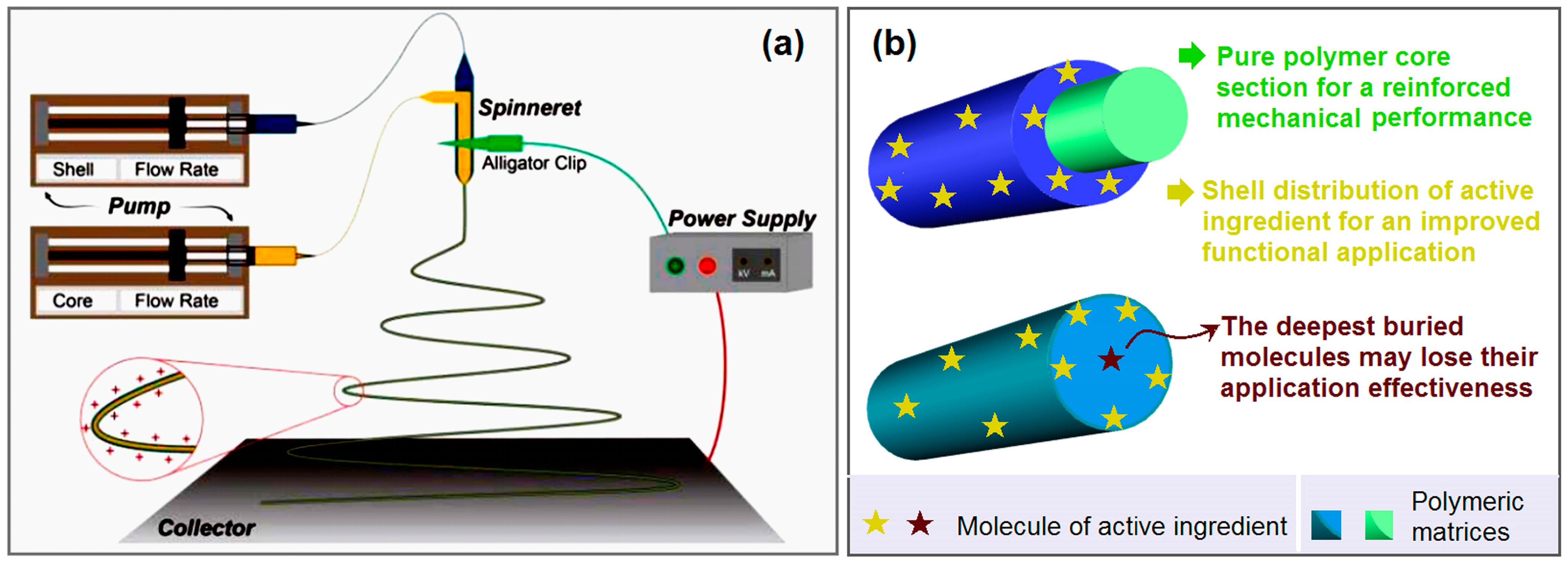
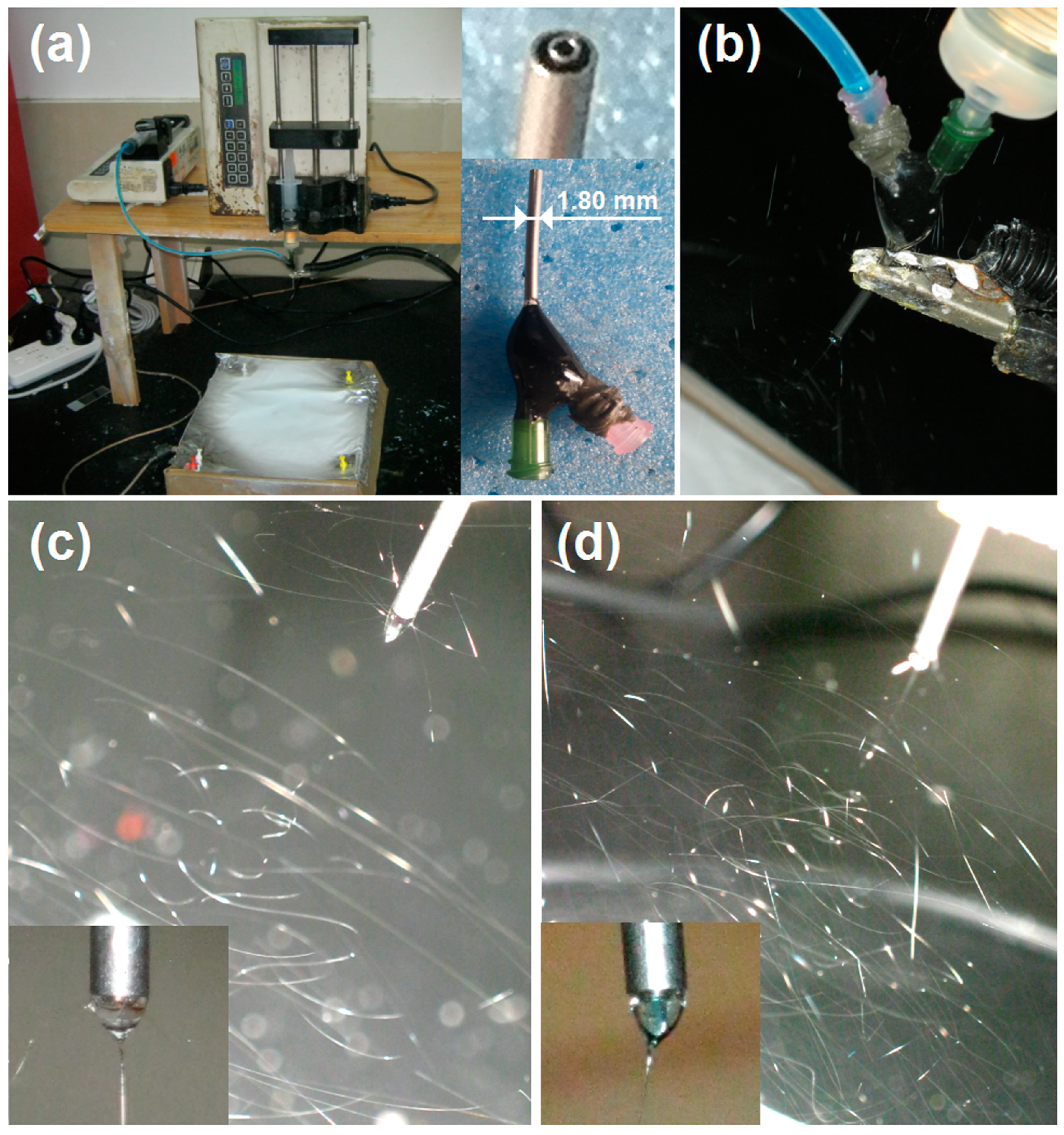
2.1. Implementation of Coaxial Electrospinning

A diagram of the coaxial electrospinning process is shown in Figure 1a. The implementation of coaxial electrospinning is almost the same as single-fluid blending electrospinning. The only difference is that two syringe pumps are simultaneously switched on to drive both the core and shell working fluids to the electrical field through a concentric spinneret. However, the resultant core–shell nanofibers are able to provide a powerful platform for fabricating numerous advanced functional nanomaterials. In this study, the strategy has two key elements (Figure 1b): one is the pure PEO core section for the reinforced mechanical performance, and the other is the shell distribution of VK3 molecules for the antibacterial function, preventing the potential waste of VK3 embedded in the innermost section of monolithic composite nanofibers.
In this study, two electrospinnable working fluids were prepared. Fluid 1 consisted of 5% (w/v) PEO, 4% (w/v) PVA-co-PE, and 0.8% (w/v) VK3 in a solvent mixture of n-propyl alcohol and deionized water with a volume ratio of 7:3. Fluid 2 comprised 5% (w/v) PEO in a mixed solvent of n-propyl alcohol and deionized water with a volume ratio of 7:3. Two types of nanofibers were fabricated. Monolithic nanofibers (F1) were directly prepared from Fluid 1 (i.e., the shell working fluid) using a single-fluid blending electrospinning process. Core–shell nanofibers (F2) were prepared using coaxial electrospinning. The experimental parameters of the operations and the theoretical contents of VK3 within the F1 and F2 nanofibers are included in Table 1.
The declaration that electrospinning is a facile process for producing polymeric nanofibers has two implication. One is that the nanofibers are produced in a single step and a straightforward manner. The other is that the electrospinning system is easy to set up. The whole homemade electrospinning system, which was simply composed of a power supply, two syringe pumps, a spinneret, and a collector, is presented in Figure 2a. The spinneret is the key element [65,66,67]. In this study, a homemade concentric spinneret was utilized, which was composed of a G22 stainless steel capillary (with inner and outer diameters of 0.51 mm and 0.82 mm, respectively) for guiding the core fluid and a G15 stainless steel capillary (with inner and outer diameters of 1.36 mm and 1.80 mm, respectively) for directing the shell fluid. Its outlet and its whole structure are shown in the top-right and bottom-right insets of Figure 2a, respectively. Figure 2b shows a convergent point of a series of elements, including all of the working fluids and an alligator clip for transferring electrostatic energy from the power supply to the working fluids.
The initiation of any electrohydrodynamic atomization (EHDA, including electrospinning, electrospraying, and e-jet printing) requires sufficient electrostatic energy to overcome the surface tension of the liquid pumped out from the outlet of the spinneret [68,69]. If the working fluid is electrospinnable, it is an electrospinning process; otherwise, it is an electrospraying procedure [46,70]. In this study, both Fluid 1 and Fluid 2 had sufficient electrospinnability. Thus, the homogeneous F1 nanofibers could be fabricated robustly and continuously. A typical digital image of the single-fluid electrospinning of the shell solution is given in Figure 2c. The process includes three well-known steps, i.e., the formation of a Taylor cone, a straight fluid jet, and an unstable region with a gradual increase in unstable whipping and bending loops. When the core fluid was simultaneously pumped into the spinneret, the process became a typical coaxial electrospinning process. The shell and core fluids were highly compatible because they were prepared from the same solvent mixture of n-propyl alcohol and deionized water with a volume ratio of 7:3. As anticipated, the coaxial process is smooth and robust, as the digital photos in Figure 2c,d show.

2.2. Morphology and Inner Structure

Figure 3a–d show the SEM images and diameter distributions of the nanofibers. The blended electrospun nanofibers, F1, do not have a very uniform diameter size, with an average of 0.978 ± 0.177 μm, which might have been caused by some unstable moments during the uniaxial electrospinning process. In contrast, coaxial electrospun fibers have a much more uniform diameter distribution, with an average of 1.038 ± 0.094 μm. Compared with F1, F2 has a bigger average diameter, which could be due to the slightly higher total feed rate compared to that used for F1 at the same applied high voltage. Through coaxial electrospinning, F1 was coated on the linear PEO core surface. Thus, this technology can ensure a larger surface area. Moreover, the core–shell structure will generally grant composite fibers a high tensile strength.
The TEM image in Figure 3e shows that the fiber has a distinctive core–shell structure with a 289.8 nm diameter and an approximately 53.5 nm core diameter. This is consistent with the structure of the concentric spinneret. It is also clear that the surface of the nanofiber has numerous shallow sags and crests. The diameter is much smaller than the value obtained from the SEM image. This discrepancy could be caused by the process of sample preparation, which can result in the stretching of the nanofibers and the shrinkage of their diameters. Meanwhile, the core section is very slim, which may be attributable to the above-mentioned sampling and also the fact that the solute in the core fluid was only PEO, with a concentration of 5% (w/v). In contrast, the solutes in the shell fluid included PEO, PVA-co-PE, and VK3 at a higher overall concentration of 9.8% (w/v), almost twice that of PEO in the core fluid.

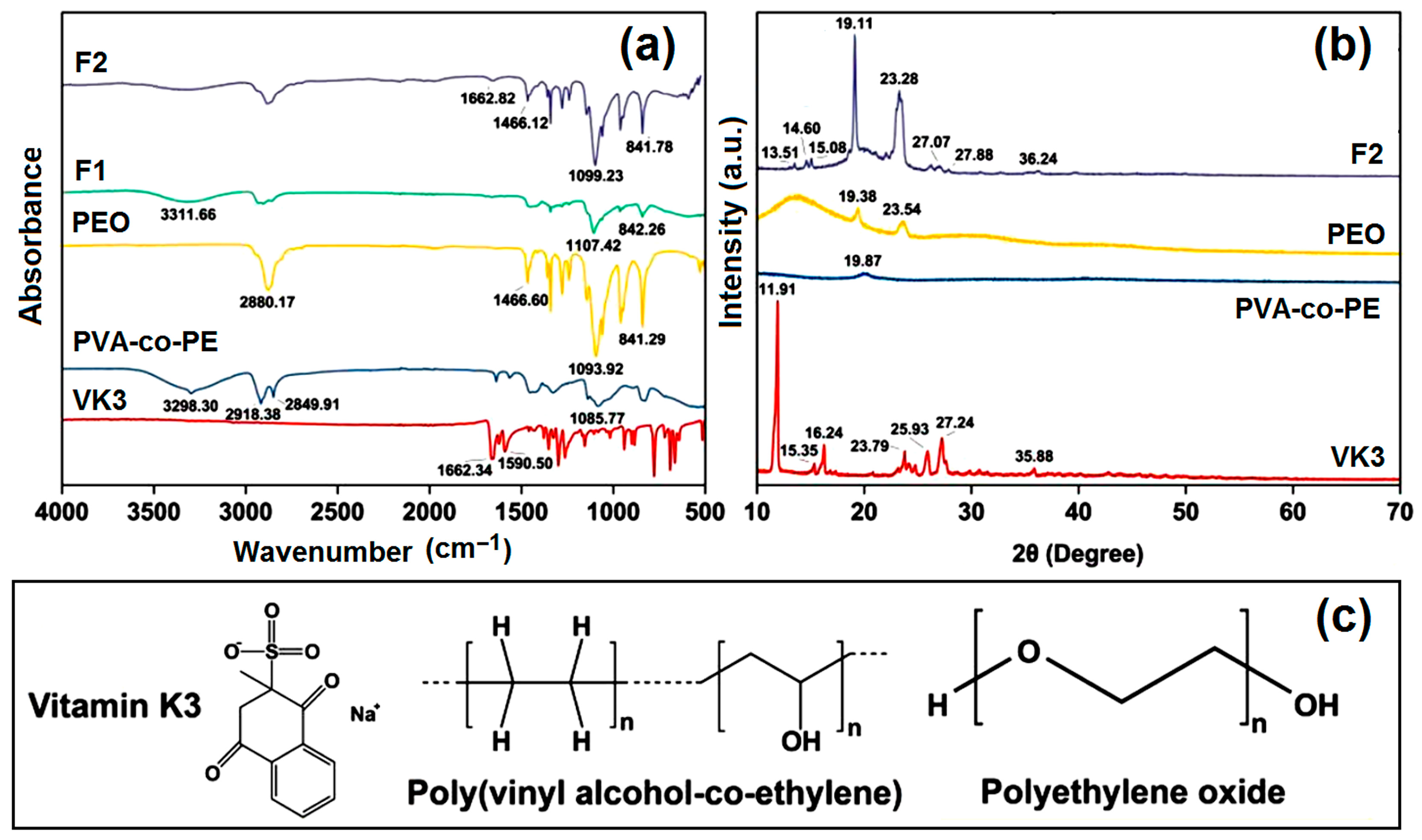
2.3. Physical State and Compatibility

The FTIR spectra, XRD patterns, and molecular formulas of the raw materials are included in Figure 4. Figure 4a shows that the FTIR curve of the PVA-co-PE fiber membrane shows four main absorbance peaks: 3298 cm−1 due to O-H stretching, 2917 cm−1 and 2849 cm−1 due to C-H bending in CH3 and CH2, and 1085 cm−1 due to C-O stretching [71]. In the PEO curve, the peaks at 1093 cm−1 and 841 cm−1 indicate the asymmetric stretching and bending of C-O-C, respectively [72]. The two nanofibers form O-H and C-O-C bonds due to PVA-co-PE and PEO, respectively. As for VK3, the characteristic peak at 1662 cm−1 is attributed to C=O vibration. The C-C stretching vibration of an aromatic group is responsible for the peak at 1590 cm−1, which can be observed in the F1 and F2 curves as well. As indicated by its molecular formula, VK3 has a benzene ring and C=O and S=O groups; thus, it is easy for VK3 molecules to form hydrogen bonds with -OH within the molecules of PVA-co-PE and PEO. Meanwhile, its benzene ring can form large π electron clouds with the long carbon chains of two polymeric matrices.
X-ray diffraction (XRD) patterns present the physical states of components within the polymeric composites [73,74,75,76]. In Figure 4b, the XRD data show that raw VK3 is a typical crystal with some sharp peaks, and PEO has a degree of crystallinity because its XRD pattern has two peaks at 19.38° and 23.54°, which also appear at similar positions in the XRD pattern of the F2 nanofiber. In F2 nanofibers, VK3 can recrystallize during the solidification period. Some small peaks in the F2 XRD pattern can be attributed to VK3, such as 15.08°, 27.07°, 27.88°, and 36.24°. As shown in the SEM image, VK3 was not severely agglomerated. Using the large surface area of electrospun nanofibers, the utilization of VK3 can be drastically improved.

2.4. Mechanical Properties

Reinforcement can be inferred from micro tension tests. Three nanofiber membranes were applied in these tests, and the curves (stress versus strain) are shown in Figure 5. Both prepared non-woven membranes display good toughness and strength. They both have more than 150% strain, and the breaking elongation is 185.800 ± 13.329% for F1 and 194.567 ± 14.027% for F2. The higher elongation of F2 could be caused by the PEO core, which is a high-toughness material. It is clear that the two polymers have slightly different intrinsic mechanical properties. PEO can be used to extend the strain length, but PVA-co-PE is preferable for improving the tensile strength. However, the high content of PVA-co-PE in F1 grants it high tensile strength. F1 has better tensile strength (2.917 ± 0.091 MPa) than F2 (1.850 ± 0.197 MPa). Young’s modulus, which indicates the ability of the reacting material to resist elastic deformation, is lower for F2 (1.050 ± 0.115 MPa) than for F1 (1.643 ± 0.061 MPa), which demonstrates the toughness of F2. Mechanical properties are important performance indicators of PPE materials. Only PPE with high strength and toughness have substantial application value. Specifically, high strength can better protect the wearer, and high toughness can better adapt to the wearer’s various activities, reducing the inconvenience caused by wearing PPE.

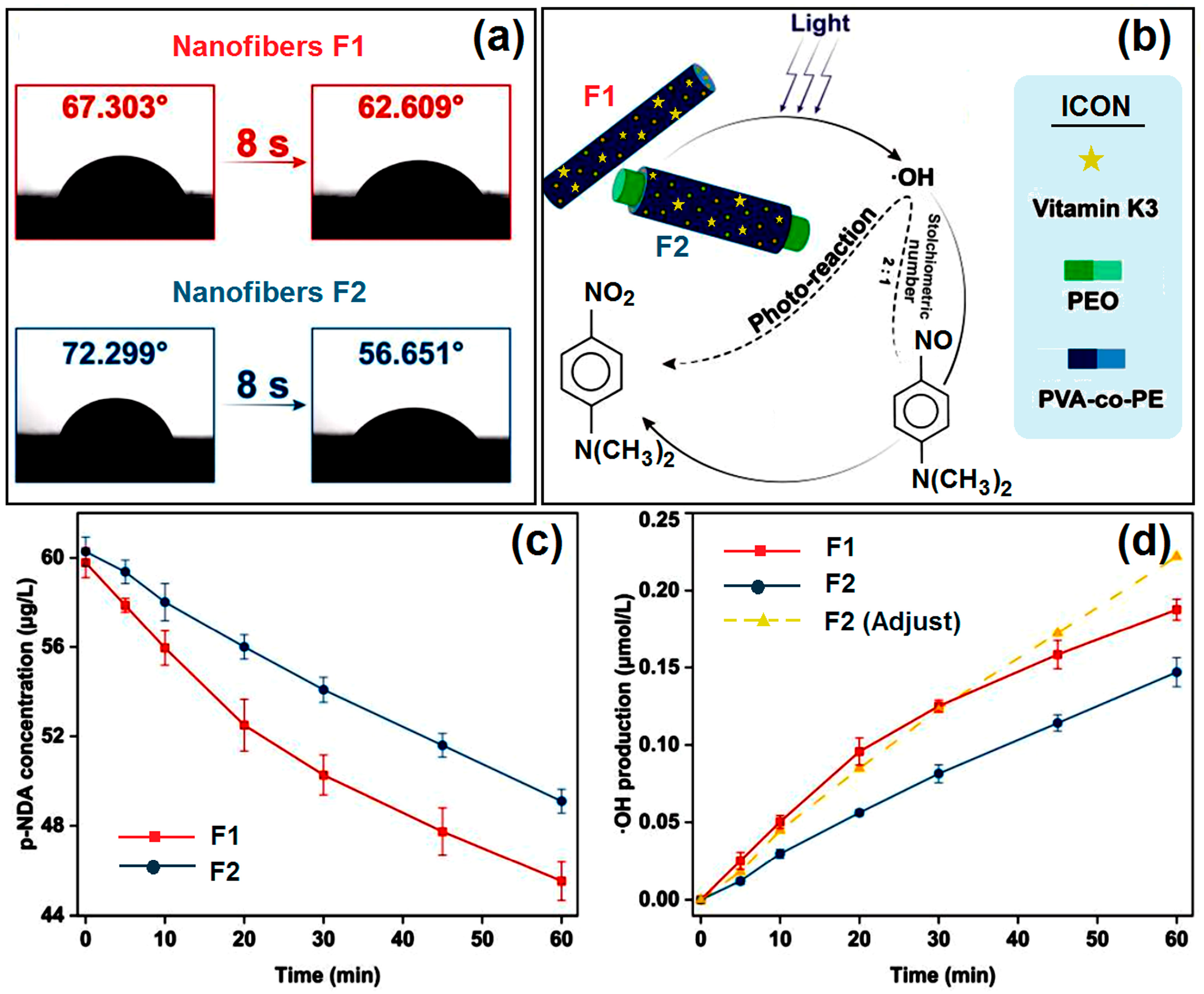
2.5. Water Contact Angle Tests

Hydrophobicity was assessed using water contact angle tests. For this PPE membrane, good hydrophilic performance will promote the production of ROS, which can be generated by VK3 when exposed to an aqueous environment and illumination. Various body fluids can provide a natural aqueous environment for PPE. Thus, the hydrophilic performance of the prepared material will decide how well the environment can be utilized. Because PEO is a hydrophilic material, the prepared F1 and F2 nanofibers have high hydrophilicity. As shown in Figure 6a, they both have low WCAs: 67.303 ± 0.872° (F1) and 72.299 ± 1.922° (F2). Having many hydroxyl groups, on the one hand, can promote the production of ·OH and, on the other hand, can enhance the hydrophilic performance.

2.6. Photoreaction Tests

A photoreaction was conducted to degrade p-NDA, which reacts with ·OH in a certain ratio: two hydroxyl radicals can reduce one p-NDA molecule (shown in Figure 6b). In Figure 6c, it can be easily observed that the concentration of p-NDA continuously decreased under a xenon lamp for 60 min. F1 and F2 degraded 23.857 ± 0.917% and 18.530 ± 1.043% of p-NDA, respectively. According to the stoichiometric relationship between ·OH and p-NDA, we demonstrate the production of ·OH as well. However, in these tests, we used fibrous membranes with the same weight, whereas the mass percentages of VK3 in uniaxial and core–shell fibers were different. Thus, using an adjustment process, we found that ·OH production using F2 reached 0.222 μmol/L in 60 min, which is a little higher than when using F1 (0.188 ± 0.007 μmol/L), as illustrated in Figure 6d.
It can be seen that VK3 dispersed on the shell of the coaxial fiber has a higher utilization rate than VK3 dispersed in the monolithic fiber. As this photoreaction is most likely to occur on the surface of the nanofiber, the core–shell structure will help improve the utilization efficiency of VK3. Using the photoreaction test, the hydroxyl radicals generated with the different structures, F1 and F2, were quantified, which indicated that the nanofibers with the coaxial structure are more suitable for the photoreaction application of VK3 in the drug-loading mode. The generation of free radicals via photoinitiation is an important antibacterial method suitable for daily life. This experiment confirmed that adding photoactive VK3 to nanofibers is a new method that can be applied to PPE.

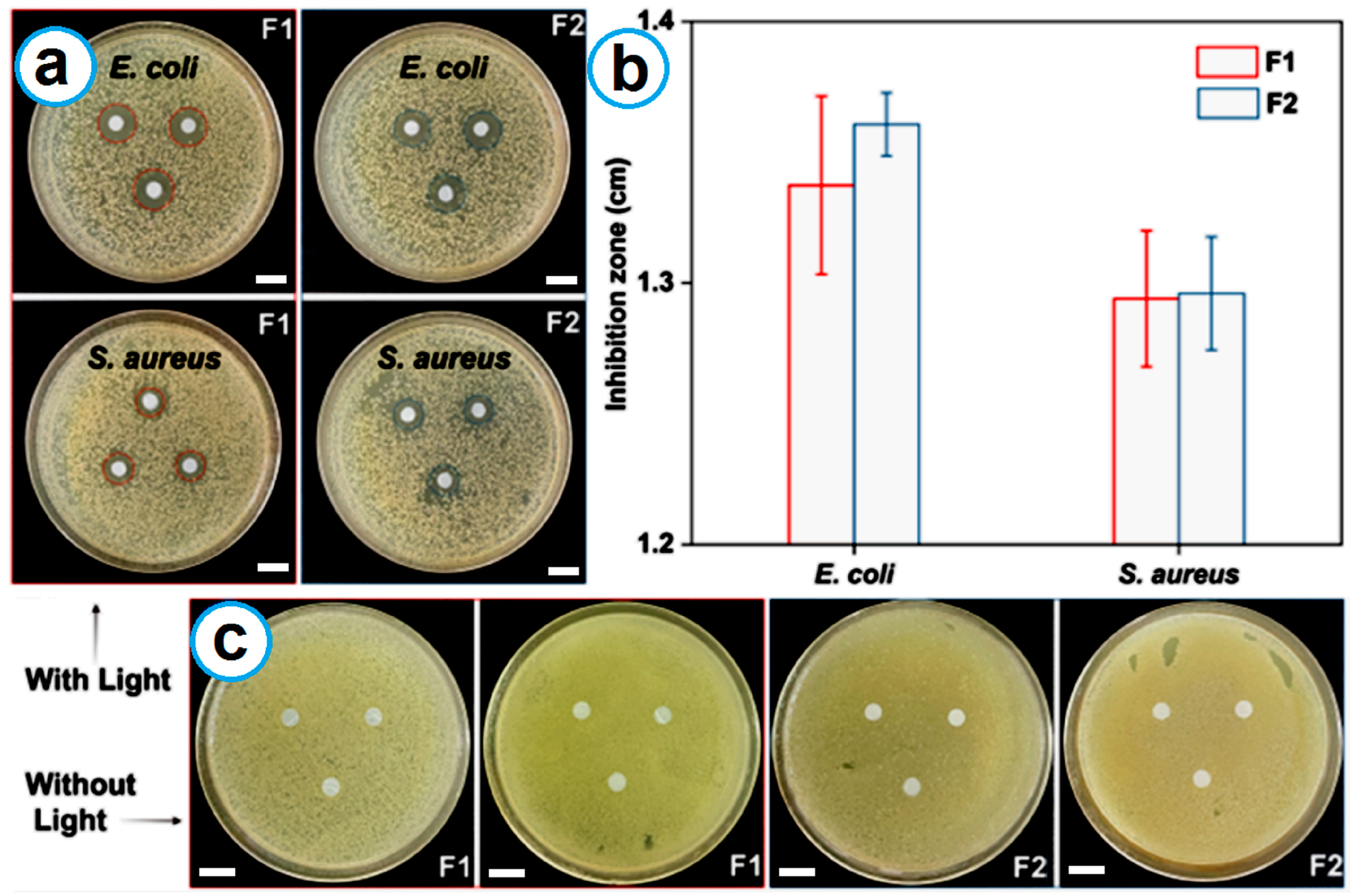
2.7. Antibacterial Tests

The antibacterial performance of the two prepared fibrous membranes under illumination was evaluated in a 37 °C incubator. The experimental results are included in Figure 7a–c. After 24 h of cultivation under light at a constant temperature, both F1 and F2 showed clear inhibition zones in both S. aureus and E. coli, indicating that both materials have good antibacterial activity under light. F1 produced 1.337 ± 0.034 cm and 1.294 ± 0.026 cm inhibition zones for E. coli and S. aureus, respectively. F2 has slightly higher antibacterial performance than F1: 1.361 ± 0.012 cm and 1.296 ± 0.022 cm for E. coli and S. aureus, respectively. Although these data are not statistically significant, the VK3 content in F2 was 5.41% (w/w), whereas that in F1 was 8.16% (w/w). With only 66% of the content in F1, the core–shell F2 nanofibers were still able to generate slightly larger zones, indicating better antibacterial performance. The antibacterial performance can certainly be further improved using two approaches in the future. One approach is to increase the flow rate of the core fluid or decrease the flow rate of the shell fluid to create core–shell nanofibers with a thinner shell section. The other is to adjust the VK3 concentration in the working fluid.
For comparison, without light irradiation, neither sample produced inhibition zones, which further reflects the photoinduced antibacterial activity of VK3. It is precisely because of the existence of VK3 that F1 and F2 can produce ROS such as ·OH. These ROS have the ability to eliminate bacteria. Therefore, the two prepared fibrous membranes have antibacterial activity under sunlight conditions and can function as PPE or a part of PPE. The results reported here suggest that polymers, regardless of whether they have antibacterial effects [77,78,79] or are inert as matrices [68,80,81,82], can be facilely converted using electrospinning into certain forms for a wide variety of functional applications, including PPE.
The development of bioactive materials for specific functional applications involves a series of methods [83,84] and mainly relies on two aspects, i.e., the reasonable selections of raw ingredients and material conversion technologies [85,86,87]. In this nano era, nanotechnologies are frequently introduced into the biomedical and healthcare fields [88,89,90,91]. The popularity of electrospinning and the resultant biomedical nanofibers are fine demonstrations [92,93,94,95]. However, as nanoscience and nanoengineering progress to “small, order, structure, and device”, multiple-fluid electrospinning and the related multi-chamber nanostructures will play an increasingly important role in realizing elaborate material designs for functional applications [34,96,97]. This investigation is just an example of developing advanced bioactive core–shell nanomaterials with an improved functional performance resulting from the shell distribution of the active ingredient and a pure core polymeric matrix. In the literature, numerous nanofiber-based bioactive nanomaterials are reported in which the active ingredients are homogeneously distributed throughout the polymeric matrices. Based on the protocols reported here, all such medical nanofibers can be updated to improve their functional performance simply by concentrating the active ingredient on the surface. In addition, some recent publications have revealed a series of strategies for developing novel PPE [98,99,100], and an effective combination of those strategies and the present core–shell VK3-loaded nanofibers is expected to bring about new types of nano PPE in the future.

3. Materials and Methods

3.1. Materials

Polyethylene oxide (PEO, MW = 300,000) and menadione (also named vitamin K3, VK3, 98%) were purchased from Shanghai Macklin Biochemical Co., Ltd. (Shanghai, China). Poly(vinyl alcohol-co-ethylene) (PVA-co-PE, 32% ethylene) was obtained from Aldrich Chemical Co., Inc. (Shanghai, China). Propanol (AR, 99.5%) and PBS tablets were provided by Sinopharm Chemical Reagent Co., Ltd. (Shanghai, China). N,N-Dimethyl-4-nitrosoaniline (p-NDA, 98%) was obtained from Shanghai Macklin Biochemical Co., Ltd. (Shanghai, China). Other solvents and reagents were analytically pure. Deionized water was used in all preparations.

3.2. Preparing Nanofibers Using Coaxial Electrospinning

For coaxial electrospinning, Table 1 shows the methods used for core and shell solution preparation. In the two electrospinning processes, the collector distance was fixed at 17 cm. The flow rate ratio of core versus shell working fluids was controlled at 1:1 in volume, and the applied voltage was altered to the appropriate value listed in Table 1. On the basis of these parameters, nanofibers can be prepared continuously and stably.
In the homemade coaxial electrospinning apparatus, the two working fluids were driven by two pumps (KDS100, Cole-Parmer, Holliston, MA, USA) into the core and shell of the spinneret, separately. The working fluids gathered at the tip of the spinneret, and under the high-voltage electrostatic field provided by the power supply (ZGF 60 kV/2 mA, Wuhan Hua-Tian Corp., Wuhan, China), a Taylor cone gradually formed. When the electrostatic repulsion overcame the viscosity force within the Taylor cone, the solution was injected, and two stages were noted: a straight jet and whipping and swinging. The working fluid was solidified and then collected using the aluminum foil collector (Figure 2a).

3.3. Characterizations

The morphology and inner structure of the obtained nanofibers were observed by using field emission scanning electron microscopy (SEM, FEI Quanta450FEG, FEI Corporation, Hillsboro, OR, USA) and transmission electron microscopy (TEM, JEM 2200F, JEOL, Tokyo, Japan), respectively. For SEM, samples were observed at 20 kV after they had been gold-sputtered with a 5 nm thick coat using a vacuum turbo evaporator (Q150TES, Quorum, UK). In TEM tests, nanofiber samples were displayed on copper grids and observed at a high voltage (100 kV). The diameters of the fibers in the SEM and TEM images were measured using ImageJ V1.8.0 (National Institutes of Health, Bethesda, MD, USA).
The physical state and chemical compatibility of the nanofibers were determined using X-ray diffraction (XRD, D8 ADVANCE, Bruker, Karlsruhu, Germany) and Fourier transform infrared spectroscopy (FTIR, Spectrum 100, Perkin-Elmer, Billerica, MA, USA). In XRD analysis, samples were analyzed at a voltage of 40 kV and a current of 40 mA. Data were collected over a 2θ range from 10° to 70° at 5° per minute. In FTIR tests, data were collected in the range from 4000 to 450 cm−1 at a resolution of 2 cm−1, and each sample was scanned eight times.
The water contact angles (WCAs) of different samples were determined with an instrument to measure interfacial tension (JC2000C1, Shanghai Zhongchen Digital Technology Apparatus Co., Ltd., Shanghai, China). For this measurement, deionized water was used as the test liquid. Samples with a 5 cm length and a 2 cm width were used for water contact angle testing. One droplet of water was dropped on the sample, and the wetting process was recorded using a built-in high-speed camera. The corresponding results were measured using ImageJ with six repetitions and recorded as mean ± S.D.
Micro-tensile tests were implemented using rectangular samples from different prepared nanofiber membranes. The geometrical parameters of the different samples were kept at 50 mm in length and 20 mm in width. Their thickness was measured with a micrometer caliper, and the thickness values were 0.107 mm for F1 and 0.104 mm for F2. A micro-tensile testing machine (ZwickRoell GmbH & Co. KG, Ulm, Germany) was used in this test, and the distance between clamps was fixed at 20 mm. The model selected was fiberboard.
Photoreaction tests were carried out using different nanofiber membranes. A 50-milligram membrane was immersed in 50 mL of 50 μM p-NDA and put under a xenon lamp to be irradiated for different times (0, 5, 10, 20, 30, 45, and 60 min). The distance between the modulator tube and the samples was fixed at 15 cm. The absorbance of the samples was tested using a UV–vis spectrometer (UV-2102PC, Unico Instrument Co., Ltd., Shanghai, China) at 440 nm. The standard curve of p-NDA was plotted in advance, and the linear equation is A = 0.00469 + 0.02763 × C with R2 = 0.99958. The amount of ·OH was calculated from the relationship between p-NDA and ·OH as reactants [101], as shown in Figure 8. Experiments were repeated three times, and the results were recorded as mean ± S.D.
The Kirby–Bauer disc diffusion method was used to evaluate the antibacterial performance of different samples. Staphylococcus aureus (S. aureus) and Escherichia coli (E. coli) were used to conduct these experiments. First, 300 μL of each bacterial solution (105 CFU/mL) was uniformly coated on a 10 cm Luria–Bertani nutrient agar plate. The nanofiber membrane samples were prepared as 6 mm circular plates and sterilized using ultraviolet irradiation for 30 min. Three samples from each group were placed on LB culture plates. The plates were put into an incubator for 24 h at 37 °C and exposed to light. All operations were performed in a sterile environment. After that, the inhibition zones were measured and recorded as mean ± S.D.

3.4. Statistical Analysis

The data are expressed as the mean ± standard deviation (S.D.). The statistical analysis of the data was performed using the analysis of variance (ANOVA). ANOVA was followed by the Dunnett test whenever necessary (Origin 8.1, Origin Lab, Northampton, MA, USA), and a value of p < 0.05 was considered statistically significant.

4. Conclusions

In this work, a blend of electrospinning and coaxial electrospinning was successfully implemented, and uniaxial fibers and core–shell fibers were prepared using different processes. SEM and TEM images indicated that the core–shell fibers had a more uniform size distribution and a clear core–shell inner structure. XRD and FTIR showed that the components had sufficient compatibility and that VK3 could be uniformly dispersed in monolithic fibers (F1) and the shell sections of core–shell nanofibers (F2). The two prepared fibrous membranes were both hydrophilic materials with acceptable mechanical performance. The photoreaction experiments showed that they both had the desired performance in degrading p-NDA. Compared with the monolithic F1 nanofibers from the single-fluid blending electrospinning, on one hand, the core–shell F2 nanofibers could ensure better mechanical performance through the pure core section. On the other hand, distributing VK3 only on the shell in F2 is conducive to a higher utilization rate of the loaded VK3 molecules. Of course, the core–shell nanofibers are more complex to fabricate, particularly on a large scale. Overcoming this challenge and exploring the many potential interesting applications of electrospun core–shell nanofibers are major objectives for their industrial production.

Author Contributions

Conceptualization, W.G., M.-L.W. and D.-G.Y.; methodology, W.G., M.-L.W., D.-G.Y. and S.W.A.B.; investigation, W.G., M.-L.W. and Y.L.; writing—original draft preparation, W.G. and D.-G.Y.; writing—review and editing, Y.L., D.-G.Y. and S.W.A.B.; visualization, Y.L., W.G. and M.-L.W.; supervision, D.-G.Y.; project administration, D.-G.Y.; funding acquisition, D.-G.Y. and S.W.A.B. All authors have read and agreed to the published version of the manuscript.

Funding

This research and the APC was funded by the Institutional Strategic Grant of Saint Francis University (grant number ISG190101) and the Shanghai Industrial Collaboration Project (grant numbers HCXBCY-2023-042 and XTCX-KJ-2023-44).

Institutional Review Board Statement

Not applicable.

Informed Consent Statement

Not applicable.

Data Availability Statement

The data supporting the findings in this manuscript are available from the corresponding authors upon reasonable.

Acknowledgments

Yuexin Ji is highly appreciated for her help in this research work.

Conflicts of Interest

The authors declare no conflicts of interest.

References

  1. Dolez, P.I.; Marsha, S.; McQueen, R.H. Fibers and Textiles for Personal Protective Equipment: Review of Recent Progress and Perspectives on Future Developments. Textiles 2022, 2, 349–381. [Google Scholar] [CrossRef]
  2. Karim, N.; Afroj, S.; Lloyd, K.; Oaten, L.C.; Andreeva, D.V.; Carr, C.; Farmery, A.D.; Kim, I.-D.; Novoselov, K.S. Sustainable Personal Protective Clothing for Healthcare Applications: A Review. ACS Nano 2020, 14, 12313–12340. [Google Scholar] [CrossRef]
  3. Agarwal, R. The Personal Protective Equipment Fabricated via 3D Printing Technology During COVID-19. Ann. 3D Print. Med. 2022, 5, 100042. [Google Scholar] [CrossRef] [PubMed]
  4. Han, C.; Han, X.; Han, J.; He, M.; Peng, S.; Zhang, C.; Liu, X.; Gou, J.; Wang, J. Light-Stimulated Synaptic Transistor with High PPF Feature for Artificial Visual Perception System Application. Adv. Funct. Mater. 2022, 32, 2113053. [Google Scholar] [CrossRef]
  5. Shi, J.; Li, H.; Xu, F.; Tao, X. Materials in Advanced Design of Personal Protective Equipment: A Review. Mater. Today Adv. 2021, 12, 100171. [Google Scholar] [CrossRef]
  6. Cook, T.M. Personal Protective Equipment During the Coronavirus Disease (COVID) 2019 Pandemic—A Narrative Review. Anaesthesia 2020, 75, 920–927. [Google Scholar] [CrossRef]
  7. Su, X.; Jia, C.; Xiang, H.; Zhu, M. Research Progress in Preparation, Properties, and Applications of Medical Protective Fiber Materials. Appl. Mater. Today 2023, 32, 101792. [Google Scholar] [CrossRef]
  8. Hirschmann, M.T.; Hart, A.; Henckel, J.; Sadoghi, P.; Seil, R.; Mouton, C. COVID-19 Coronavirus: Recommended Personal Protective Equipment for the Orthopaedic and Trauma Surgeon. Knee Surg. Sports Traumatol. Arthrosc. 2020, 28, 1690–1698. [Google Scholar] [CrossRef] [PubMed]
  9. Zeng, Y.; Wang, L.; Zhang, L.; Yu, J.Q. An Acid Resistant Nanofiltration Membrane Prepared From a Precursor of Poly(S-Triazine-Amine) by Interfacial Polymerization. J. Membr. Sci. 2018, 546, 225–233. [Google Scholar] [CrossRef]
  10. Weng, R.; Huang, X.; Liao, D.; Xu, S.; Peng, L.; Liu, X. A Novel Cellulose/Chitosan Composite Nanofiltration Membrane Prepared with Piperazine and Trimesoyl Chloride by Interfacial Polymerization. RSC Adv. 2020, 10, 1309–1318. [Google Scholar] [CrossRef]
  11. Tran, N.T.; Kim, J.; Othman, M.R. Microporous ZIF-8 Membrane Prepared from Secondary Growth for Improved Propylene Permeance and Selectivity. Microporous Mesoporous Mater. 2019, 285, 178–184. [Google Scholar] [CrossRef]
  12. Kidambi, P.R.; Mariappan, D.D.; Dee, N.T.; Vyatskikh, A.; Zhang, S.; Karnik, R.; Hart, A.J. A Scalable Route to Nanoporous Large-Area Atomically Thin Graphene Membranes by Roll-to-Roll Chemical Vapor Deposition and Polymer Support Casting. ACS Appl. Mater. Interfaces 2018, 10, 10369–10378. [Google Scholar] [CrossRef] [PubMed]
  13. Liu, A.; Kovacik, P.; Peard, N.; Tian, W.; Goktas, H.; Lau, J.; Dunn, B.; Gleason, K.K. Monolithic Flexible Supercapacitors Integrated into Single Sheets of Paper and Membrane via Vapor Printing. Adv. Mater. 2017, 29, 1606091. [Google Scholar] [CrossRef]
  14. Oh, H.J.; McGrath, J.E.; Paul, D.R. Water and Salt Transport Properties of Disulfonated Poly(Arylene Ether Sulfone) Desalination Membranes Formed by Solvent-Free Melt Extrusion. J. Membr. Sci. 2018, 546, 234–245. [Google Scholar] [CrossRef]
  15. Xu, D.; Zheng, X.; Xiao, R. Hydrophilic Nanofibrous Composite Membrane Prepared by Melt-Blending Extrusion for Effective Separation of Oil/Water Emulsion. RSC Adv. 2017, 7, 7108–7115. [Google Scholar] [CrossRef]
  16. Sun, Y.; Zhou, J.; Zhang, Z.; Yu, D.-G.; Bligh, S.W.A. Integrated Janus Nanofibers Enabled by a Co-Shell Solvent for Enhancing Icariin Delivery Efficiency. Int. J. Pharm. 2024, 658, 124180. [Google Scholar] [CrossRef]
  17. Gong, W.; Yang, W.; Zhou, J.; Zhang, S.; Yu, D.-G.; Liu, P. Engineered Beads-on-a-String Nanocomposites for an Improved Drug Fast-Sustained Bi-Stage Release. Nanocomposites 2024, 10, 240–253. [Google Scholar] [CrossRef]
  18. Mao, H.; Zhou, J.; Yan, L.; Zhang, S.; Yu, D.-G. Hybrid Films Loaded with 5-Fluorouracil and Reglan for Synergistic Treatment of Colon Cancer via Asynchronous Dual-Drug Delivery. Front. Bioeng. Biotechnol. 2024, 12, 1398730. [Google Scholar] [CrossRef] [PubMed]
  19. Chen, S.; Zhou, J.; Fang, B.; Ying, Y.; Yu, D.-G.; He, H. Three EHDA Processes from a Detachable Spinneret for Fabricating Drug Fast Dissolution Composites. Macromol. Mater. Eng. 2024, 309, 2300361. [Google Scholar] [CrossRef]
  20. Ji, Y.; Zhao, H.; Liu, H.; Zhao, P.; Yu, D.-G. Electrosprayed Stearic-Acid-Coated Ethylcellulose Microparticles for an Improved Sustained Release of Anticancer Drug. Gels 2023, 9, 700. [Google Scholar] [CrossRef]
  21. Chen, X.; Yan, S.; Wen, S.; Chen, J.; Xu, J.; Wang, C.; Lu, X. Chelating Adsorption-Engaged Synthesis of Ultrafine Iridium Nanoparticles Anchored on N-Doped Carbon Nanofibers Toward Highly Efficient Hydrogen Evolution in Both Alkaline and Acidic Media. J. Colloid Interface Sci. 2023, 641, 782–790. [Google Scholar] [CrossRef] [PubMed]
  22. Li, D.; Yue, G.; Li, S.; Liu, J.; Li, H.; Gao, Y.; Liu, J.; Hou, L.; Liu, X.; Cui, Z.; et al. Fabrication and Applications of Multi-Fluidic Electrospinning Multi-Structure Hollow and Core–Shell Nanofibers. Engineering 2022, 13, 116–127. [Google Scholar] [CrossRef]
  23. Wang, X.; Feng, C. Chiral Fiber Supramolecular Hydrogels for Tissue Engineering. WIREs Nanomed. Nanobiotechnol. 2023, 15, e1847. [Google Scholar] [CrossRef]
  24. Lu, H.; Zhao, Y.; Qin, S.; Zhang, Y.; Liu, J.; Zhang, J.; Feng, C.; Zhao, W. Fluorine Substitution Tunes the Nanofiber Chirality of SupraMolecular Hydrogels to Promote Cell Adhesion and Proliferation. Adv. Fiber Mater. 2023, 5, 377–387. [Google Scholar] [CrossRef]
  25. de Farias, B.S.; Rizzi, F.Z.; Ribeiro, E.S.; Diaz, P.S.; Sant’Anna Cadaval Junior, T.R.; Dotto, G.L.; Khan, M.R.; Manoharadas, S.; de Almeida Pinto, L.A.; dos Reis, G.S. Influence of Gelatin Type on Physicochemical Properties of Electrospun Nanofibers. Sci. Rep. 2023, 13, 15195. [Google Scholar] [CrossRef] [PubMed]
  26. Kang, S.; Hou, S.; Chen, X.; Yu, D.-G.; Wang, L.; Li, X.; Williams, G.R. Energy-Saving Electrospinning with a Concentric Teflon-Core Rod Spinneret to Create Medicated Nanofibers. Polymers 2020, 12, 2421. [Google Scholar] [CrossRef] [PubMed]
  27. Sun, L.; Zhou, J.; Chen, Y.; Yu, D.-G.; Liu, P. A Combined Electrohydrodynamic Atomization Method for Preparing Nanofiber/Microparticle Hybrid Medicines. Front. Bioeng. Biotechnol. 2023, 11, 1308004. [Google Scholar] [CrossRef]
  28. Qian, C.; Liu, Y.; Chen, S.; Zhang, C.; Chen, X.; Liu, Y.; Liu, P. Electrospun Core–Sheath PCL Nanofibers Loaded with nHA and SimvasTatin and their Potential Bone Regeneration Applications. Front. Bioeng. Biotechnol. 2023, 11, 1205252. [Google Scholar] [CrossRef]
  29. Zhang, Y.; Lu, Y.; Li, Y.; Xu, Y.; Song, W. Poly(Glutamic Acid)-Engineered Nanoplatforms for Enhanced Cancer Phototherapy. Curr. Drug Delivery 2024, 21, 326–338. [Google Scholar] [CrossRef]
  30. Zhou, J.; Yi, T.; Zhang, Z.; Yu, D.-G.; Liu, P.; Wang, L.; Zhu, Y. Electrospun Janus Core (Ethyl Cellulose//Polyethylene Oxide) @ Shell (Hydroxypropyl Methyl Cellulose Acetate Succinate) Hybrids for an Enhanced Colon-Targeted Prolonged Drug Absorbance. Adv. Compos. Hybrid Mater. 2023, 6, 189. [Google Scholar] [CrossRef]
  31. Xu, L.; Li, Q.; Wang, H.; Liu, H.; Yu, D.-G.; Bligh, S.-W.A.; Lu, X. Electrospun Multi-Functional Medicated Tri-Section Janus Nanofibers for an Improved Anti-Adhesion Tendon Repair. Chem. Eng. J. 2024, 492, 152359. [Google Scholar] [CrossRef]
  32. Lv, H.; Liu, Y.; Zhou, J.; Bai, Y.; Shi, H.; Yue, B.; Shen, S.; Yu, D.-G. Efficient Piezophotocatalysis of ZnO@PVDF Coaxial Nanofibers Modified with BiVO4 and Ag for the Simultaneous Generation of H2O2 and Removal of Pefloxacin and Cr(VI) in Water. Chem. Eng. J. 2024, 484, 149514. [Google Scholar] [CrossRef]
  33. Zhang, Z.; Liu, H.; Yu, D.-G.; Bligh, S.-W.A. Alginate-Based Electrospun Nanofibers and the Enabled Drug Controlled Release Profiles: A Review. Biomolecules 2024, 14, 789. [Google Scholar] [CrossRef]
  34. Yu, D.-G.; Gong, W.; Zhou, J.; Liu, Y.; Zhu, Y.; Lu, X. Engineered Shapes Using Electrohydrodynamic Atomization for an Improved Drug Delivery. WIREs Nanomed. Nanobiotechnol. 2024, 16, e1964. [Google Scholar] [CrossRef] [PubMed]
  35. Zhang, Z.; Wisuthiphaet, N.; Nitin, N.; Wang, L.; Kawakita, R.; Jeoh, T.; Sun, G. Photoactive Water-Soluble Vitamin K: A Novel Amphiphilic Photoinduced Antibacterial Agent. ACS Sustain. Chem. Eng. 2021, 9, 8280–8294. [Google Scholar] [CrossRef]
  36. Yang, L.; Zhang, Y.; Hu, X.; Shiu, B.-C.; Lou, C.-W.; Lin, J.-H.; Li, T.-T. Photodynamic Rechargeable Nanofibrous Membranes with High-Efficient Antibacterial/Antiviral Properties for Medical Protection. J. Ind. Eng. Chem. 2023, 120, 410–420. [Google Scholar] [CrossRef]
  37. Zhao, Y.; Liu, Y.; Tian, C.; Liu, Z.; Wu, K.; Zhang, C.; Han, X. Construction of Antibacterial Photothermal PCL/AgNPs/BP Nanofibers for Infected Wound Healing. Mater. Des. 2023, 226, 111670. [Google Scholar] [CrossRef]
  38. Dong, M.; Sun, X.; Bu, T.; Zhang, H.; Wang, J.; He, K.; Li, L.; Li, Z.; Wang, L. 3D/2D TMSs/TiO2 Nanofibers Heterojunctions for Photodynamic-Photothermal and Oxidase-Like Synergistic Antibacterial Therapy Co-Driven by VIS and NIR Biowindows. Compos. Part B 2022, 230, 109498. [Google Scholar] [CrossRef]
  39. Zhang, S.; Chen, H.; Ma, H.; Yu, J.; Liu, L.; Fan, Y. A MoS2QDs/Chitin Nanofiber Composite for Improved Antibacterial and Food Packaging. Int. J. Biol. Macromol. 2022, 209, 737–746. [Google Scholar] [CrossRef] [PubMed]
  40. Ci, H.; Ma, L.; Liu, X.; Liang, Y.; Zheng, Y.; Li, Z.; Zhu, S.; Cui, Z.; Wu, S. Photo-Excited Antibacterial Poly(ε-Caprolactone)@MoS2/ZnS Hybrid Nanofibers. Chem. Eng. J. 2022, 434, 134764. [Google Scholar] [CrossRef]
  41. Belete, T.M. Novel Targets to Develop New Antibacterial Agents and Novel Alternatives to Antibacterial Agents. Hum. Microbiome J. 2019, 11, 100052. [Google Scholar] [CrossRef]
  42. Tang, S.; Ruan, Z.; Ma, A.; Wang, D.; Kou, J. Effect of Vitamin K on Wound Healing: A Systematic Review and Meta-Analysis Based on Preclinical Studies. Front. Pharmacol. 2022, 13, 1063349. [Google Scholar] [CrossRef] [PubMed]
  43. Tintino, S.R.; Oliveira-Tintino, C.D.M.; Campina, F.F.; Weslley Limaverde, P.; Pereira, P.S.; Siqueira-Junior, J.P.; Coutinho, H.D.M.; Quintans-Júnior, L.J.; da Silva, T.G.; Leal-Balbino, T.C.; et al. Vitamin K Enhances the Effect of Antibiotics Inhibiting the Efflux Pumps of Staphylococcus Aureus Strains. Med. Chem. Res. 2018, 27, 261–267. [Google Scholar] [CrossRef]
  44. Yıldırım, H.; Yıldız, M.; Bayrak, N.; Mataracı-Kara, E.; Radwan, M.O.; Jannuzzi, A.T.; Otsuka, M.; Fujita, M.; TuYuN, A.F. Promising Antibacterial and Antifungal Agents Based on Thiolated Vitamin K3 Analogs: Synthesis, Bioevaluation, Molecular Docking. Pharmaceuticals 2022, 15, 586. [Google Scholar] [CrossRef] [PubMed]
  45. Chadar, D.; Camilles, M.; Patil, R.; Khan, A.; Weyhermüller, T.; Salunke-Gawali, S. Synthesis and Characterization of n-Alkylamino Derivatives of Vitamin K3: Molecular Structure of 2-Propylamino-3-Methyl-1,4-Naphthoquinone and Antibacterial Activities. J. Mol. Struct. 2015, 1086, 179–189. [Google Scholar] [CrossRef]
  46. Zhou, J.; Chen, Y.; Liu, Y.; Huang, T.; Xing, J.; Ge, R.; Yu, D.-G. Electrospun Medicated Gelatin/Polycaprolactone Janus Fibers for Photothermal-Chem Combined Therapy of Liver Cancer. Int. J. Biol. Macromol. 2024, 269, 132113. [Google Scholar] [CrossRef]
  47. Chen, X.; Liu, Y.; Liu, P. Electrospun Core–Sheath Nanofibers with a Cellulose Acetate Coating for the Synergistic Release of Zinc Ion and Drugs. Mol. Pharm. 2024, 21, 173–182. [Google Scholar] [CrossRef]
  48. Zhao, P.; Zhou, K.; Xia, Y.; Qian, C.; Yu, D.-G.; Xie, Y.; Liao, Y. Electrospun Trilayer Eccentric Janus Nanofibers for a Combined Treatment of Periodontitis. Adv. Fiber Mater. 2024, 6, 1053–1073. [Google Scholar] [CrossRef]
  49. Wang, M.; Hou, J.; Yu, D.-G.; Li, S.; Zhu, J.; Chen, Z. Electrospun Tri-Layer Nanodepots for Sustained Release of Acyclovir. J. Alloys Compd. 2020, 846, 156471. [Google Scholar] [CrossRef]
  50. Liu, Y.; Chen, X.; Lin, X.; Yan, J.; Yu, D.-G.; Liu, P.; Yang, H. Electrospun Multi-Chamber Core–Shell Nanofibers and Their Controlled Release Behaviors: A Review. WIREs Nanomed. Nanobiotechnol. 2024, 16, e1954. [Google Scholar] [CrossRef]
  51. Cai, M.; He, H.; Zhang, X.; Yan, X.; Li, J.; Chen, F.; Yuan, D.; Ning, X. Efficient Synthesis of PVDF/PI Side-by-Side Bicomponent Nanofiber Membrane with Enhanced Mechanical Strength and Good Thermal Stability. Nanomaterials 2019, 9, 39. [Google Scholar] [CrossRef] [PubMed]
  52. Cai, M.; Zhu, J.; Yang, C.; Gao, R.; Shi, C.; Zhao, J. A Parallel Bicomponent TPU/PI Membrane with Mechanical Strength Enhanced Isotropic Interfaces used as Polymer Electrolyte for Lithium-Ion Battery. Polymers 2019, 11, 185. [Google Scholar] [CrossRef]
  53. Liu, W.; Zhong, T.; Liu, T.; Zhang, J.; Liu, H. Preparation and Characterization of Electrospun Conductive Janus Nanofibers with Polyaniline. ACS Appl. Polym. Mater. 2020, 2, 2819–2829. [Google Scholar] [CrossRef]
  54. Liu, Q.; Xia, M.; Chen, J.; Tao, Y.; Wang, Y.; Liu, K.; Li, M.; Wang, W.; Wang, D. High Performance Hybrid Al2O3/Poly(Vinyl Alcohol-Co-Ethylene) Nanofibrous Membrane for Lithium-ion Battery Separator. Electrochim. Acta 2015, 176, 949–955. [Google Scholar] [CrossRef]
  55. Luzi, F.; Puglia, D.; Dominici, F.; Fortunati, E.; Giovanale, G.; Balestra, G.M.; Torre, L. Effect of Gallic Acid and Umbelliferone on Thermal, Mechanical, Antioxidant and Antimicrobial Properties of Poly (Vinyl Alcohol-Co-Ethylene) Films. Polym. Degrad. Stab. 2018, 152, 162–176. [Google Scholar] [CrossRef]
  56. Huang, K.; Yang, X.; Ma, Y.; Sun, G.; Nitin, N. Incorporation of Antimicrobial Bio-Based Carriers onto Poly(Vinyl Alcohol-Co-Ethylene) Surface for Enhanced Antimicrobial Activity. ACS Appl. Mater. Interfaces 2021, 13, 36275–36285. [Google Scholar] [CrossRef]
  57. Jayeoye, T.J.; Nwabor, O.F.; Rujiralai, T. Synthesis of Highly Stable and Dispersed Silver Nanoparticles/Poly(Vinyl Alcohol-Co-Ethylene Glycol)/Poly(3-Aminophenyl Boronic Acid) Nanocomposite: Characterization and Antibacterial, Hemolytic and Cytotoxicity Studies. J. Ind. Eng. Chem. 2020, 89, 288–300. [Google Scholar] [CrossRef]
  58. Ni, Y.; Yan, K.; Xu, F.; Zhong, W.; Zhao, Q.; Liu, K.; Yan, K.; Wang, D. Synergistic Effect on TiO2 Doped Poly (Vinyl Alcohol-Co-Ethylene) Nanofibrous Film for Filtration and Photocatalytic Degradation of Methylene Blue. Compos. Commun. 2019, 12, 112–116. [Google Scholar] [CrossRef]
  59. Yi, Z.; Cheng, P.; Chen, J.; Liu, K.; Liu, Q.; Li, M.; Zhong, W.; Wang, W.; Lu, Z.; Wang, D. PVA-Co-PE Nanofibrous Filter Media with Tailored Three-Dimensional Structure for High Performance and Safe Aerosol Filtration via Suspension-Drying Procedure. Ind. Eng. Chem. Res. 2018, 57, 9269–9280. [Google Scholar] [CrossRef]
  60. Liang, M.; Wang, F.; Liu, M.; Yu, J.; Si, Y.; Ding, B. N-Halamine Functionalized Electrospun Poly(Vinyl Alcohol-Co-Ethylene) Nanofibrous Membranes with Rechargeable Antibacterial Activity for Bioprotective Applications. Adv. Fiber Mater. 2019, 1, 126–136. [Google Scholar] [CrossRef]
  61. Zhang, Z.; El-Moghazy, A.Y.; Wisuthiphaet, N.; Nitin, N.; Castillo, D.; Murphy, B.G.; Sun, G. Daylight-Induced Antibacterial and Antiviral Nanofibrous Membranes Containing Vitamin K Derivatives for Personal Protective Equipment. ACS Appl. Mater. Interfaces 2020, 12, 49416–49430. [Google Scholar] [CrossRef]
  62. Kandhasamy, S.; Liang, B.; Yang, D.-P.; Zeng, Y. Antibacterial Vitamin K3 Carnosine Peptide-Laden Silk Fibroin Electrospun Fibers for Improvement of Skin Wound Healing in Diabetic Rats. ACS Appl. Bio Mater. 2021, 4, 4769–4788. [Google Scholar] [CrossRef] [PubMed]
  63. Sheng, L.; Zhang, Z.; Sun, G.; Wang, L. Light-Driven Antimicrobial Activities of Vitamin K3 Against Listeria Monocytogenes, Escherichia Coli O157:H7 and Salmonella Enteritidis. Food Control 2020, 114, 107235. [Google Scholar] [CrossRef]
  64. Negri, L.B.; Mannaa, Y.; Korupolu, S.; Farinelli, W.A.; Anderson, R.R.; Gelfand, J.A. Vitamin K3 (Menadione) is a Multifunctional Microbicide Acting as a Photosensitizer and Synergizing with Blue Light to Kill Drug-Resistant Bacteria in Biofilms. J. Photochem. Photobiol. B 2023, 244, 112720. [Google Scholar] [CrossRef]
  65. Shariatzadeh, F.J.; Currie, S.; Logsetty, S.; Spiwak, R.; Liu, S. Enhancing Wound Healing and Minimizing Scarring: A Comprehensive Review of Nanofiber Technology in Wound Dressings. Prog. Mater. Sci. 2024, 147, 101350. [Google Scholar] [CrossRef]
  66. Yan, S.; Qian, Y.; Haghayegh, M.; Xia, Y.; Yang, S.; Cao, R.; Zhu, M. Electrospun Organic/Inorganic Hybrid Nanofibers for Accelerating Wound Healing: A Review. J. Mater. Chem. B 2024, 12, 3171–3190. [Google Scholar] [CrossRef]
  67. Ajalli, N.; Pourmadadi, M.; Yazdian, F.; Abdouss, M.; Rashedi, H.; Rahdar, A. PVA Based Nanofiber Containing GO Modified with Cu Nanoparticles and Loaded Curcumin; High Antibacterial Activity with Acceleration Wound Healing. Curr. Drug Delivery 2023, 20, 1569–1583. [Google Scholar] [CrossRef] [PubMed]
  68. Zhang, S.; Yang, W.; Gong, W.; Lu, Y.; Yu, D.-G.; Liu, P. Recent Progress of Electrospun Nanofibers as Burning Dressings. RSC Adv. 2024, 14, 14374–14391. [Google Scholar] [CrossRef]
  69. Zhang, X.; Yu, N.; Ren, Q.; Niu, S.; Zhu, L.; Hong, L.; Cui, K.; Wang, X.; Jiang, W.; Wen, M.; et al. Janus Nanofiber Membranes with Photothermal-Enhanced Biofluid Drainage and Sterilization for Diabetic Wounds. Adv. Funct. Mater. 2024, 34, 2315020. [Google Scholar] [CrossRef]
  70. Peng, W.; Wang, L.; Zhang, M.; Yu, D.-G.; Li, X. Biodegradable Flexible Conductive Film Based on Sliver Nanowires and PLA Electrospun Fibers. J. Appl. Polym. Sci. 2024, 141, e55433. [Google Scholar] [CrossRef]
  71. Liu, K.; Cheng, P.; Wang, Y.; Zhong, W.; Lu, Z.; Li, M.; Liu, Q.; Wang, W.; Zhu, Q.; Wang, D. Concurrent Filtration and Inactivation of Bacteria Using Poly(Vinyl Alcohol-Co-Ethylene) Nanofibrous Membrane Facilely Modified Using Chitosan and Graphene Oxide. Environ. Sci. Nano 2017, 4, 385–395. [Google Scholar] [CrossRef]
  72. Baek, S.; Park, H.; Park, Y.; Kang, H.; Lee, D. Development of a Lidocaine-Loaded Alginate/CMC/PEO Electrospun Nanofiber Film and Application As an Anti-Adhesion Barrier. Polymers 2020, 12, 618. [Google Scholar] [CrossRef]
  73. Peng, C.; Zhao, B.; Meng, X.; Ye, X.; Luo, T.; Xin, X.; Wen, Z. Effect of NiO Addition on the Sintering and Electrochemical Properties of BaCe0.55Zr0.35Y0.1O3-δ Proton-Conducting Ceramic Electrolyte. Membranes 2024, 14, 61. [Google Scholar] [CrossRef] [PubMed]
  74. Fan, J.; Ma, J.; Zhu, L.; Wang, H.; Hao, W.; Min, Y.; Bi, Q.; Li, G. Silver Nanowires Cascaded Layered Double Hydroxides Nanocages with Enhanced Directional Electron Transport for Efficient Electrocatalytic Oxygen Evolution. Small 2024, 20, 2309859. [Google Scholar] [CrossRef] [PubMed]
  75. Śmigiel-Gac, N.; Smola-Dmochowska, A.; Jelonek, K.; Musiał-Kulik, M.; Barczyńska-Felusiak, R.; Rychter, P.; Lewicka, K.; Dobrzyński, P. Bactericidal Biodegradable Linear Polyamidoamines Obtained with the Use of Endogenous Polyamines. Int. J. Mol. Sci. 2024, 25, 2576. [Google Scholar] [CrossRef]
  76. Niesyto, K.; Keihankhadiv, S.; Mazur, A.; Mielańczyk, A.; Neugebauer, D. Ionic Liquid-Based Polymer Matrices for Single and Dual Drug Delivery: Impact of Structural Topology on Characteristics and In Vitro Delivery Efficiency. Int. J. Mol. Sci. 2024, 25, 1292. [Google Scholar] [CrossRef]
  77. Khalil, A.M.; Hassanin, A.H.; El-kaliuoby, M.I.; Omran, N.; Gamal, M.; El-Khatib, A.M.; Kandas, I.; Shehata, N. Innovative Antibacterial Electrospun Nanofibers Mats Depending on Piezoelectric Generation. Sci. Rep. 2022, 12, 21788. [Google Scholar] [CrossRef]
  78. Wang, Q.; Gao, C.; Zhai, H.; Peng, C.; Yu, X.; Zheng, X.; Zhang, H.; Wang, X.; Yu, L.; Wang, S.; et al. Electrospun Scaffolds are Not Necessarily Always Made of Nanofibers as Demonstrated by Polymeric Heart Valves for Tissue Engineering. Adv. Healthc. Mater. 2024, 30, 2303395. [Google Scholar] [CrossRef]
  79. Zeng, W.; Cheng, N.; Liang, X.; Hu, H.; Luo, F.; Jin, J.; Li, Y. Electrospun Polycaprolactone Nanofibrous Membranes Loaded with Baicalin for Antibacterial Wound Dressing. Sci. Rep. 2022, 12, 10900. [Google Scholar] [CrossRef]
  80. Zhang, T.; Li, L.; Chunta, S.; Wu, W.; Chen, Z.; Lu, Y. Enhanced Oral Bioavailability from Food Protein Nanoparticles: A Mini Review. J. Control. Release 2023, 354, 146–154. [Google Scholar] [CrossRef]
  81. Barnthip, N.; Teeka, J.; Kantha, P.; Teepoo, S.; Damjuti, W. Fabrication and Characterization of Polycaprolactone/Cellulose Acetate Blended Nanofiber Mats Containing Sericin and Fibroin for Biomedical Application. Sci. Rep. 2022, 12, 22370. [Google Scholar] [CrossRef]
  82. Man, F.; Yang, Y.; He, H.; Qi, J.; Wu, W.; Lu, Y. Establishment of in Vitro Dissolution Based on Similarity with in Vivo Dissolution: A Case Study on Aripiprazole. Mol. Pharm. 2023, 20, 2579–2588. [Google Scholar] [CrossRef]
  83. Zhan, Y.; Zhang, S. Design of Novel PLK4 Inhibitors as TRIM37-Amplified Breast Cancer Drugs Using 3D-QSAR, Molecular Docking, and Molecular Dynamics Simulation Methods. Mol. Simul. 2024, 50, 571–587. [Google Scholar] [CrossRef]
  84. Zhang, Y.; Tang, Y.; Liao, Q.; Qian, Y.; Zhu, L.; Yu, D.-G.; Xu, Y.; Lu, X.; Kim, I.; Song, W. Silver Oxide Decorated Urchin-Like Microporous Organic Polymer Composites as Versatile Antibacterial Organic Coating Materials. J. Mater. Chem. B 2024, 12, 2054–2069. [Google Scholar] [CrossRef] [PubMed]
  85. Riaz, Z.; Baddi, S.; Gao, F.; Feng, C. Gallic Acid-Doped Multifunctional Hybrid Hydrogel for Antioxidant and Antibacterial Studies. Eur. Polym. J. 2024, 206, 112778. [Google Scholar] [CrossRef]
  86. Wang, Z.; Chang, Z.; Shao, D.; Zhang, F.; Chen, F.; Li, L.; Ge, M.; Hu, R.; Zheng, X.; Wang, Y.; et al. Janus Gold Triangle-Mesoporous Silica Nanoplatforms for Hypoxia-Activated Radio-Chemo-Photothermal Therapy of Liver Cancer. ACS Appl. Mater. Interfaces 2019, 11, 34755–34765. [Google Scholar] [CrossRef] [PubMed]
  87. Wen, P.; Ke, W.; Dirisala, A.; Toh, K.; Tanaka, M.; Li, J. Stealth and Pseudo-Stealth Nanocarriers. Adv. Drug Delivery Rev. 2023, 198, 114895. [Google Scholar] [CrossRef]
  88. Lin, P.; Gu, H.; Zhuang, X.; Wang, F.; Hu, X. Controlled Release of Curcumin and Hypocrellin A from Electrospun Poly(l-Lactic Acid)/Silk Fibroin Nanofibers for Enhanced Cancer Cell Inhibition. ACS Appl. Bio Mater. 2024, 7, 8. [Google Scholar] [CrossRef]
  89. Wei, W.; Wildy, M.; Xu, K.; Schossig, J.; Hu, X.; Hyun, D.C.; Chen, W.; Zhang, C.; Lu, P. Advancing Nanofiber Research: Assessing Nonsolvent Contributions to Structure Using Coaxial Electrospinning. Langmuir 2023, 39, 10881–10891. [Google Scholar] [CrossRef]
  90. Zięba, M.; Sikorska, W.; Musioł, M.; Janeczek, H.; Włodarczyk, J.; Pastusiak, M.; Gupta, A.; Radecka, I.; Parati, M.; Tylko, G.; et al. Designing of Drug Delivery Systems to Improve the Antimicrobial Efficacy in the Periodontal Pocket Based on Biodegradable Polyesters. Int. J. Mol. Sci. 2024, 25, 503. [Google Scholar] [CrossRef]
  91. Patel, D.; Wei, W.; Singh, H.; Xu, K.; Beck, C.; Wildy, M.; Schossig, J.; Hu, X.; Hyun, D.C.; Chen, W.; et al. Efficient and Secure Encapsulation of a Natural Phase Change Material in Nanofibers Using Coaxial Electrospinning for Sustainable Thermal Energy Storage. ACS Sustain. Chem. Eng. 2023, 11, 11570–11579. [Google Scholar] [CrossRef] [PubMed]
  92. Duan, H.; Chen, H.; Qi, C.; Lv, F.; Wang, J.; Liu, Y.; Liu, Z.; Liu, Y. A Novel Electrospun Nanofiber System with PEGylated Paclitaxel Nanocrystals Enhancing the Transmucus Permeability and in situ Retention for an Efficient Cervicovaginal Cancer Therapy. Int. J. Pharm. 2024, 650, 123660. [Google Scholar] [CrossRef]
  93. Javadi, B.; Mohsenzadeh, M. Electrospun PEO/WPI Nanofibers With Vanillin for Food Applications. Food Biophys. 2024, 19, 425–438. [Google Scholar] [CrossRef]
  94. Qosim, N.; Majd, H.; Huo, S.; Edirisinghe, M.; Williams, G.R. Hydrophilic and Hydrophobic Drug Release From Core (Polyvinylpyrrolidone)-Sheath (Ethyl Cellulose) Pressure-Spun Fibers. Int. J. Pharm. 2024, 654, 123972. [Google Scholar] [CrossRef]
  95. Lv, Q.; Ma, X.; Zhang, C.; Han, J.; He, S.; Liu, K.; Jiang, S. Nanocellulose-Based Nanogenerators for Sensor Applications: A Review. Int. J. Biol. Macromol. 2024, 259, 129268. [Google Scholar] [CrossRef]
  96. Jarić, A.M.; Petrović, P.; Jurašin, D.D.; Vrsaljko, D.; Nodilo, L.N.; Kuzmić, S.; Kovačević, M.; Logarušić, M.; Slivac, I.; Komes, D. Electrospun Pullulan/Hemp Protein Nanohybrids for Sustained Release of Phenylethanoid Glycosides. Food Biopro. Technol. 2024, 27, 1–21. [Google Scholar] [CrossRef]
  97. El Kalaaoui, K.; Boukhriss, A.; Bili, O.; Ait Chaoui, M.; Majid, S.; El Hajaji, M.; Gmouh, S. Hybrid Polyvinyl Alcohol-Silica Antibacterial Nanofiber Fabricated by Combined Sol-Gel and Electrospinning Techniques. J. Sol-Gel Sci. Technol. 2024, 11, 1–5. [Google Scholar] [CrossRef]
  98. Si, Y.; Guo, C.; Xu, X.; Zhang, K.; Tan, R.; Lau, K.; Hu, J. Bioinspired Janus All-Natural Electrospinning Membranes with Directional Water Transport as Ecofriendly Dry Facial Masks. ACS Sustain. Chem. Eng. 2022, 10, 7726–7738. [Google Scholar] [CrossRef]
  99. Huang, K.; Si, Y.; Wu, H.; Chen, Y.; Zhang, S.; Shi, S.; Guo, C.; Hu, J. Electrosprayed Environment-Friendly Dry Triode-Like Facial Masks for Skincare. ACS Appl. Mater. Interfaces 2024, 16, 1899–1910. [Google Scholar] [CrossRef]
  100. Gong, X.; Ding, M.; Gao, P.; Liu, X.; Yu, J.; Zhang, S.; Ding, B. High-Performance Liquid-Repellent and Thermal–Wet Comfortable Membranes Using Triboelectric Nanostructured Nanofiber/Meshes. Adv. Mater. 2023, 35, 2305606. [Google Scholar] [CrossRef]
  101. Bors, W.; Michel, C.; Saran, M. On the Nature of Biochemically Generated Hydroxyl Radicals Studies using the Bleaching of p-Nitrosodimethylaniline as a Direct Assay Method. Eur. J. Biochem. 1979, 95, 621–627. [Google Scholar] [CrossRef] [PubMed]
Figure 1. Coaxial electrospinning and core–shell nanofibers: (a) a diagram of the coaxial electrospinning system equipped with four primary components; (b) the design strategy for advanced functional nanomaterials based on core–shell nanofibers.
Ijms 25 09556 g001
Figure 2. The implementation of single-fluid blending electrospinning and the coaxial electrospinning process: (a) a view of the whole homemade electrospinning system, where the top-right and bottom-right insets show the concentric spinneret’s outlet and its whole structure, respectively; (b) the connections of the concentric spinneret with the syringes and power supply; (c) typical single-fluid electrospinning of the shell solution, where the bottom inset shows a typical Taylor cone; (d) a typical coaxial electrospinning process, where the bottom inset shows a typical compound Taylor cone.
Ijms 25 09556 g002
Figure 3. SEM images of prepared fibers: (a) F1 and (b) F2; diameter distribution of corresponding fibers: (c) F1 and (d) F2; (e) TEM image of F2.
Ijms 25 09556 g003
Figure 4. The physical state and compatibility of materials: (a) FTIR spectrograms and (b) XRD profiles of raw materials and prepared nanofibers; (c) structural formulas of VK3, PVA-co-PE, and PEO.
Ijms 25 09556 g004
Figure 5. Analysis of material mechanical properties: (a) micro tension tests on fibrous membranes and some key properties: (b) breaking elongation, (c) tensile strength, and (d) Young’s modulus.
Ijms 25 09556 g005
Figure 6. Water contact angle test and degradation test results for materials: (a) water contact angles of F1 and F2 at different times; (b) illustration of the degradation process; (c) degradation of p-NDA with different fibrous membranes; (d) ·OH production in 60 min.
Ijms 25 09556 g006
Figure 7. The photo-antibacterial performance of F1 and F2: (a) inhibition zones under light; (b) a histogram of inhibition zones; (c) inhibition zones without light. The scale bar represents 1 micron.
Ijms 25 09556 g007
Figure 8. The standard curve and photoreaction process of p-NDA: (a) the standard curve of p-NDA; (b) the photoreaction that degrades p-NDA.
Ijms 25 09556 g008
Table 1. Experimental scheme of different electrospinning processes.
No.ElectrospinningCoreShellCore/Shell Flow Rate (mL/h)Voltage
(kV)
Collector Distance
(cm)
VE3 Content
(%)
F1Monoaxial--Fluid 1 a0.75.0178.16%
F2CoaxialFluid 2 bFluid 10.5/0.55.05.41%
a Fluid 1 consisted of 5% (w/v) PEO, 4% (w/v) PVA-co-PE, and 0.8% (w/v) VK3 in a solvent mixture of n-propyl alcohol and deionized water with a volume ratio of 7:3. b Fluid 2 comprised 5% (w/v) PEO in a mixed solvent of n-propyl alcohol and deionized water with a volume ratio of 7:3.
Disclaimer/Publisher’s Note: The statements, opinions and data contained in all publications are solely those of the individual author(s) and contributor(s) and not of MDPI and/or the editor(s). MDPI and/or the editor(s) disclaim responsibility for any injury to people or property resulting from any ideas, methods, instructions or products referred to in the content.

