A High-Performance LC Wireless Passive Pressure Sensor Fabricated Using Low-Temperature Co-Fired Ceramic (LTCC) Technology

 ,
,
Abstract
: An LC resonant pressure sensor with improved performance is presented in this paper. The sensor is designed with a buried structure, which protects the electrical components from contact with harsh environments and reduces the resonant-frequency drift of the sensor in high-temperature environments. The pressure-sensitive membrane of the sensor is optimized according to small-deflection-plate theory, which allows the sensor to operate in high-pressure environments. The sensor is fabricated using low-temperature co-fired ceramic (LTCC) technology, and a fugitive film is used to create a completed sealed embedded cavity without an evacuation channel. The experimental results show that the frequency drift of the sensor versus the temperature is approximately 0.75 kHz/°C, and the responsivity of the sensor can be up to 31 kHz/bar within the pressure range from atmospheric pressure to 60 bar.1. Introduction
The measurement of pressure parameters in harsh environments such as those experienced at high temperatures has become increasingly critical in automotive, aerospace, and industrial applications [1–3]. Despite the successful development of many pressure sensors relying on piezoresistance for high-temperature pressure monitoring, these sensors are based on silicon or silicon-on-insulator (SOI), which cannot operate in higher-temperature environments because the leakage current across the junctions changes drastically, and the sensor readings become invalid [4–7]. Other potential high-temperature materials such as silicon carbide have been reported, but their manufacturing processes are not as well developed as those for silicon [8]. To date, some pressure sensors based on low-temperature co-fired ceramic (LTCC) materials have been developed, but their performance is poor. For example, a high-temperature pressure sensor based on LTCC technology was designed and fabricated by the Georgia Institute of Technology in 2002, but the sensor has a large temperature drift in high-temperature environments, which will affect the accuracy for pressure testing in such environments [9,10]. In 2013, Xiong et al., designed an improved LTCC-based capacitance pressure sensor, and the performance of the sensor is better than that of the aforementioned LTCC pressure sensor. However, the sensor can only measure pressures between 0 bar and 3.6 bar, and the temperature drift of the sensor is up to 10.5 kHz/°C [11].
In order to overcome the small pressure measurement range and large temperature drift, a high-performance embedded pressure sensor fabricated using LTCC technology by model design optimization is presented in this paper. The fabricated pressure sensor can be applied in extreme harsh environments, where an LC resonance circuit was embedded in a ceramic substrate. The sensitive membrane of the sensor is optimized so that the sensor can operate in high-pressure environments. A sealed cavity, inductance coil, and parallel capacitor plates are embedded into the ceramic substrate, which is fabricated using LTCC technology. Finally, the appropriate experimental test platforms are designed and set up to verify the performance of the fabricated sensor in high-temperature and high-pressure environments.
2. Measurement Principle and Optimal Design of the Sensor
A diagram of the principle of the proposed pressure sensor is shown in Figure 1. A fixed inductance coil and variable capacitance are embedded into the ceramic substrate to form a series resonance circuit, and the deformable diaphragm can gauge pressure. When outside air pressure is applied to the sensitive membrane, the resonant frequency of the sensor will shift. The equivalent impedance Zeq viewed from the testing antenna is expressed as follows, and the resonant frequency of the sensor can be derived [12,13]:
From Equation (1), we can conclude that the external reader antenna will build a stronger inductive coupling link with the sensor when f = f0. Moreover, the phase of the equivalent impedance from the testing antenna can be expressed as follows:
From Equation (2), it could be concluded that the signal strength in the wireless sensing system can be increased by improving k and Q2, and the resonant frequency of the sensor will be detected clearly. For the inductance of the sensor, the electrical characteristics can be determined by using the established models, and the inductance of a planar square spiral coil is calculated as [14]:
From the aforementioned description, the quality factor of the sensor should be improved as much as possible in order to increase the signal strength between the sensor and the external antenna. The number of inductor coils is predetermined as 15, and the width of the inductance coil is increased as much as possible, which can increase the inductance, reduce the resistance, and improve the quality factor of the sensor. According to small-deflection-plate theory, an increase in the thickness of the sensitive membrane and a decrease in the sensitive membrane area would contribute to an improvement in the loaded pressure range. Therefore, the parameters of the sensor, including the capacitance-plate radius, the height of the embedded cavity, and height of the sensitive membrane were improved, and the specific parameters of the sensor are listed in Table 1. By simulation using ANSYS software, the deflection, stress, and strain of the sensitive membrane under 60 bar are shown in Figure 2.
3. Fabrication
The sensor is fabricated by LTCC technology, and the fabrication process is illustrated in Figure 3. Dupont 951 green tapes are cut into 8-inch square green tapes, and nine-layer green tapes are prepared for sensor fabrication.
3.1. Cutting and Printing
The fabrication process started with a pretreatment for greater than 30 min in an 80 °C drying oven. Then, the green tapes were cut to obtain accurate cavity, via, and alignment holes with the designed punch file using a punching machine. To achieve the embedded LC series resonance circuit on the substrate, the inductor and capacitor were screened-printed onto the green tapes using DuPont 6142 Ag conductor paste, and DuPont 6160 Ag conductor paste was used to fill the via hole to ensure that the circuit was connected, as shown in Figure 3a.
3.2. Filling
As shown in Figure 3b, the fugitive film was punched out at the same size as the diaphragm using the same punching file, and the punched cavity was filled with the fugitive film (the fugitive film will volatilize during co-firing, and the sealed cavity of the sensor will be formed).
3.3. Laminating
All layers were stacked together as the designed file to form a final stack. Then, the final stack was laminated in the laminating machine under a certain temperature and pressure to form a complete sensor sample, as shown in Figure 3c.
3.4. Sintering
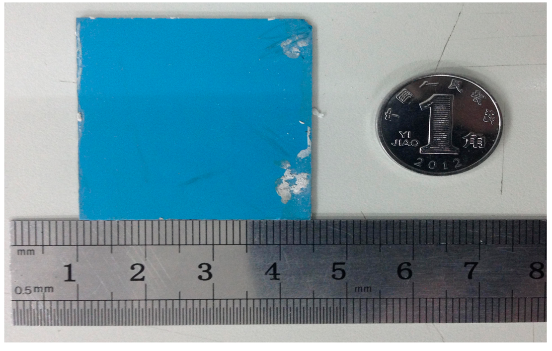
The final stack was placed into a box furnace for sintering for approximately 110 min at 450 °C, which was beneficial to bake off the organics. The fugitive film is volatile around 800 °C, and at the same time, the ceramic is in the porous state. Therefore, gas components can be excluded during the reaction. The heating rate at 800 °C (approximately 0.8 °C/min ramp rate) was reduced in the sintering process, which can make the fugitive film fully burn with oxygen. The highest sintering temperature was 850 °C, and the dwell time of the highest temperature was approximately 30 min. Finally, the ceramic substrate completed the solid-phase reaction, and the fugitive film burned completely to form a sealed cavity, as shown in Figure 3d. In the sintering process, the furnace temperature was strictly controlled, and the specific sintering temperature curve is illustrated in Figure 4. An image of the fabricated embedded wireless passive sensor is shown in Figure 5.
4. Results and Discussion
The electrical parameters of the sensor were obtained by an E4991A impedance analyzer, and the experimental results are listed in Table 2. The values in Table 2 are approximately in good agreement with theoretical calculations.
High-temperature characterization of the sensor was conducted using a high-temperature sintering furnace to simulate a high-temperature environment. The temperature of the sintering furnace was controlled by a computer to ensure the heating rate and constant-temperature time. The sensor and antenna were separated by a distance through a heat insulation device, which is made of an inorganic nanometer refractory insulating material. Therefore, the sensor, which was placed in the furnace interior, can operate in high-temperature environments for signal collection, and the reader antenna, which was placed outside the furnace and connected to the E4991A Agilent impedance analyzer, can operate at room temperature for signal readout. The high-temperature measurement system is shown in Figure 6.
Figure 7 shows the resonance frequencies of the sensor measured at atmospheric pressure from room temperature to 600 °C, and the resonance frequency of the sensor exhibits a slight change as the temperature increases. From the high-temperature performance test, we can conclude that the sensor can obtain a frequency signal in a high-temperature environment, which verifies the stability and availability of the sensor in high-temperature environments. Further, the average slope of the sensor is approximately −0.75 kHz/°C from room temperature to 600 °C, which is smaller than the previous LTCC pressure sensor studied by Xiong in 2013 [10]. In addition, the smaller frequency drift in a high-temperature environment will be more conducive to reducing errors caused at high temperature and obtaining a real pressure signal in high-temperature pressure environments.
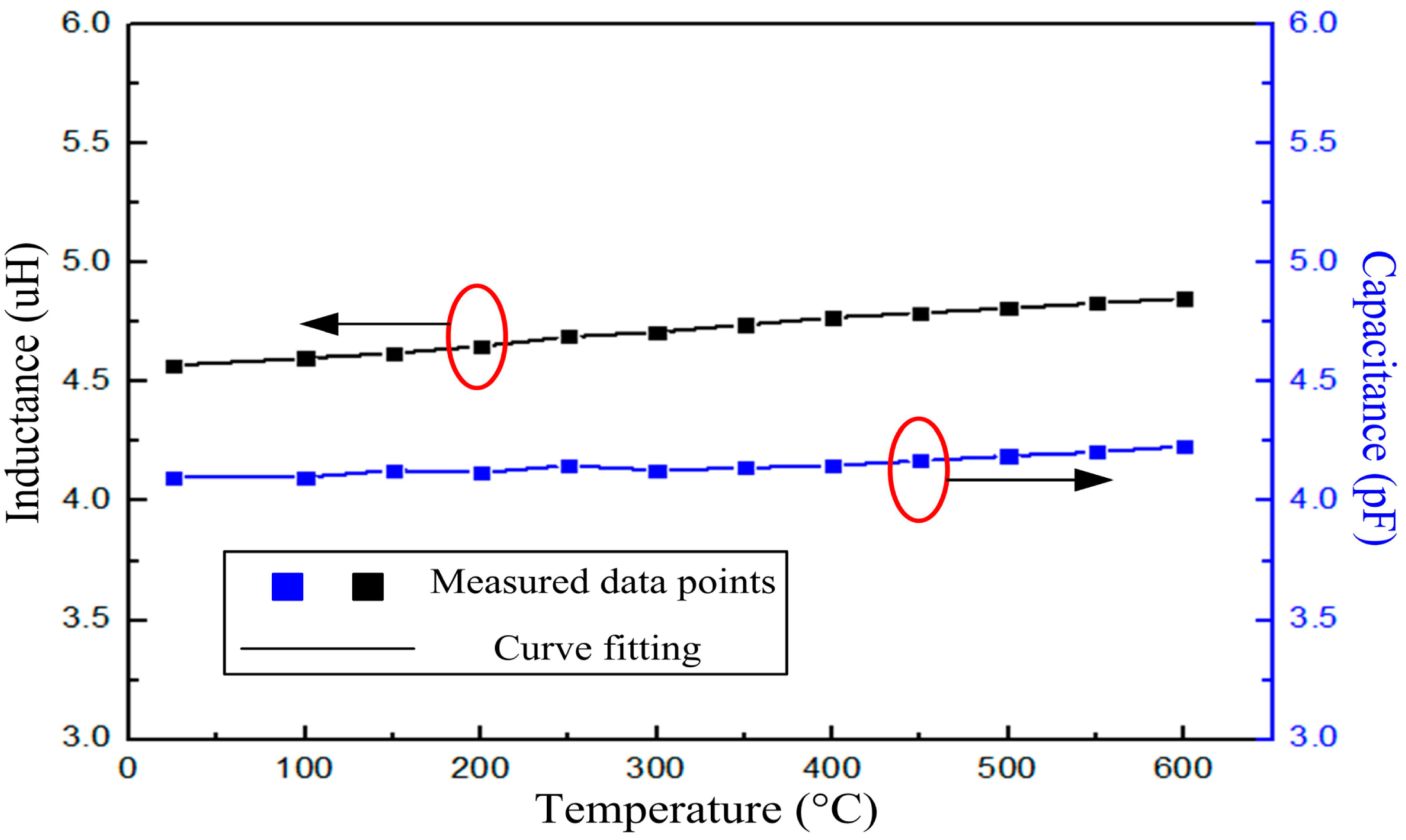
The inductor fabricated with the same structural parameters as the sensor was tested individually, and the inductance versus temperature is shown in Figure 8. According to the formula f = 1/(2π(LC)1/2), the capacitance of the sensor can be calculated from the measured resonant frequency and inductance, which is shown in Figure 8, from where we can conclude that the capacitance has little effect on the resonant frequency of the sensor. The reason is that the capacitance is designed to be embedded, and there is no ceramic dielectric between the capacitance plates. As the temperature increases, the relative permittivity has little effect on the capacitance in elevated temperature environments.
After the high-temperature characterization test, the sensor was tested to measure its pressure response using a high-pressure testing platform, which consists of an E4991A impedance analyzer and a pressure tank, as shown in Figure 9. In addition, the pressure can be controlled from atmospheric pressure up to 100 bar. The fabricated sensor was placed inside the testing system platform, and the antenna was connected to the E4991A impedance analyzer to complete the high-pressure testing. The normalized shifted resonant frequency of the sensor can be calculated from the following expression:
In the actual application environment, the application space of the sensor can be very small. To further reduce the size of the sensor, an embedded multi-layer-inductor sensor can be envisioned, where the inductance coil can be arranged in a three-dimensional coil to form a solenoid shape. Additionally, the high temperature ceramic can be used for the fabrication of the sensor, which can increase the working temperature of the sensor.
5. Conclusions
A high-performance noncontact wireless passive high-temperature pressure sensor has been successfully demonstrated in this paper. The structure of the sensor was optimized, which allows the sensor to operate in high-pressure environments and with a small temperature drift in high-temperature environments. A sealed cavity, inductance coil, and parallel capacitor plates were embedded into the ceramic substrate, which was fabricated using LTCC technology. The fabricated sensor was tested using high-temperature and high pressure system platforms, and the experimental results showed that the frequency drift of the sensor versus temperature is approximately 0.75 kHz/°C, which is far lower than previous LTCC pressure sensors. In addition, the responsivity of the sensor can be up to 31 kHz/bar within the pressure range from atmospheric pressure to 60 bar. In the future, the sensor will ultimately be tested in high-temperature pressure environments to faithfully register pressure variations in the automotive, aerospace, and aeronautics fields.
Acknowledgments
This work was supported by the National Science Fund for Distinguished Young Scholars (No. 51425505), the National Natural Science Foundation of China (No. 61471324) and the Program for the Outstanding Innovative Teams of Higher Learning Institutions of Shanxi, Research Project Supported by Shanxi Scholarship Council of China (2013-077).
Author Contributions
All works with relation to this paper have been accomplished by all authors' efforts. The idea and design of the sensor were proposed by Chen Li and Qiulin Tan. Chenyang Xue designed the fabrication method of the sensor. Wendong Zhang and Yunzhi Li gave significant guidance on the experiments. At last, every segment relate to this paper is accomplished under the guidance from Jijun Xiong.
Conflicts of Interest
The authors declare no conflict of interest.
References
- Johnson, R.W.; Evans, J.L.; Jacobsen, P.; Thompson, J.R.; Christopher, M. The changing automotive environment: High-temperature electronics. IEEE Trans. Electron. Packag. Manuf. 2004, 27, 164–176. [Google Scholar]
- Prosser, S.J. Advances in sensors for aerospace applications. Sens. Actuators A Phys. 1993, 37–38, 128–134. [Google Scholar]
- George, T.; Son, K.A.; Powers, R.A.; del Castillo, L.Y.; Okojie, R. Harsh Environment Microtechnologies for NASA and Terrestrial Applications. Proceedings of IEEE Sensors, Irvine, CA, USA, 30 October–3 November 2005; pp. 1253–1258.
- Li, X.; Liu, Q.; Pang, S.X.; Xu, K.X.; Tang, H.; Sun, C.S. High-temperature piezoresistive pressure sensor based on implantation of oxygen into silicon wafer. Sens. Actuators A Phys. 2012, 179, 277–282. [Google Scholar]
- San, H.S.; Li, Y.; Song, Z.J.; Yu, Y.X.; Chen, X.Y. Self-Packaging Fabrication of Silicon–Glass-Based Piezoresistive Pressure Sensor. IEEE Electron Device Lett. 2013, 34, 789–791. [Google Scholar]
- San, H.S.; Zhang, H.; Zhang, Q.; Yu, Y.X.; Chen, X.Y. Silicon–Glass-based single piezoresistive pressure sensors for harsh environment applications. J. Micromech. Microeng. 2013. [Google Scholar] [CrossRef]
- Liu, Q.M.; Du, L.D.; Zhao, Z.; Xiao, L.; Sun, X.J. Localized Si–Au eutectic bonding around sunken pad for fabrication of a capacitive absolute pressure sensor. Sens. Actuators A Phys. 2013, 201, 241–245. [Google Scholar]
- Yang, J. A silicon carbide wireless temperature sensing system for high temperature applications. Sensors 2013, 13, 1884–1901. [Google Scholar]
- Fonseca, M.A.; English, J.M.; Arx, M.; Allen, M.G. Wireless micromachined ceramic pressure sensor for high-temperature applications. J. Microelectromech. Syst. 2002, 11, 337–343. [Google Scholar]
- Birdsell, E.D.; Park, J.; Allen, M.G. Wireless Ceramic Sensors Operating in High Temperature Environment. Proceedings of 40th ALAA/ASME/SAE/ASEE Joint Propulsion Conference, Fort Lauderdale, FL, USA, 11 July 2004.
- Xiong, J.J.; Li, Y.; Hong, Y.P.; Zhang, B.Z.; Cui, T.H.; Tan, Q.L.; Zheng, S.J.; Liang, T. Wireless LTCC-based Capacitive Pressure Sensor for Harsh Environment. Sens. Actuators A Phys. 2013, 197, 30–37. [Google Scholar]
- Li, C.; Tan, Q.L.; Xiong, J.J.; Jia, P.G.; Hong, Y.P.; Ren, Z.; Luo, T.; Liu, J.; Xue, C.Y.; Zhang, W.D. A noncontact wireless passive radio frequency (RF) resonant pressure sensor with optimized design for applications in high-temperature environments. Meas. Sci. Technol. 2014. [Google Scholar] [CrossRef]
- Chen, P.J.; Saati, S.; Varma, R.; Humayun, M.S.; Tai, Y.C. Wireless Intraocular Pressure Sensing Using Microfabricated Minimally Invasive Flexible-Coiled LC Sensor Implant. J. Microelectromech. Syst. 2010, 19, 721–734. [Google Scholar]
- Mohan, S.S.; Hershenson, M.M.; Boyd, S.P.; Lee, T.H. Simple accurate expressions for planar spiral inductances. IEEE J. Solid-State Circuits 1999, 34, 1419–1424. [Google Scholar]


| Symbol | Parameter | Value |
|---|---|---|
| a | Radius of the capacitance plate metal | 4 mm |
| tg | Height of the embedded cavity | 110 μm |
| tm | Thickness of the sensitive membrane | 440 μm |
| din | Diameter of the inner inductor | 9.8 mm |
| dout | Diameter of the outer inductor | 22.5 mm |
| n | Number of coil turns | 15 |
| ls | Width of the coil turns | 0.4 mm |
| Symbol | Parameters | Value |
|---|---|---|
| L | Inductance | ∼4.5 μH |
| R | Resistance | ∼6.1 Ω |
| C | Capacitance | ∼4.1 pF |
| f | Resonant frequency of the sensor | ∼37.5 MHz |
© 2014 by the authors; licensee MDPI, Basel, Switzerland. This article is an open access article distributed under the terms and conditions of the Creative Commons Attribution license ( http://creativecommons.org/licenses/by/4.0/).
Share and Cite
Li, C.; Tan, Q.; Xue, C.; Zhang, W.; Li, Y.; Xiong, J. A High-Performance LC Wireless Passive Pressure Sensor Fabricated Using Low-Temperature Co-Fired Ceramic (LTCC) Technology. Sensors 2014, 14, 23337-23347. https://doi.org/10.3390/s141223337
Li C, Tan Q, Xue C, Zhang W, Li Y, Xiong J. A High-Performance LC Wireless Passive Pressure Sensor Fabricated Using Low-Temperature Co-Fired Ceramic (LTCC) Technology. Sensors. 2014; 14(12):23337-23347. https://doi.org/10.3390/s141223337
Chicago/Turabian StyleLi, Chen, Qiulin Tan, Chenyang Xue, Wendong Zhang, Yunzhi Li, and Jijun Xiong. 2014. "A High-Performance LC Wireless Passive Pressure Sensor Fabricated Using Low-Temperature Co-Fired Ceramic (LTCC) Technology" Sensors 14, no. 12: 23337-23347. https://doi.org/10.3390/s141223337
APA StyleLi, C., Tan, Q., Xue, C., Zhang, W., Li, Y., & Xiong, J. (2014). A High-Performance LC Wireless Passive Pressure Sensor Fabricated Using Low-Temperature Co-Fired Ceramic (LTCC) Technology. Sensors, 14(12), 23337-23347. https://doi.org/10.3390/s141223337