Abstract
This paper deals with the fractional order control for the complex systems, hand exoskeleton and sensors, that monitor and control the human behavior. The control laws based on physical significance variables, for fractional order models, with delays or without delays, are proposed and discussed. Lyapunov techniques and the methods that derive from Yakubovici-Kalman-Popov lemma are used and the frequency criterions that ensure asymptotic stability of the closed loop system are inferred. An observer control is proposed for the complex models, exoskeleton and sensors. The asymptotic stability of the system, exoskeleton hand-observer, is studied for sector control laws. Numerical simulations for an intelligent haptic robot-glove are presented. Several examples regarding these models, with delays or without delays, by using sector control laws or an observer control, are analyzed. The experimental platform is presented.
1. Introduction
The IHRG is an intelligent haptic robotic glove system for the rehabilitation of patients that have a diagnosis of a cerebrovascular accident. This system is created by a thin textile in order to have a comfortable environment for grasping exercises. An exoskeleton architecture ensures the mechanical compliance of human fingers. The driving and skin sensor system is designed to determine comfortable and stable grasping function. This paper analyzes the dynamics of an exoskeleton hand using fractional order operators and proposes control solutions.
The number of applications in the system modelling, where the fractional order calculus (FOC) is used, has increased significantly in the last few decades. Many authors proved that non-integer order integrals and derivatives are suitable for analyses of the properties of various materials. Recent achievements in the interpretation of FOC operators allowed to apply FOC for processes that are better described by fractional order models (FOM) rather than integer order models (IOM). The role of these models in soft matter physics and viscoelastic behavior, in the theory of complex materials, its quality to include effects with non-conservative forces and power-law phenomena suggest to describe the complexity of human dynamics using FOM operators [1].
The idea is supported by the evidence of dynamics in muscles and joint tissues throughout human musculo-skeletal system [2,3]. Interaction and dependence between biological systems and associated mechanical components was analyzed in [4,5,6]. Fractional order models for metal polymer composite was discussed in [7]. In [8,9] viscoelastic properties for a large variety of biological entities were studied. A class of sensors based on fractional calculus was presented in [10]. Optimal techniques using fractional calculus for sensor networks were discussed in [11]. A fractional model to capture muscular dynamics in the movement process was proposed in [12]. In [13,14,15] a class of neural, muscular, and vascular processes were studied to minimize sensor placement. Recently, there is a great deal of interest in so-called rehabilitation robotics, a branch of the areas of robotics and mechatronics that addresses the study of complex robotic systems aiming to restore human functions for those who suffer major trauma as a result of strokes and cerebrovascular accidents. Robotic therapy is a promising form of neurorehabilitation that can be delivered in more intensive regimens compared to conventional therapy [16]. The complexity of these systems associated with a specified class of sensors is well described by fractional order differential equations [17,18]. The methods for the analysis and design of fractional order operators can be found in [19]. Control and stability of FOM was investigated by techniques Lyapunov in [20,21]. In particular, the authors of [22,23] discuss the stability properties of solutions of nonlinear Caputo fractional differential equations. The exponential stability of nonlinear FOM using the Lyapunov method was analyzed in [24,25]. Other control problems for a class of FOMs with delay were rigorously investigated in [26,27]. Reference [28] proposed an observer for a class of linear and nonlinear FOM using Lyapunov methods. To our knowledge, this paper is the first paper to assess FOM for systems and sensors that monitor or control human behavior. The exoskeleton architecture, which ensures a mechanical compliance of human fingers, including the driving and sensor system, determines comfortable and stable grasping functions.
The dynamics of the whole system, exoskeleton hand (EXHAND), and the sensors can be accurately described by FOM operators. A class of 3D FOM bending sensors is analyzed. The control laws based on physical significance variables, for linear and delay FOM or IOM systems, are proposed and discussed. The sector control laws for linear FOM, with delays or without delays are studied. Lyapunov techniques and the methods that derive from Yakubovici-Kalman-Popov Lemma are used, and the frequency criteria that ensure asymptotic stability of the physical significance variable closed loop system are inferred. An observer control is proposed for the complex models, EXHANDs and sensors. The asymptotic stability of the whole system, the observer-system, is studied according to sector control laws. Frequency criteria and conditions for asymptotic stability are determined. Numerical simulations for the intelligent haptic robot-glove (IHRG) are presented. Several examples regarding the FOM or IOM systems, with delays or without delays, by using sector control laws or an observer control, are analyzed. The IHRG experimental platform is then discussed.
The paper is structured as follows: Section 2.1 discusses FOM sensors and FOM systems implemented in EXHAND; Section 2.2 presents the control systems; Section 3.1 analyzes IHRG numerical simulations; and Section 3.2 presents the IHRG platform. Section 4 provides concluding remarks and discussions.
2. Methods
2.1. Fractional Order Models
Notations:
- The fractional order integral of order β is the Riemann-Liouville fractional integral:
- The Caputo derivative of order is:where is the fractional order exponent and is the gamma (Euler’s) function.
(a) 3D curvature sensors described by FOM
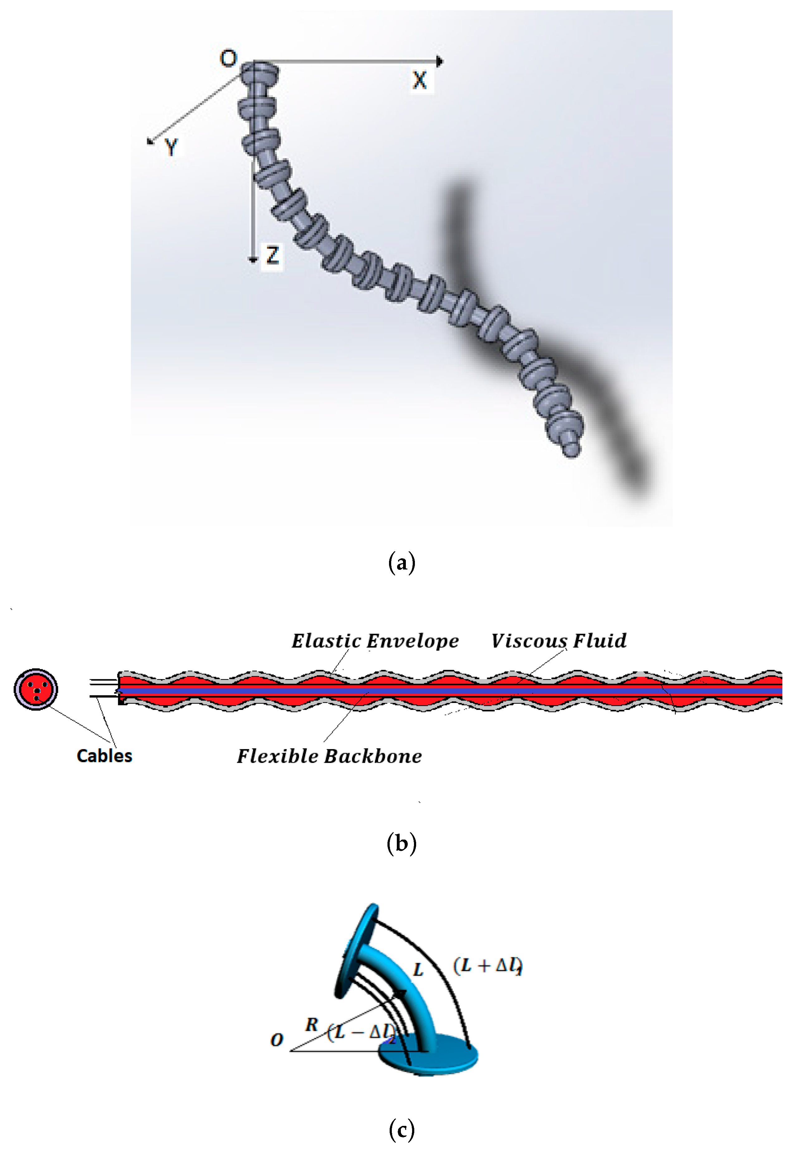
Bending sensors represent a class of sensors with large applications in the control of complex systems. They convert changes in bend to an electrical parameter variation. Conventional bending sensors handle cases in which bending is produced in the 2D plane. The most common are the resistive sensors, described by IOM operators of order 0. For a special class of systems, such as the hyper-redundant robots [29] where bending is produced in a 3D space (Figure 1a), a special class of bending sensors defined by FOM operators (Figure 1b) is used.
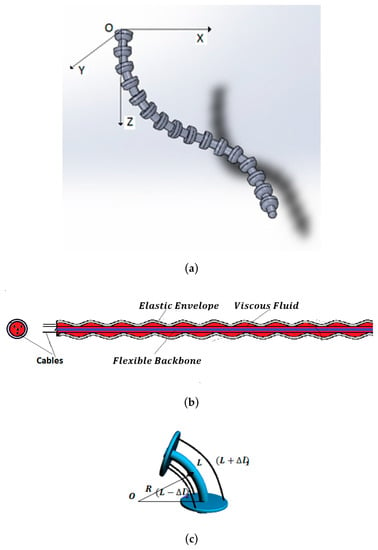
Figure 1.
(a) 3D hyper-redundant robotic arm. (b) 3D FOM curvature sensor. (c) Measurement technique.
The architecture of this sensor consists of a main viscoelastic component determined by a long flexible backbone wrapped in a cylindrical elastic envelope. Three antagonist cables are implemented at the periphery of the system. In static behavior, curvature is obtained by the differential measurement of the cable lengths, Figure 1c [30]:
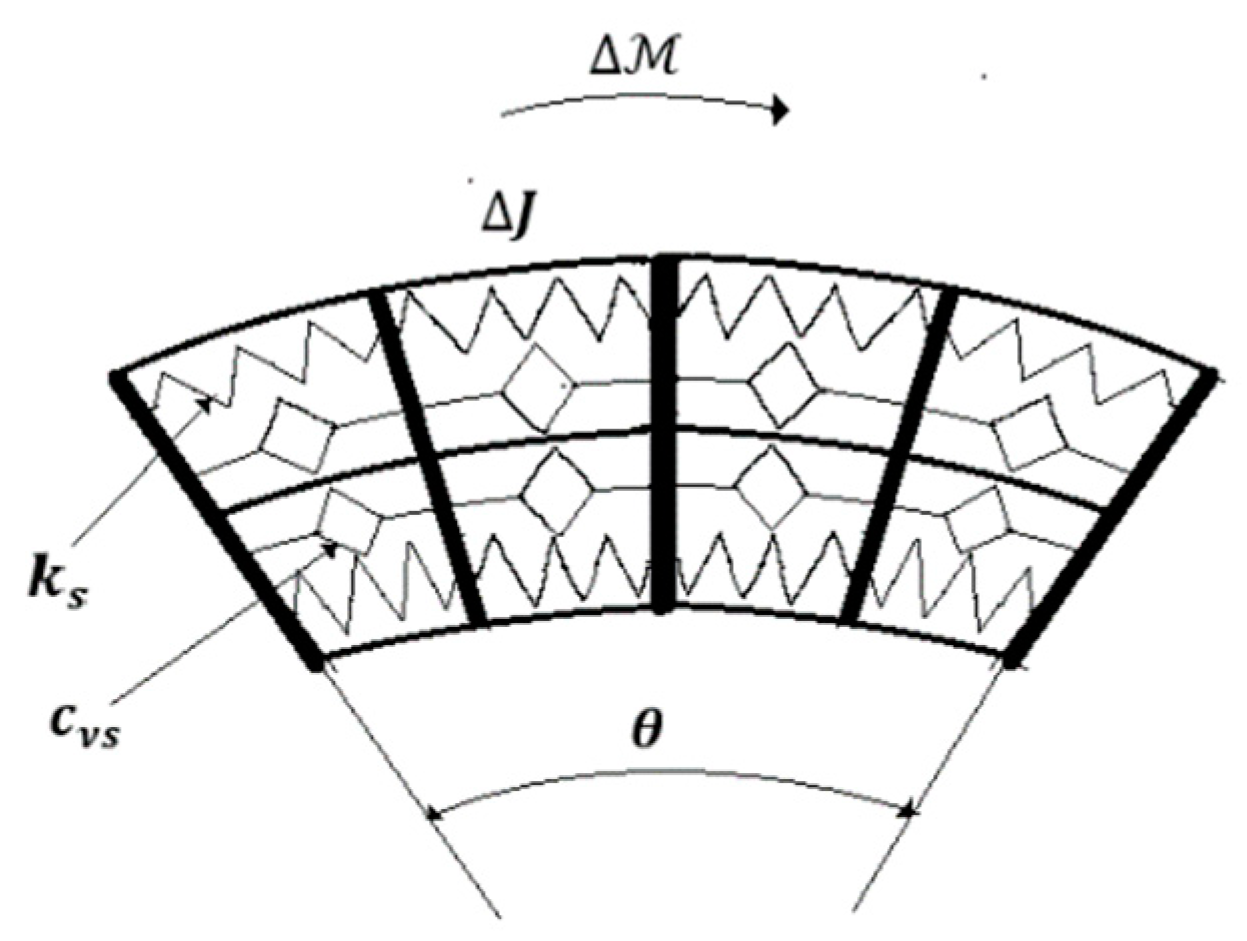
The dynamic behavior is inferred considering constant curvature along the length. Employing the same technique as that developed in [17] yields (Figure 2):
where are distributed viscous and elastic coefficient, assumed uniform distributed along the length, are material parameters and is the moment that determines the bending. The transfer function is derived from Equation (2) as:
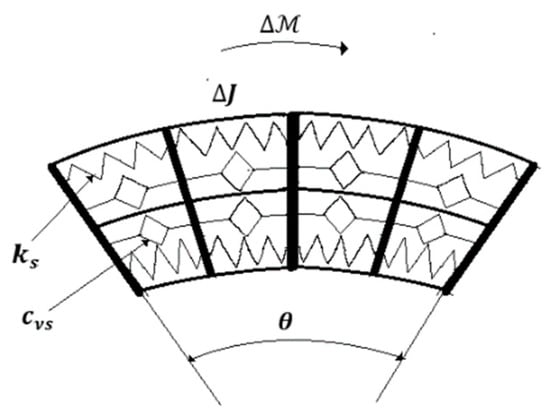
Figure 2.
Technological equivalent model of the 3D curvature sensor.
That corresponds to an order 2 FOM operator.
(b) FOM systems
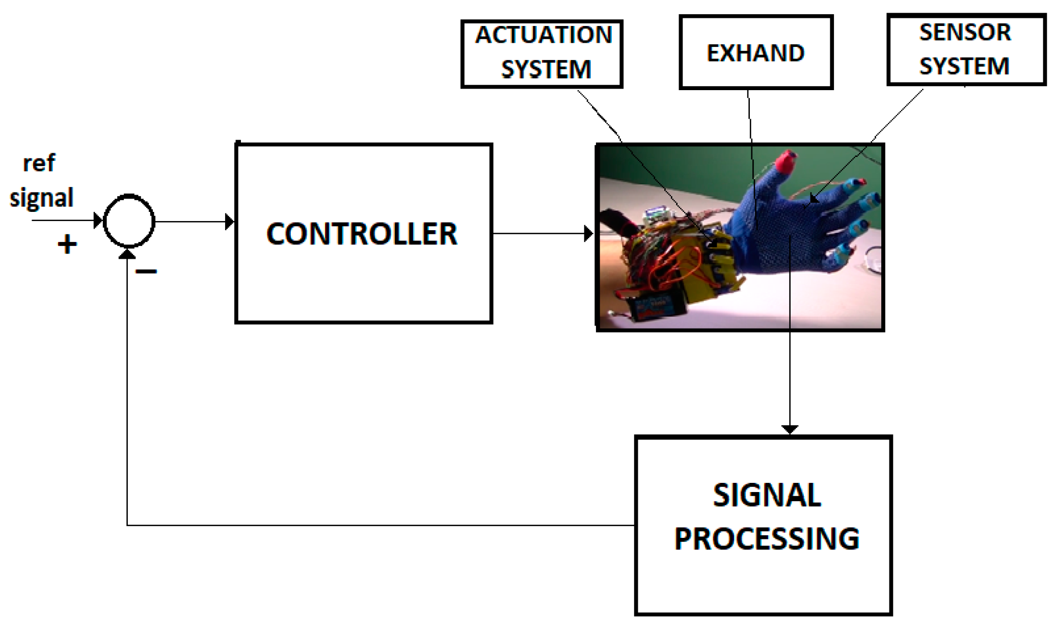
A large class of systems that monitors or controls the human behavior is well described by the FOM operators. Figure 3 shows the control system of an intelligent haptic robot-glove (IHRG) for the rehabilitation of patients that have a diagnosis of a cerebrovascular accident. The IHRG is a medical device that acts in parallel to a hand in order to compensate for lost functions [16]. The exoskeleton architecture that ensures the mechanical compliance of human fingers for the driving system determines comfortable and stable grasping functions.
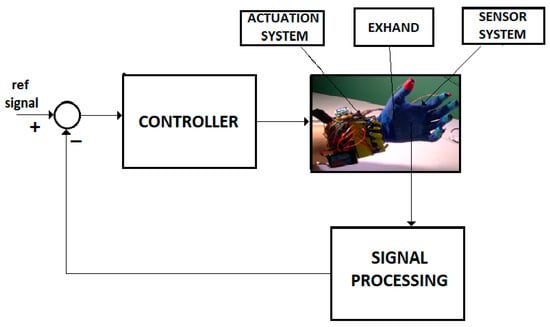
Figure 3.
IHRG system.
The dynamics of the system (EXHAND) can be accurately described by FOM operators,
where is the state vector that defines the motion parameters, β is the fractional order exponent, and are constant matrices. In a FOM operator of EXHAND, the vector components are defined as
The nonlinear term is determined by the gravitational components and satisfies the inequality
The output of the system is generated by the bending sensors. Provided that the bending of the phalange musculoskeletal system is in 2-D plane, in this project, we used an Arduino Flex Resistive Sensor network. This sensor operates as a zeroth IOM operator,
where is a constant vector.
A new model can be inferred if the delay time constant, associated with the neuro-muscular system, the driving system and the processing time, is introduced,
The initial conditions are defined by
where the function is associated to initial states.
For Equations (4)–(8) we used the control system from Figure 4 with a FOM operator for the EXHAND and a IOM operator for the sensor system.

Figure 4.
Control system.
2.2. Control Systems
Mathematical Preliminaries
Lemma
[19]. For any symmetric matrix , the following inequality holds:
where denote the minimum and maximum eigenvalue, respectively, of matrix and is the unit matrix.
Theorem 1
([21,22,24]). The system , is asymptotically stable if
Theorem 2
([22,23,24]). The system is asymptotically stable if there exists a continuously differentiable function that satisfies
where are positive constants,
2.2.1. Control for the EXHAND Without Delays
Consider the system from Figure 4 defined by Equations (4)–(7) without a delay time. Assume a control law.
where the control gain k verifies the condition
where σ is a positive constant (for simplicity, ).
Remark 1.
For the EXHAND model with the state variables defined by Equation (5) and the output vector, the control law (Equation (10)) becomes alaw
or
If c is selected as, the control becomes a PD law
Control System 1.
The system (Equations (4)–(7)) with the controller defined by Equations (13) and (14) is asymptotically stable if:
The matrix is Hurwitz stable where .
where , and , P are solutions of the Lyapunov equation [20,29].
Proof.
Consider the Lyapunov function
where . The first asymptotic stability conditions (Equation (8)) are verified for , [21] (Theorem 1), where denote the minimum and maximum eigenvalues of P. The fractional derivative of Equation (14) will be [22,24],
By substituting Equation (4) into Equation (20), one derives
Employing the condition (a) yields
Considering Equations (13) and (14), this inequality becomes
By employing the condition (Equation (15)) and Yakubovici-Kalman-Popov (YKP) Lemma [31], results
Now, considering the control law (Equation (13)), it follows that
or, by Equation (16),
where
□
2.2.2. Control for the EXHAND with Delay
Control System 2.
The system described by Equation (8) with the control law defined by Equation (13) is asymptotically stable if:
1. is Hurwitz stable, where
where , are solutions of the Lyapunov equations and
Proof.
Consider the following Lyapunov function:
where are are positive definite and symmetrical matrices, . satisfies the condition (Equation (11)) of Theorem 2.
The derivative is computed from:
where is the Riemann-Liouville fractional integral of the order The derivative is evaluated from Equation (32)
which leads to the inequality
By evaluating Equation (37) along of solutions of Equation (8) it turns out that
By applying the control law Equation (28), it yields
The following inequality will be used [23]
Additionally, considering the YKP Lemma as in the previous Control System, yields
Substituting this result into Equation (39), considering the inequalities of Equations (6) and (40), one derives that
Employing Equations (30) and (31), yields
Denoted by
and from Equation (35) results
□
2.2.3. Control System with Observer for the EXHAND with Delay
Consider the linearized model of Equation (8) rewritten as
where the nonlinear term was approximated by
Remark 2.
For the EXHAND model, the pair (is controllable and the pairis observable.
Consider the system defined by Equation (46). The following observer is proposed:
where is the observer state, is the estimated output and are observability vectors. The observer error is
defined by the following equation:
Consider the control law
The global state is considered for the system “EXHAND-observer”.
Control System 3.

The whole system, “EXHAND-observer”, Equations (46), (47), and (49)–(51) (Figure 5) with the control law (55), is asymptotically stable if

Figure 5.
Control system with observer.
is Hurwitz stable where
where is defined by Equation (50) and
Proof.
Consider the Lyapunov function
where are are positive definite and symmetrical matrices. satisfies the first condition (Equation (11)) of Theorem 2.
Applying the same procedures as in the previous control system, yields
By employing conditions (58)–(61) this inequality becomes
and using (53) yields
□
Remark 3.
The asymptotical stability conditions of Control System 2, Control System 3 are independent by the time delay
3. Results
3.1. IHRG Control—Numerical Simulations
3.1.1. EXHAND with Sensors Without Delays
Consider the IHRG system of Figure 3. The exoskeleton drive system is a decoupled one, for each finger. The following parameters of the hand and exoskeleton mechanical architecture [16] will be used: the equivalent moment of inertia is , the equivalent mass is the viscous and elastic coefficients of the equivalent Kelvin-Voigt model of the joint tissues throughout phalange musculoskeletal system and exoskeleton are [6,7] , respectively, and the damping coefficient is .
where the nonlinear component verifies the inequality (Equation (6)) for . The sensor is considered as an IOM operator and the output is defined as
The fractional order exponent is . The FOM model (Equations (8) and (9)) is defined as ; ; ; .
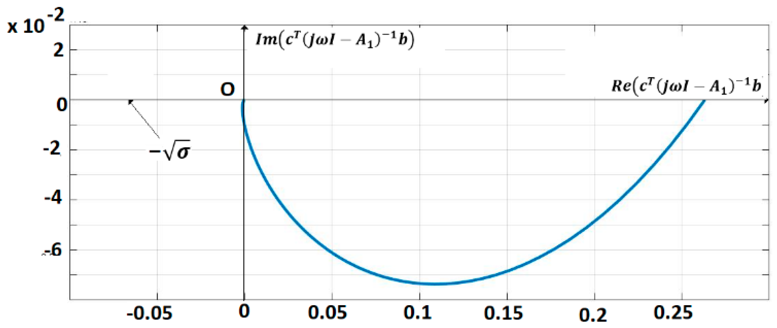
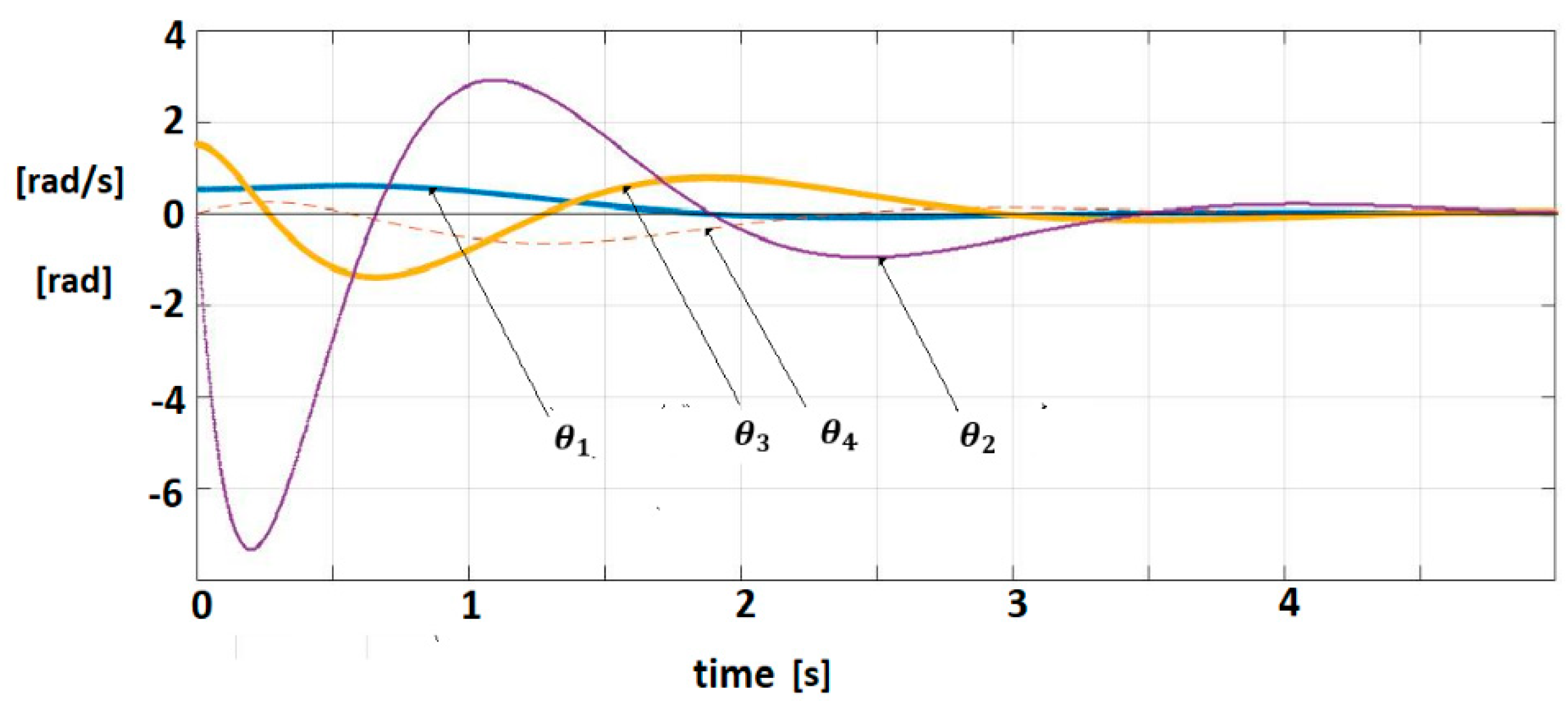
The pairs are controllable, respectively observable. The IOM sensor output without delays is given by (7). A control law (Equation (13)) (for = 0) with is applied. This control verifies the sector constraint (Equation (11)) with . The matrix R was considered as, where is Hurwitz stable. The vector and a matrix were inferred with . The polar plot of is shown in Figure 6. The closed-loop system satisfies the frequential criterion (Equation (17)), condition (18) is verified for MATLAB/SIMULINK and techniques based on the Mittag-Leffler functions are used for the simulation [1,2]. Figure 7 shows the trajectories of fractional order variables.
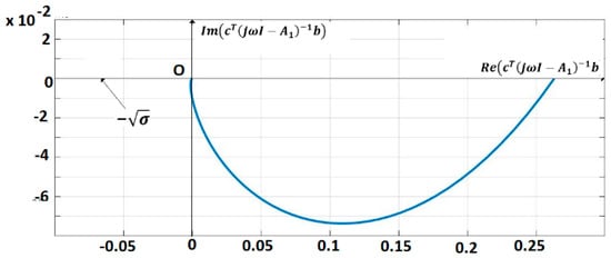
Figure 6.
Polar plot of
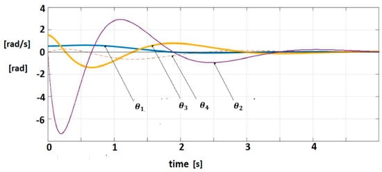
Figure 7.
Fractional-order variable trajectories for FOM system with IOM sensor.
The steady state behavior can be analyzed by using by transfer function of Equations (65)–(67) (linearized model)
The control law (Equation (13)) can be rewritten as a PD control
and the controller transfer function will be
For the PD0.5 control law, we have
The steady error can be inferred from Equations (71)–(73) as [21,32,33]
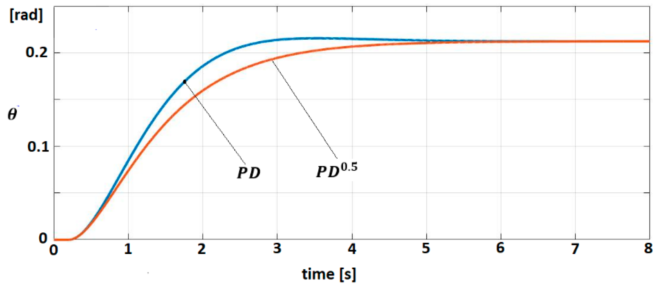
The behavior of the linearized model (Equation (68)) for both control laws (Equations (73) and (74)) is studied. The trajectories of angular position for target signal are shown in Figure 8.
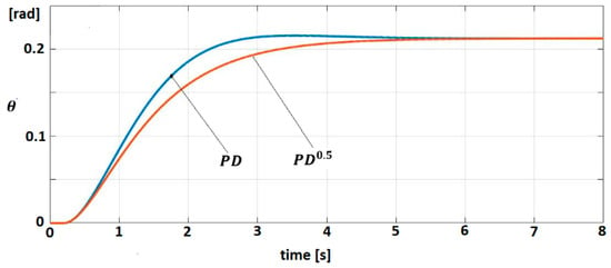
Figure 8.
Trajectory for PD0.5 and PD
3.1.2. EXHAND with Delay
The sensor dynamics are
where Substituting Equations (74) and (75) into (68) and using the control law (Equation (70)), yields
with initial conditions
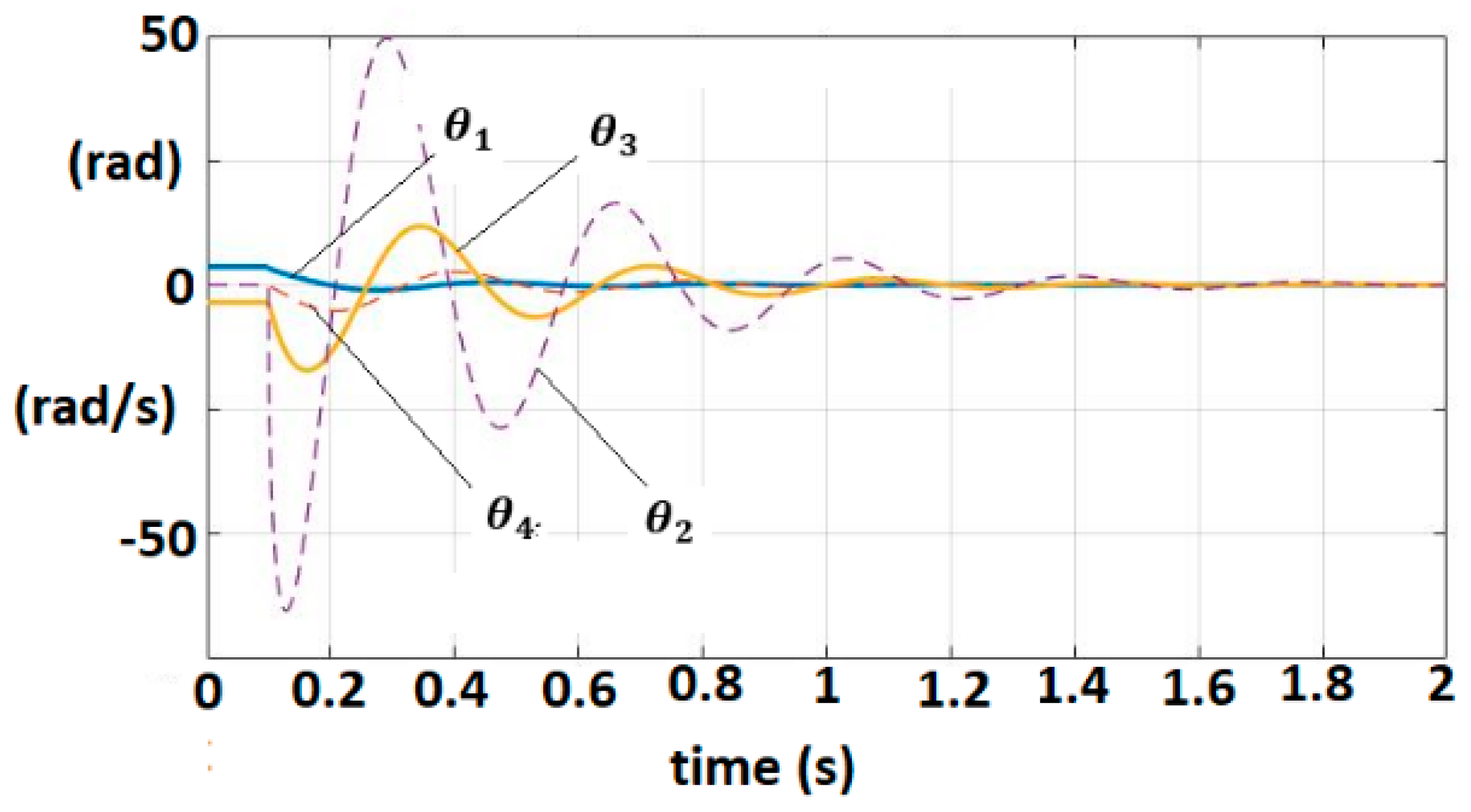
The delay component of the dynamic model is defined by The controller parameters are selected as that satisfy Equations (29)–(31) by employing the same parameters for as in the previous example. The evolution of the fractional order variables is shown in Figure 9.
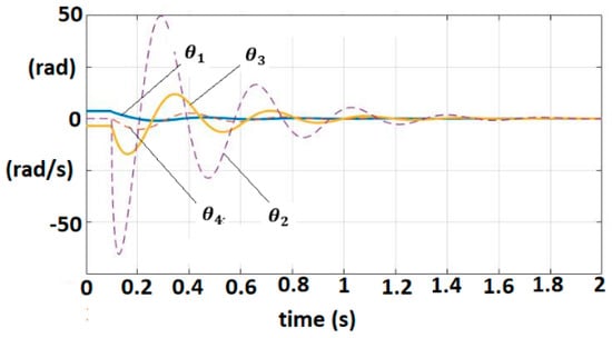
Figure 9.
Fractional-order variable trajectories for FOM EXHAND with delay.
3.1.3. EXHAND with Delay and Observer
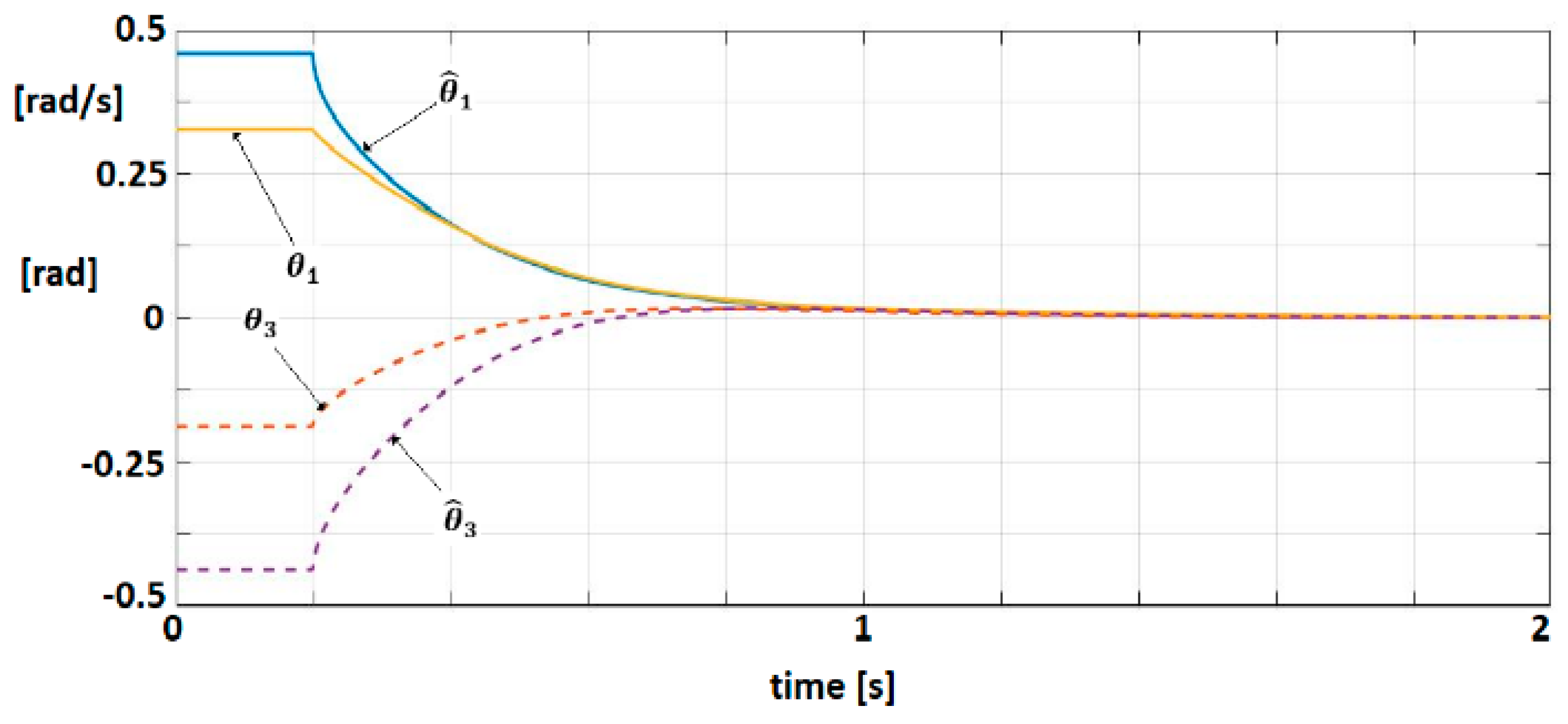
An observer (Equations (49)–(51)) with is associated to the linearized dynamic model. The matrix verifies the condition as to be Hurwitz matrix. For , solution of is obtained with . A control law (55) with were selected. Equations (57)–(61) are easily verified. Figure 10 shows the trajectories of physical significance variables, position and velocity, for the system and observer.
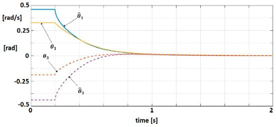
Figure 10.
Trajectories of position and velocity for the system and observer.
3.2. IHRG Experimental Platform
The IHRG is an exoskeleton that supports the human hand and hand activities by using a control architecture for dexterous grasping and manipulation. IHRG is a medical device that acts in parallel to a hand in order to compensate for lost function. It is easy to use and can be a helpful tool in the home [16,34].
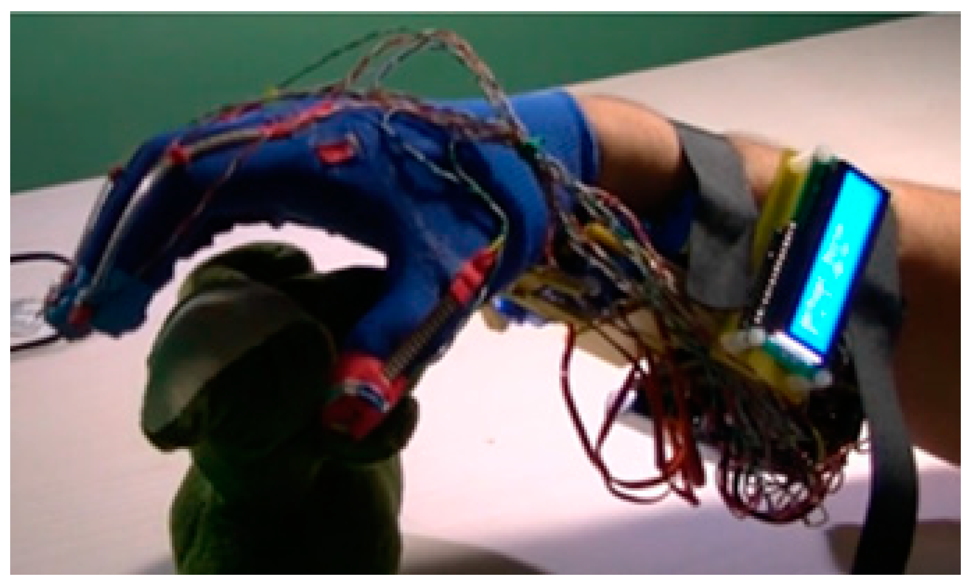
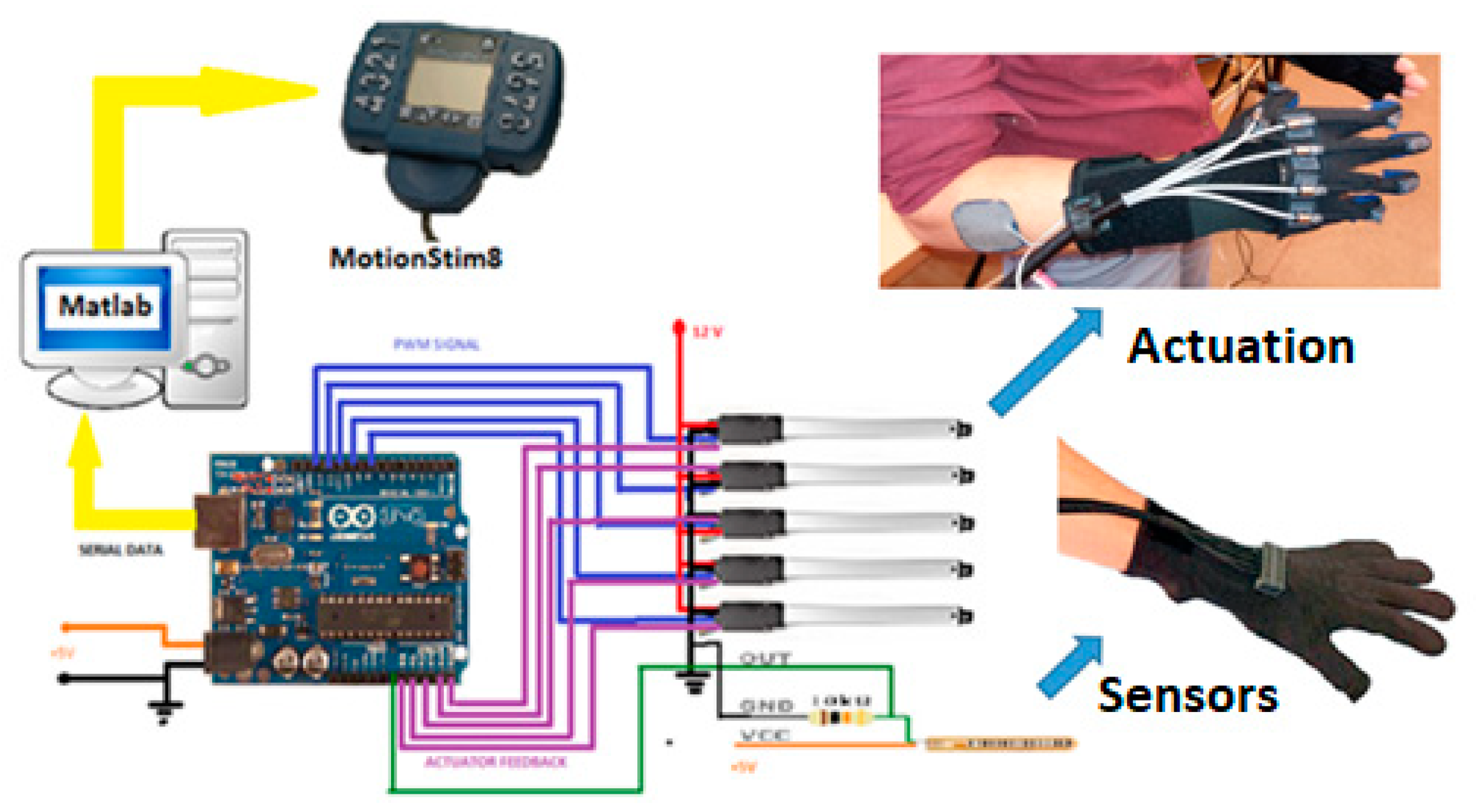
The mechanical architecture consists of articulated serial elements of which design covers functional and anatomic finger phalanges. The glove is created by a thin textile that represents an infrastructure suitable for actuation wires and sensors. A distributed actuation system is used for implementing the operations of the hand. An Arduino Flex Sensor network (with zeroth order sensors) is used to control the motions. An Arduino Mega 2560 hardware platform determines the movement of the glove’s actuators for exercises like opening or closing of the fingers (Figure 11 and Figure 12).

Figure 11.
IHRG-human hand exoskeleton.
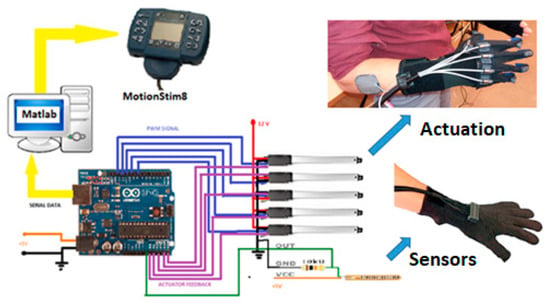
Figure 12.
IHRG general architecture.
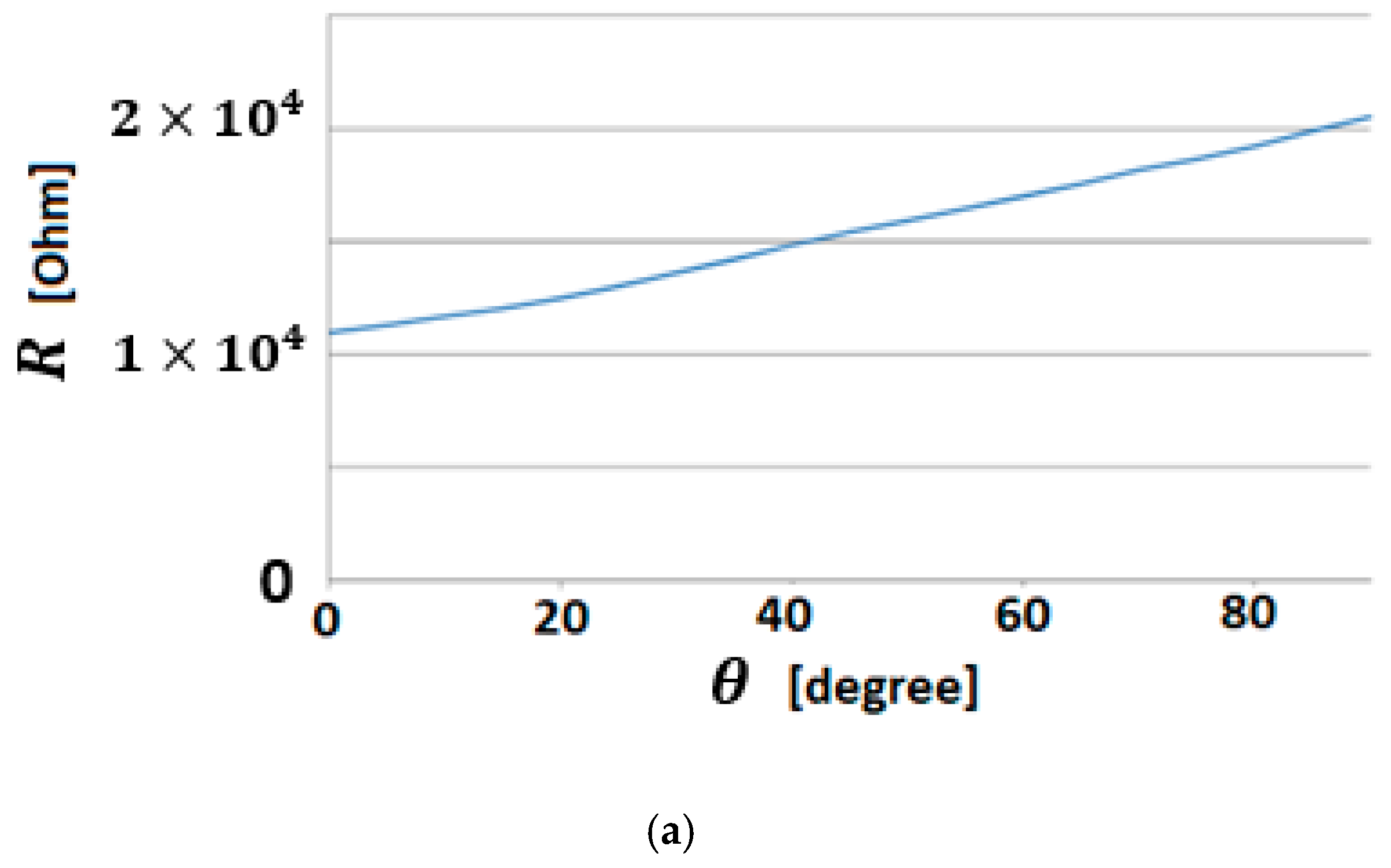
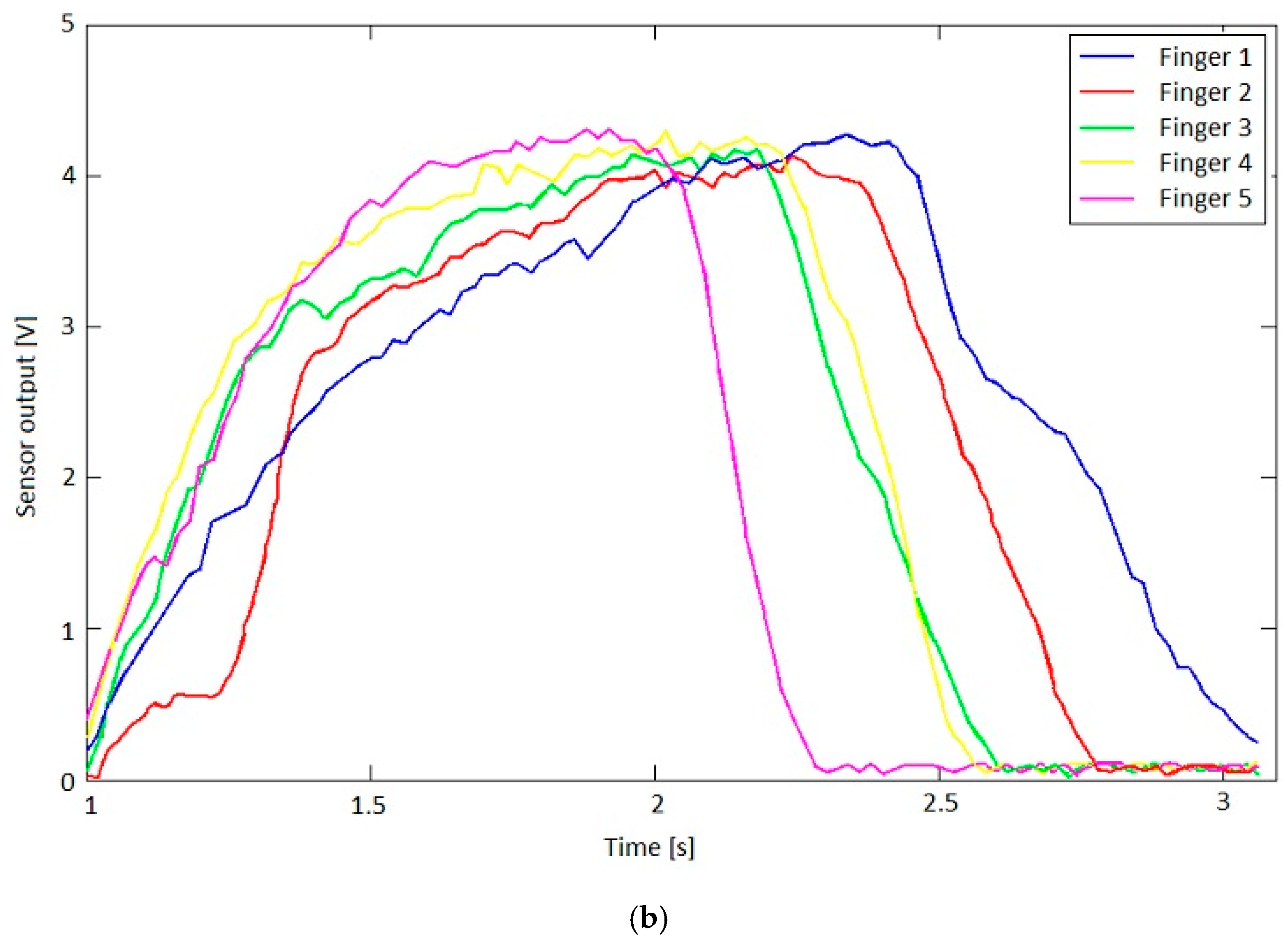
All the movements of the hand are controlled by the software of the hybrid IHRG system, which was developed in MATLAB and Simulink. The performance of each patient following the exercises program can be recorded by the same software. The control system of Control System 1 is implemented. In Figure 13 are shown the sensor signals during an open-close-open hand exercise.
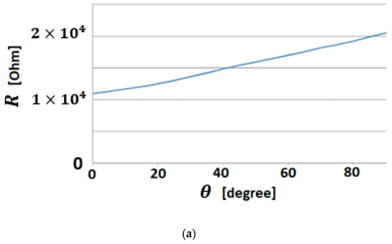
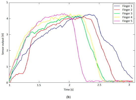
Figure 13.
(a) Bending sensor characteristics; (b) Output values of the bending sensors.
4. Discussion
I. We designed, built, and tested an intelligent haptic robotic glove for the rehabilitation of the patients that have a diagnosis of a cerebrovascular accident. The glove is created by a thin textile in order to have a comfortable environment for the grasping exercises. This thin textile creates an infrastructure suitable for wire actuation and sensors. This exoskeleton architecture ensures the mechanical compliance of human fingers. The driving and skin sensor system is designed to determine comfortable and stable grasping function. The dynamics of the exoskeleton hand are modeled by fractional order operators. To our knowledge, this paper is the first paper in which the interaction between biological systems (human hand) and mechanical associated components (exoskeleton) is analyzed by fractional order models. These new models are used to develop a class of algorithms for the control of the stable grasping function. The control systems are based on the physical significance variable control that are generated by sensor classes implemented in the system. These sensors are also modeled as operators with delays. The paper proposes control solutions and determines the criterions for controller parameter tuning for several classes of models. The observer techniques are also discussed and implemented. The quality and the stability of motion, are analyzed by Lyapunov methods and techniques that derive from Yakubovici-Kalman-Popov Lemma.
Despite of the model complexity, the control systems are very simple, and the controllers are easily implemented in an Arduino Mega 2560 hardware platform. There were many advantages for using this platform since this hardware board has ports for PWM signals that are useful to be sent to the actuators and ports for reading the signals coming from the bending sensors.
In order to help patients to follow an after-stoke recovery program, the system uses a set of predefined rehabilitation exercises like open the hand, close it, try to grab an object or simple wave. The system is very easy to use at home, with minimal training. The predefined rehabilitation set of exercises was created to be used.
II. The control systems discussed in the previous sections are focused on the control problems of the IHRG system, where the EXHAND model is described by FOM operators and the sensor system is based on zeroth order sensors. These control solutions can be also used for a larger class of complex systems as hyper-redundant systems, that use complex FOM sensors (Figure 14).

Figure 14.
Control system with FOM sensors.
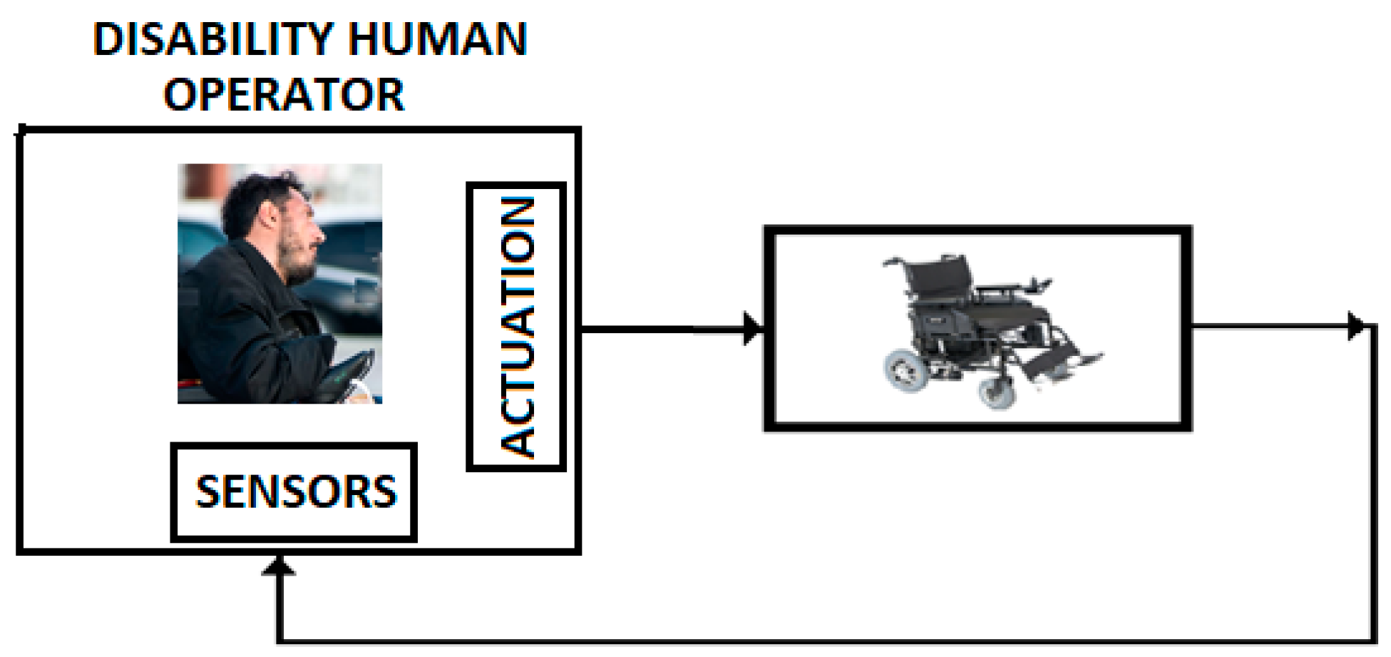
III. In addition, we consider that control systems discussed in the previous sections can be applied to a class of control problems associated to the persons with disabilities. Figure 15 presents a wheelchair control system for this class of persons. In this case, the human operator is represented by the persons with hemiparesis/hemiplegia, with motor restriction (arm or leg-emphasized hemiparesis) and with serious brain damage [35],
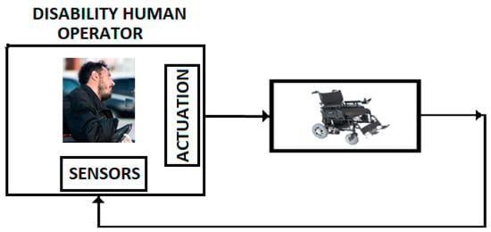
Figure 15.
Control with disability human operator.
The transfer function of this human operator has a model that corresponds to a time delay fractional order model with time constant and fractional order . These parameters are determined by the characteristics of the damaged brain, viscoelastic properties of the atrophied muscles, and propagation time along the nervous terminals.
We consider that these models can be studied by using the techniques developed in this paper.
Author Contributions
Conceptualization, M.I. and N.P.; methodology, N.P. and A.C.; software, D.P.; validation, M.I. and A.C.; formal analysis, M.P.; investigation, M.I.; resources, N.P.; data curation, D.P.; writing—A.C.; writing—review and editing, D.P.; visualization, M.P.; supervision, M.I.; project administration, N.P.; funding acquisition, N.P.
Funding
The authors gratefully acknowledge funding from European Union’s Horizon 2020 Research and Innovation program under the Marie Sklodowska Curie grant agreement No. 813278 (A-WEAR: A network for dynamic wearable applications with privacy constraints, http://www.a-wear.eu/). This work does not represent the opinion of the European Union, and the European Union is not responsible for any use that might be made of its content
Conflicts of Interest
The authors declare no conflict of interest.
References
- Chen, Y.; Sun, R.; Zhou, A. An overview of fractional order signal processing (FOSP) techniques. In Proceedings of the ASME 2007 International Design Engineering Technical Conferences, Computers and Information in Engineering Conference, Las Vegas, NV, USA, 4–7 September 2007; pp. 1205–1222. [Google Scholar]
- Romanovas, M.; Klingbeil, L.; Traechtler, M.; Manoli, Y. Application of Fractional Sensor Fusion Algorithms for Inertial MEMS Sensing. Math. Model. Anal. 2009, 14, 199–209. [Google Scholar] [CrossRef]
- Debnath, K. Recent applications of fractional calculus to science and engineering. Int. J. Math. Sci. 2003, 54, 3413–3442. [Google Scholar] [CrossRef]
- Ortigueira, M.D. A coherent approach to non-integer order derivatives. Signal Proces. Spec. Sec. Fract. Calc. Appl. Signal Syst. 2006, 86, 2505–2515. [Google Scholar] [CrossRef]
- Sierociuk, D.; Skovranek, T.; Macias, M.; Podlubny, I.; Petras, I.; Dzielinski, A.; Ziubinski, P. Diffusion process modeling by using fractional-order models. Appl. Math. Comput. 2015, 257, 2–11. [Google Scholar] [CrossRef]
- Tzoumas, V.; Xue, Y.; Pequito, S.; Bogdan, P.; Pappas, G.J. Selecting Sensors in Biological Fractional-Order Systems. IEEE Trans. Control Netw. Syst. 2017, 5, 134–142. [Google Scholar] [CrossRef]
- Caponetto, R.; Graziani, S.; Pappalardo, F.L.; Sapuppo, F. Experimental Characterization of Ionic Polymer Metal Composite as a Novel Fractional Order Element. In Advances in Mathematical Physics; Hindawi Publishing Corporation: London, UK, 2013; p. 10. [Google Scholar]
- Kobayashi, Y.; Watanabe, H.; Hoshi, T.; Kawamura, K.; Fujie, M.G. Viscoelastic and nonlinear liver modeling for needle insertion simulation. In Soft Tissue Biomechanical Modeling for Computer Assisted Surgery; Springer: Berlin/Heidelberg, Germany, 2012; pp. 41–67. [Google Scholar]
- Wex, C.; Frolich, M.; Brandstadter, K.; Bruns, C.; Stoll, A. Experimental analysis of the mechanical behavior of the viscoelastic porcine pancreas and preliminary case study on the human pancreas. J. Mech. Behav. Biomed. Mater. 2015, 41, 199–207. [Google Scholar] [CrossRef] [PubMed]
- Islam, T.; Shakil, S.; Lohani, B.; Mukhopadhyay, S.C. A Fractional Order Impedance Sensor for Measuring the Quality of Drinking Water. In Proceedings of the 12th International Conference on Sensor Technologies and Applications (SENSORCOMM 2018), Venice, Italy, 16–20 September 2018; pp. 25–31. [Google Scholar]
- Dhaifallah, M.; Nassef, A.; Rezk, H.; Nisar, K.S. Optimal parameter design of fractional order control-based INC-MPPT for PV system. Sol. Energy 2018, 159, 650–664. [Google Scholar] [CrossRef]
- Xue, Y.; Rodriguez, S.; Bogdan, P. A spatio-temporal fractal model for a cps approach to brain-machine-body interfaces. In Proceedings of the IEEE Design, Automation & Test in Europe Conference & Exhibition 2016, Dresden, Germany, 14–18 March 2016; pp. 642–647. [Google Scholar]
- Xue, Y.; Pequito, S.; Coelho, J.M.; Bogdan, P.; Pappas, G.J. Minimum number of sensors to ensure observability of physiological systems: A case study. In Proceedings of the 54th Annual Allerton Conference on Communication, Control, and Computing, Monticello, IL, USA, 27–30 September 2016. [Google Scholar]
- Xue, Y.; Bogdan, P. Constructing compact causal mathematical models for complex dynamics. In Proceedings of the ACM 8th International Conference on Cyber-Physical Systems, Pitsburgh, PA, USA, 18–20 April 2017; pp. 97–107. [Google Scholar]
- Xue, Y.; Bogdan, P. Reliable multi-fractal characterization of weighted complex networks: Algorithms and implications. Sci. Rep. 2017, 7, 7487. [Google Scholar] [CrossRef] [PubMed]
- Popescu, N.; Popescu, D.; Ivanescu, M.; Popescu, D.; Vladu, C.; Vladu, I. Force Observer-Based Control for a Rehabilitation Hand Exoskeleton System. In Proceedings of the Asian Control Conference (ASCC2013), Zurich, Switzerland, 23–26 June 2013; pp. 1–6. [Google Scholar]
- Agila, A.; Baleanu, D. A study of multi-degree of freedom fractional order damped oscillatory system. Upb Sci Bul. 2018, 80, 52–62. [Google Scholar]
- Vanoglio, F.; Bernocchi, P.; Mule, C.; Garofali, F.; Mora, C.; Taveggia, G.; Scalvini, S.; Luisa, A. Feasibility and efficacy of a robotic device for hand rehabilitation in hemiplegic stroke patients: A randomized pilot controlled study. J. Clin. Rehabil. 2016, 31, 351–360. [Google Scholar] [CrossRef] [PubMed]
- Podlubny, I. Fractional Differential Equations. In Mathematics in Science and Engineering; Academic Press: Millbrae, CA, USA, 1999; Volume 198. [Google Scholar]
- Diethelm, K. The Analysis of Fractional Differential Equations; Springer-Verlag: London, UK, 2004. [Google Scholar]
- Petras, I. Fractional-Order Nonlinear Systems, Modeling, Analysis and Simulation; Springer Science & Business Media: Berlin/Heidelberg, Germany, 2011. [Google Scholar]
- Argarwal, R.; Hristova, K.S.; O’Regan, D. Lyapunov functions and strict stability of Caputo fractional differential equations. Adv. Differ. Equ. 2015, 346, 2–20. [Google Scholar]
- Zhao, Y.; Wang, Y.; Liu, Z. Lyapunov Function Method for Linear Fractional Order Systems. In Proceedings of the 34th Chinese Control Conference, Hangzhou, China, 28–30 July 2015; pp. 1457–1463. [Google Scholar]
- Dadras, S.; Malek, H.; Chen, Y. A Note on the Lyapunov Stability of Fractional Order Nonlinear Systems. In Proceedings of the ASME 2017, Cleveland, OH, USA, 6–9 August 2017; pp. 123–129. [Google Scholar]
- Al-Saggaf, U.M.; Mehedi, I.M.; Mansouri, R.; Bettayeb, M. Rotary flexible joint control by fractional order controllers. Int. J. Control Autom. Syst. 2017, 15, 2561–2569. [Google Scholar] [CrossRef]
- Rhong, L.; Peng, X.; Zhang, B. A Reduced-Order Fault Detection Filter Design for Polytopic Uncertain Continuous-Time Markovian Jump Systems with Time-varying Delays. Int. J. Control. Autom. Syst. 2018, 16, 2021–2032. [Google Scholar] [CrossRef]
- Khimani, D.; Patil, M. High Performance Super-twisting Control for State Delay Systems. Int. J. Control. Autom. Syst. 2018, 16, 2063–2073. [Google Scholar] [CrossRef]
- Lee, Y.S.; Kim, D.S.; Kim, S.K. Disturbance Observer-Based Proportional-Type Position Tracking Controller for DC Motor. Int. J. Control Autom. Syst. 2018, 16, 2169–2176. [Google Scholar] [CrossRef]
- Gravagne, L.A.; Walker, I.D. Uniform Regulation of a Multi-Section Continuum Manipulators. In Proceedings of the 2002 IEEE International Conference on Rob and Automation, Washington, DC, USA, 11–15 May 2002; pp. 1519–1525. [Google Scholar]
- Ivanescu, M. A Decoupled Sliding Mode Control for a Continuum Arm. Adv. Robot. 2015, 29, 831–845. [Google Scholar] [CrossRef]
- Khalil, H. Nonlinear Systems; Prentice Hall: Upper Saddle River, NJ, USA, 2002. [Google Scholar]
- Heymann, N.; Podlubni, I. Physical interpretation of initial conditions for fractional differential with Riemann-Liouville fractional derivatives. Rheol. Acta 2014, 7, 45–63. [Google Scholar]
- Tejado, I.; Abdelhamid, D.; Vinagre, B.M. Two Strategies for Fractional Sliding Mode Control of Integer Order Systems by System Augmentation: Application to a Servomotor; IFAC-PapersOnLine: Laxemburg, Austria, 2017; Volume 50, pp. 8103–8108. [Google Scholar]
- Hartopanu, S.; Poboroniuc, M.; Serea, F.; Irimia, D.C.; Livint, G. New issues on FES and robotic glove device to improve the hand rehabilitation in stroke patients. In Proceedings of the 6th International Conference on Modern Power System, Cluj Napoca, Romania, 18–21 May 2015. [Google Scholar]
- Huang, J.; Chen, Y.; Li, H.; Shi, X. Fractional Order Modeling of Human Operator Behavior with Second Order Controlled Plant and Experiment Research. IEEE/CAA J. Autom. Sin. 2016, 3, 271–280. [Google Scholar]
© 2019 by the authors. Licensee MDPI, Basel, Switzerland. This article is an open access article distributed under the terms and conditions of the Creative Commons Attribution (CC BY) license (http://creativecommons.org/licenses/by/4.0/).

