
A Docking Mechanism Based on a Stewart Platform and Its Tracking Control Based on Information Fusion Algorithm

Abstract
:1. Introduction
2. Docking Mechanism Based on Six-Degree-of-Freedom Motion Platform
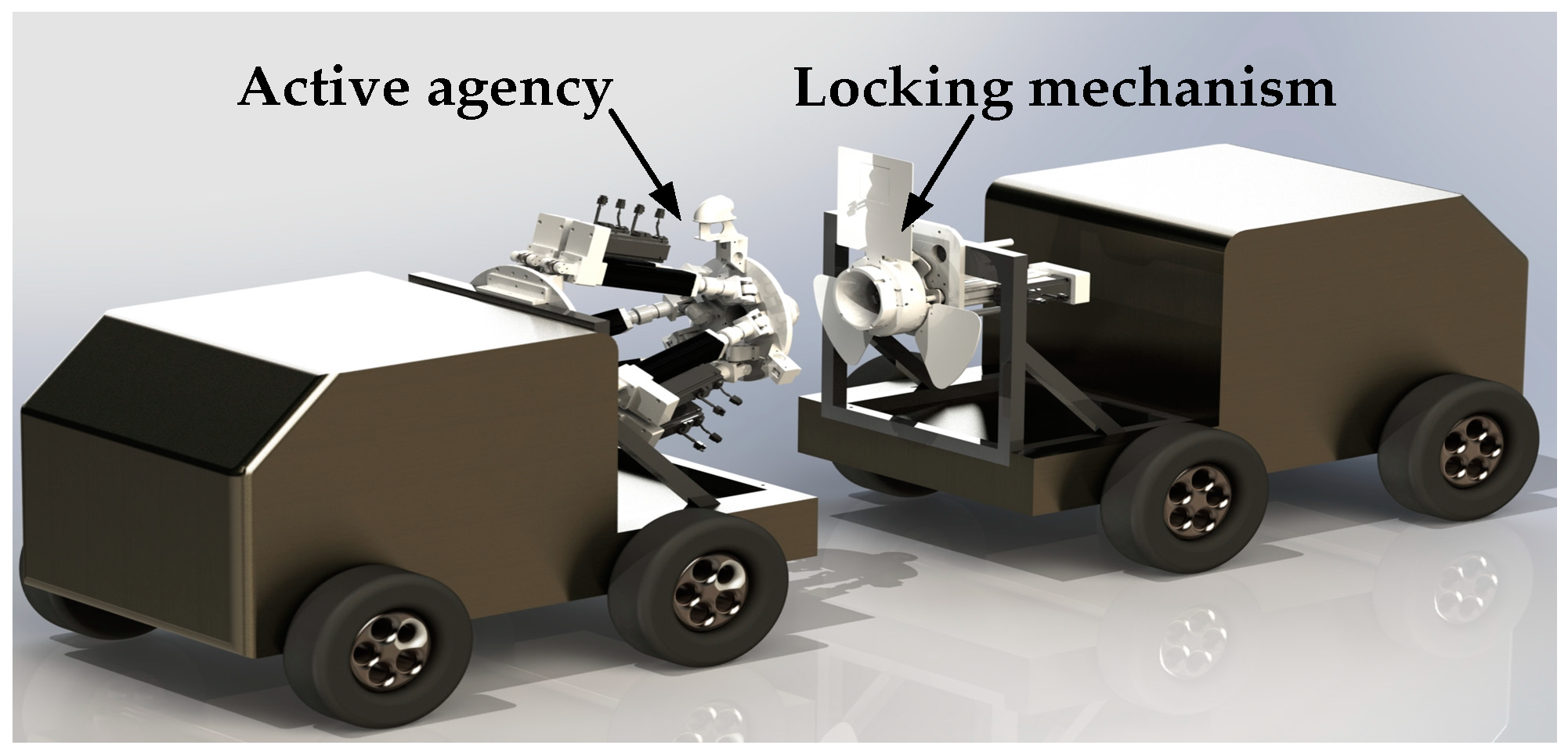
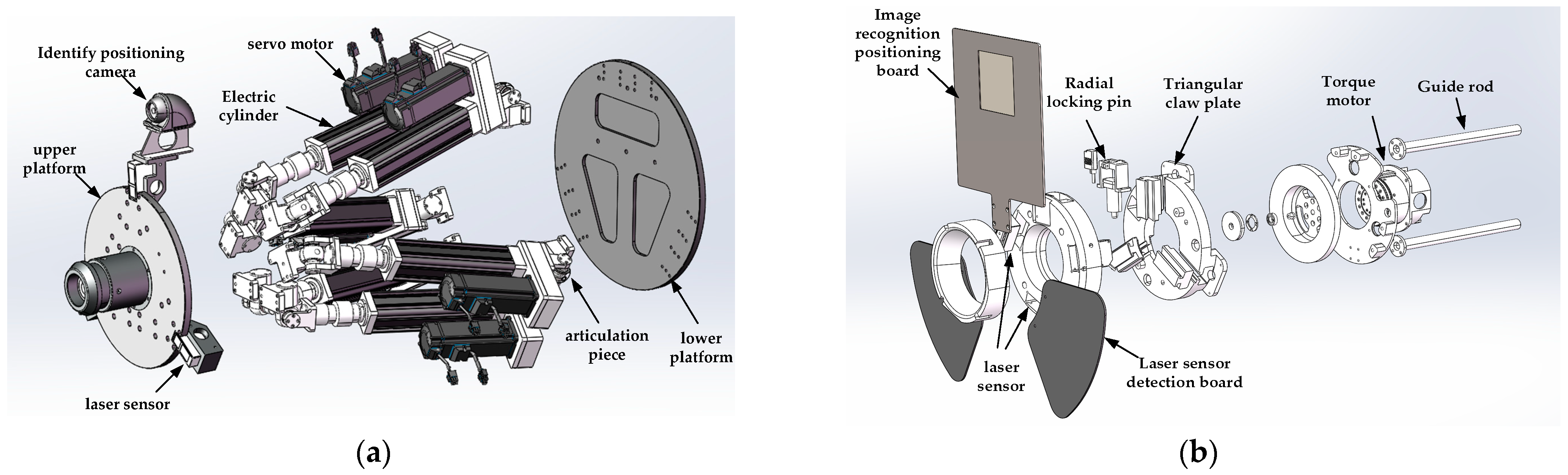
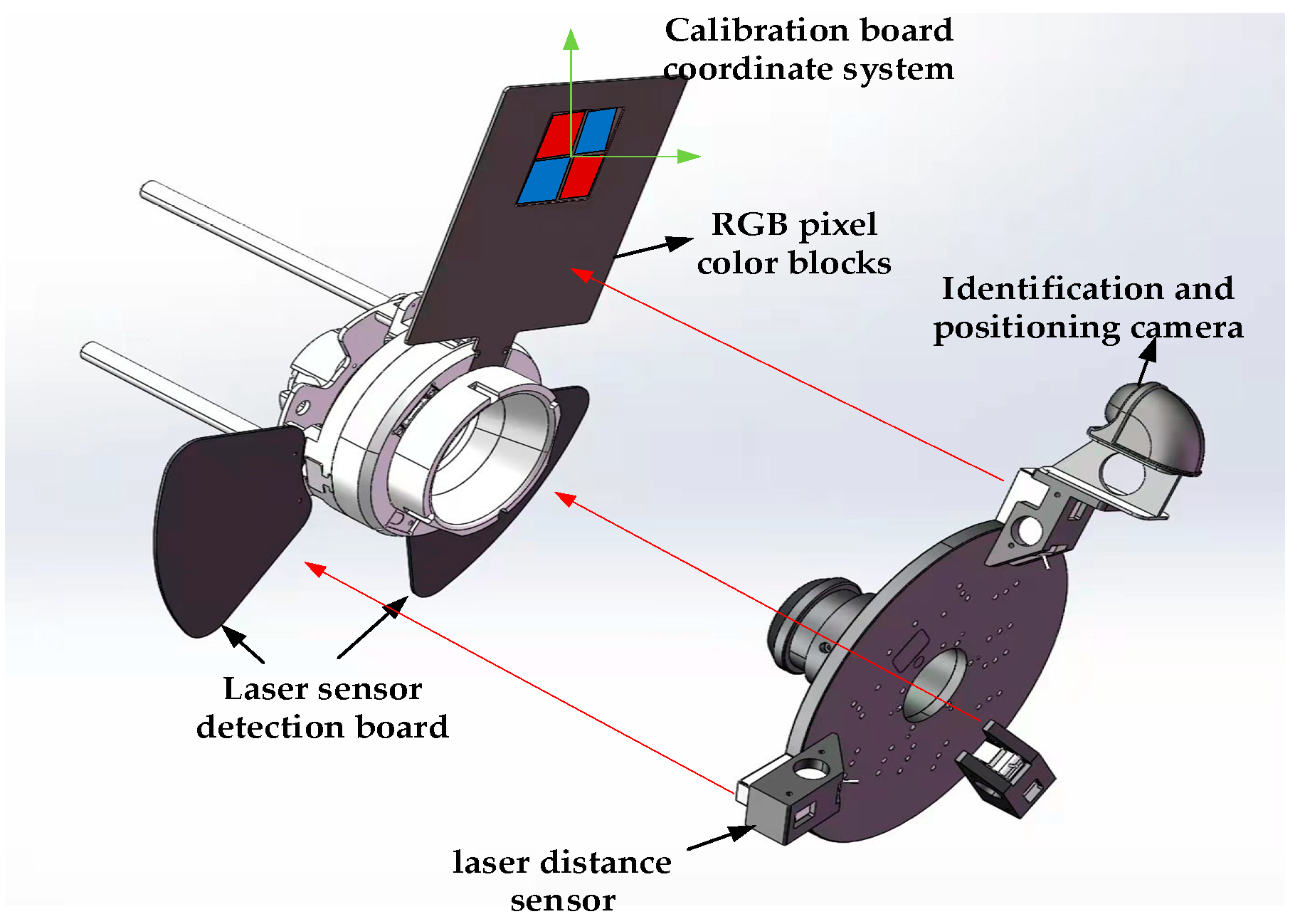
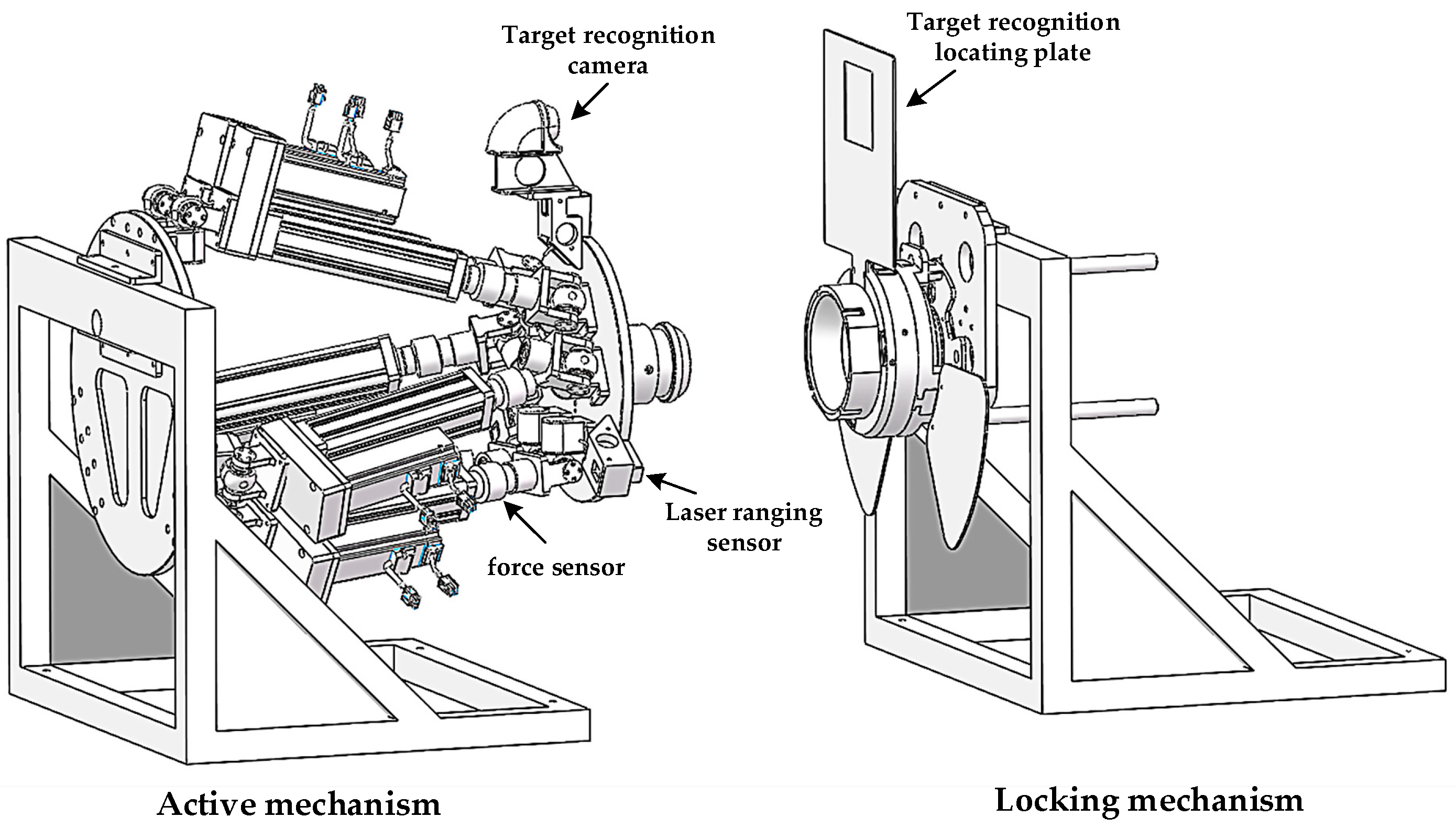
2.1. Docking Mechanism Model
2.2. Working Principle of Docking Mechanism
- (A)
- After the power is turned on, the 6-DOF platform system is initialized first, and the target recognition camera and laser ranging sensor start to work. The working space of the moving platform is w, and the locking mechanism is always in the docking area W. First, the laser ranging sensor judges whether the moving platform is in the docking area W (w∈W). If it is not, you need to adjust the two cars directly. The position is relative; if it is in the docking area, start immediately.
- (B)
- First, the controller controls the extension of the six electric cylinders to drive the active mechanism forward to the neutral position, so that the position error between the active mechanism and the locking mechanism of the six-axis platform is gradually reduced. During this period, the recognition and positioning camera and the laser ranging sensor located in the active mechanism perform target capture and real-time feedback of the pose status and transmit the information to the controller, and the six-axis platform locks the docking center for position control.
- (C)
- When it is recognized that the distance between the platform and the locking mechanism is less than a certain threshold, the locking mechanism starts to move, and the docking push rod pushes the platform forward. When the distance between the two detected by the laser ranging sensor is constant, the triangular claw is locked tightly for the first time, and the radial locking pin located in the locking mechanism is controlled by a small electric cylinder to drive the spring pin assembly to spring into the pin hole.
- (D)
- At this time, observe whether there is a change in the value of the pressure sensor. If there is any change, there is still an error in the relative position of the two mechanisms. You need to rotate the docking structure until the value of the pressure sensor is zero; now it should be successfully docked. The docking flow chart is shown in Figure 4 below.
3. Control Algorithm of Docking Mechanism Based on Image and Laser Sensor Fusion
3.1. Inverse Solution Algorithm
3.2. Multi-Sensor Information Fusion Algorithm for Image and Laser
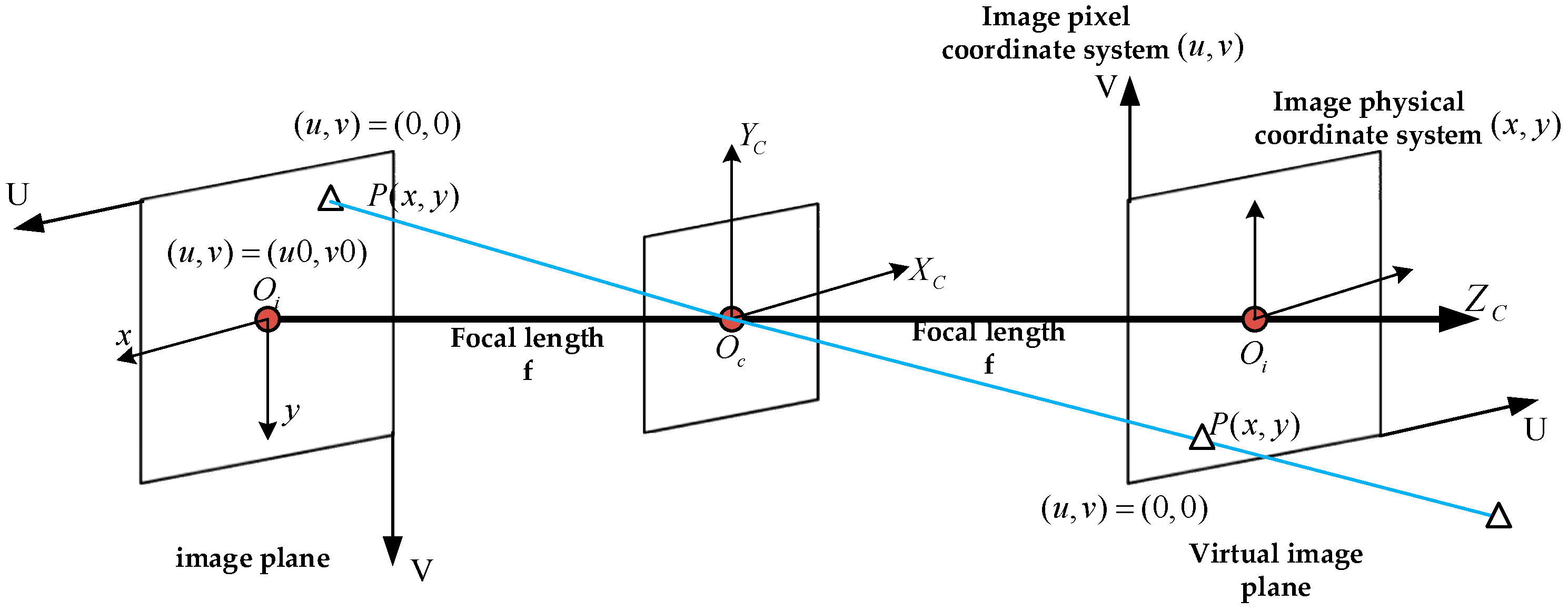
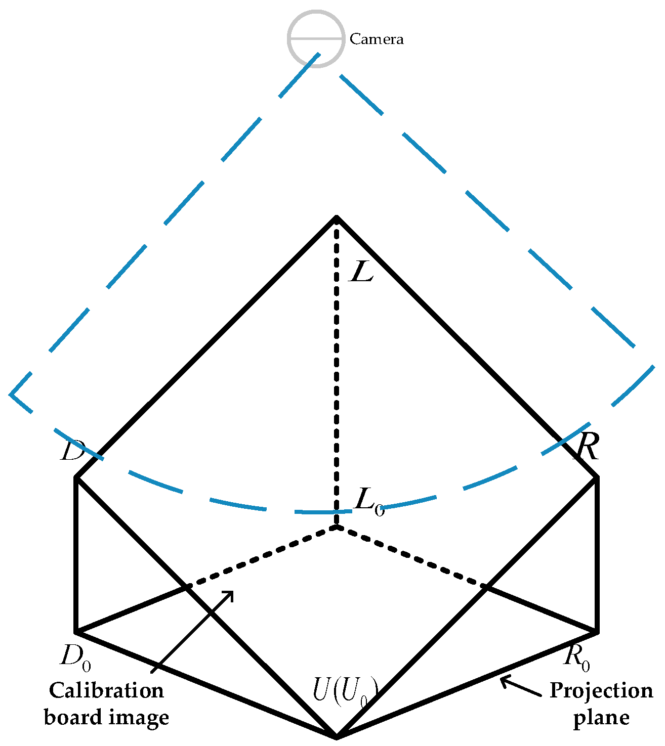
3.2.1. Image Perception Algorithm
- The calibration board is transformed from pixel coordinate system to camera coordinate system through the camera internal parameter matrix;
- The calibration board is transformed from the camera coordinate system to the world coordinate system through the camera external parameter matrix.
3.2.2. Laser Measurement Algorithm
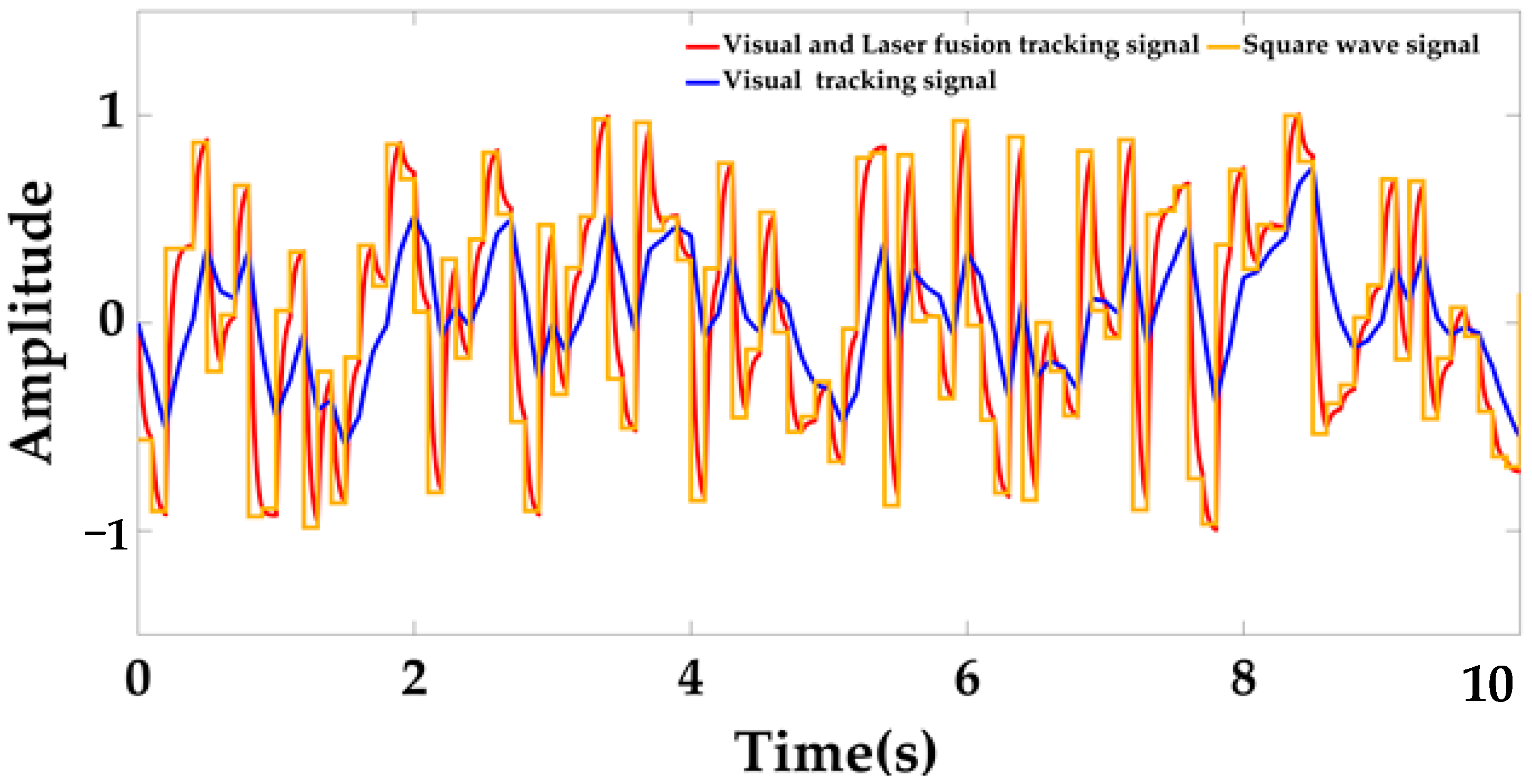
3.2.3. Fusion Algorithm of Image and Laser Sensor Information
3.3. Control Algorithm
4. Simulation and Results
4.1. Model
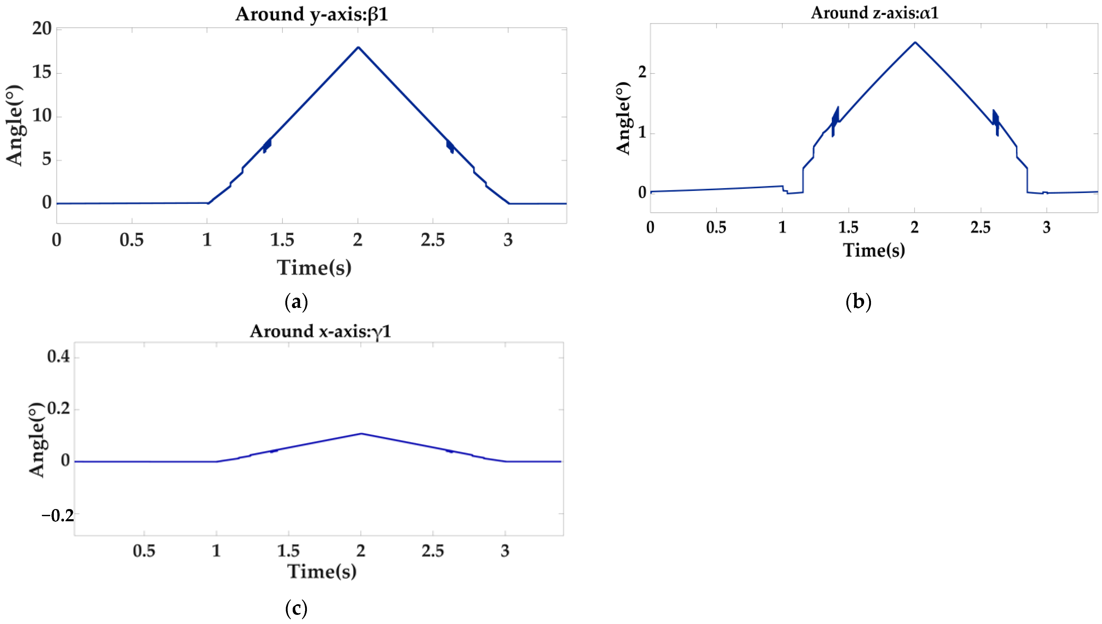
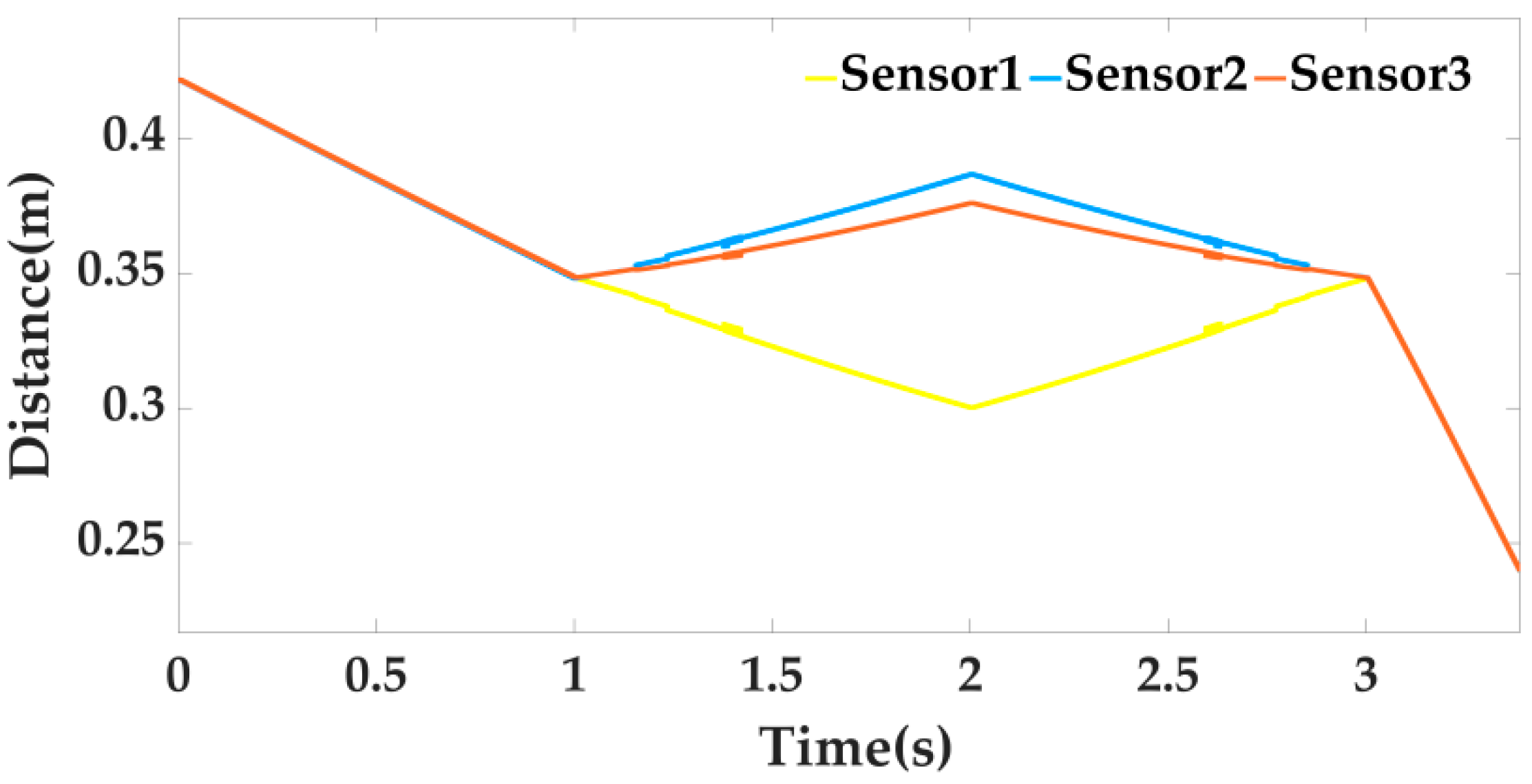
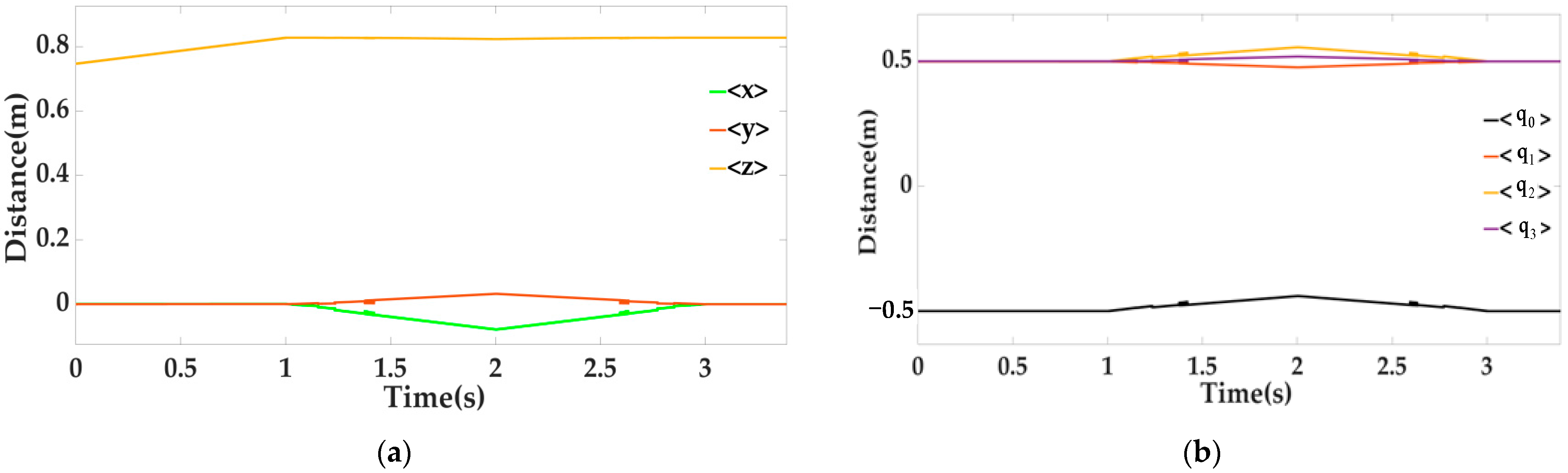
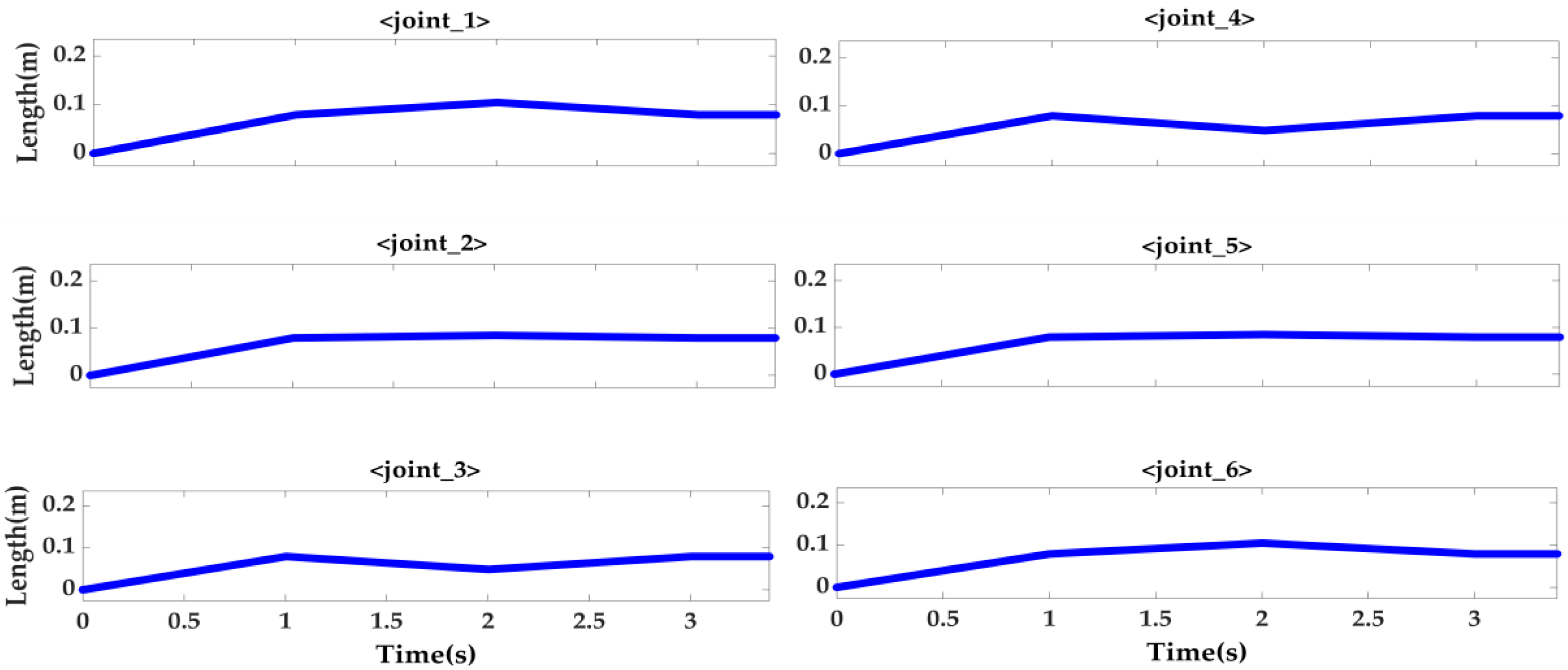
4.2. Simulation
5. Conclusions
Author Contributions
Funding
Institutional Review Board Statement
Informed Consent Statement
Conflicts of Interest
Appendix A

References
- Zhu, A. Research on Docking Technology of Ground Mobile Robot Based on Visual Navigation and Positioning. Master’s Degree Thesis, Nanjing University of Science and Technology, Nanjing, China, 2013. [Google Scholar]
- Wu, G.; Yang, Z.; Wang, W.; Guo, L.; Hu, J.; Zhou, P. On auto-docking charging control method for the inspection robot. J. Harbin Inst. Technol. 2016, 48, 123–129. [Google Scholar]
- Zheng, R.; Song, T.; Sun, Q.G.; Guo, J. Review on underwater docking technology of AUV. Chin. J. Ship Res. 2018, 13, 43–49, 65. [Google Scholar]
- Jin, C.; Li, C. ELM Neural Network Control of Attitude Management and Auxiliary Docking Maneuver after Dual-arm Space Robot Capturing Spacecraft. Robot 2017, 39, 724–732. [Google Scholar]
- Kasai, T.; Oda, M.; Suzuki, T. Results of the ETS-7 Mission-Rendezvous docking and space robotics experiments. Artif. Intell. Robot. Autom. Space 1999, 440, 299. [Google Scholar]
- Hanwen, L.; Bonan, Z.; Yu, L. Technological development of space docking agency. Spacecr. Eng. 1994, 3, 1–22. [Google Scholar]
- Theiss, B.J. A Comparison of In-flight Refueling Methods for Fighter Aircraft: Boom-receptacle vs. Probe-and-drogue. Coll. Aviat. Rev. 2007, 25, 51–72. [Google Scholar] [CrossRef]
- Zhuang, G.J.; Ge, T.; Liu, J.M. Docking navigation of the underwater self-reconfigurable system. Ocean Eng. 2011, 29, 102–107. [Google Scholar]
- Jing, F.S.; Tan, M.; Hou, Z.G.; Wang, Y.K. Posture aligning and merging system for boat blocks—Realization of coordinated manipulation with a multi-robot system. Acta Autom. Sin. 2002, 28, 708–714. [Google Scholar]
- Li, J.W.; Ge, T.; Wu, C.; Wang, X.Y. Docking Control of Underwater Self-reconfigurable Robots. J. Shanghai Jiaotong Univ. 2012, 46, 190–194, 206. [Google Scholar]
- Zhou, H.; Fan, L.; Huang, H. Design of six-degree-of-freedom automatic docking platform for large radar antenna. Electron. Mech. Eng. 2014, 30, 25–28. [Google Scholar]
- Kausar, Z.; Shah, M.; Masood, Z.; Rehman, H.; Khaydarov, S.; Saeed, M.; Razmkhah, O.; Yaqoob, H. Energy Efficient Parallel Configuration Based Six Degree of Freedom Machining Bed. Energies 2021, 14, 2642. [Google Scholar] [CrossRef]
- Xu, H.; Zhou, H.; Tan, S.; Duan, J.-A.; Hou, F. A Six-Degree-of-Freedom Compliant Parallel Platform for Optoelectronic Packaging. IEEE Trans. Ind. Electron. 2021, 68, 11178–11187. [Google Scholar] [CrossRef]
- Boissicat, W.E. A Six-Degree-of-Freedom Parallel Manipulator Using Computer Vision Targeting for Bev Charging Coupling. Bachelor’s Thesis, California State University, Sacramento, CA, USA, 2021. [Google Scholar]
- Yuan, Z.H.; Li-li, S.U.; Jian, W.A.; Xin, L.A. New Six-degree Freedom Motion Simulator and Its Performance Study. J. Harbin Univ. Sci. Technol. 2014, 19, 38–43, 48. [Google Scholar]
- Wu, L.B.; Wang, X.Y.; Li, Q. Fuzzy-immune PID control of a 6-DOF parallel platform for docking simulation. J. Zhejiang Univ. (Eng. Sci.) 2008, 42, 387–391. [Google Scholar]
- Guokun, Z.; Xiaojun, W.; Daoping, L. Study on Control Flow Based on Auto-docking System of Launch Vehicle Fuel Connector. J. Missiles Space Vehicles 2015, 1, 25–28. [Google Scholar]
- Lin, G.; Guolin, D.; Tao, Y. Performance analysis on the buffer and vibration reduction of the six-DOF parallel mechanism with the spring branched chain. J. Mach. Des. 2020, 37, 21–26. [Google Scholar]
- Stenzel, T.; Sajkowski, M.; Hetmańczyk, J.; Boratyński, T. Application of 6-DOF parallel manipulator for optoelectronic surveillance systems development. In Proceedings of the 2021 IEEE 19th International Power Electronics and Motion Control Conference (PEMC), Gliwice, Poland, 25–29 April 2021; pp. 677–681. [Google Scholar]
- Wang, S.; Chen, Z.; Li, J.; Wang, J.; Li, J.; Zhao, J. Flexible Motion Framework of the Six Wheel-legged Robot: Experimental Results. IEEE/ASME Trans. Mechatron. 2021, 1. [Google Scholar] [CrossRef]
- Chen, Z.; Wang, S.; Wang, J.; Xu, K.; Lei, T.; Zhang, H.; Wang, X.; Liu, D.; Si, J. Control strategy of stable walking for a hexapod wheel-legged robot. ISA Trans. 2021, 108, 367–380. [Google Scholar] [CrossRef]
- Chen, Z.; Wang, S.; Wang, J.; Xu, K. Attitude stability Control for Multi-Agent Six Wheel-Legged Robot. IFAC-Pap. 2020, 53, 9636–9641. [Google Scholar] [CrossRef]
- Chen, Z.; Li, J.; Wang, J.; Wang, S.; Zhao, J.; Li, J. Towards Hybrid Gait Obstacle Avoidance for a Six Wheel-Legged Robot with Payload Transportation. J. Intell. Robot. Syst. 2021, 102, 1–21. [Google Scholar] [CrossRef]
- Li, J.; Qin, H.; Wang, J.; Li, J. OpenStreetMap-Based Autonomous Navigation for the Four Wheel-Legged Robot Via 3D-Lidar and CCD Camera. IEEE Trans. Ind. Electron. 2021, 69, 2708–2717. [Google Scholar] [CrossRef]
- Li, J.; Wang, J.; Peng, H.; Hu, Y.; Su, H. Fuzzy-Torque Approximation-Enhanced Sliding Mode Control for Lateral Stability of Mobile Robot. IEEE Trans. Syst. Man Cybern. Syst. 2021, 1–10. [Google Scholar] [CrossRef]
- Velasco, J.; Calvo, I.; Barambones, O.; Venegas, P.; Napole, C. Experimental Validation of a Sliding Mode Control for a Stewart Platform Used in Aerospace Inspection Applications. Mathematics 2020, 8, 2051. [Google Scholar] [CrossRef]
- Khusro, Y.R.; Zheng, Y.; Grottoli, M.; Shyrokau, B. MPC-Based Motion-Cueing Algorithm for a 6-DOF Driving Simulator with Actuator Constraints. Vehicles 2020, 2, 625–647. [Google Scholar] [CrossRef]
- Copot, C.; Muresan, C.; Beschi, M.; Ionescu, C. A 6DOF Virtual Environment Space Docking Operation with Human Supervision. Appl. Sci. 2021, 11, 3658. [Google Scholar] [CrossRef]
- Yun, S.M.; Kim, S.P.; Chung, S.M.; Shin, W.J.; Cho, D.S.; Park, J.C. Structural Safety Assessment of Connection between Sloshing Tank and 6-DOF Platform Using Co-Simulation of Fluid and Multi-Flexible-Body Dynamics. Water 2020, 12, 2108. [Google Scholar] [CrossRef]
- Abdelaal, A.E.; Hong, N.; Avinash, A.; Budihal, D.; Sakr, M.; Hager, G.D.; Salcudean, S.E. Orientation Matters: 6-DoF Autonomous Camera Movement for Minimally Invasive Surgery. arXiv 2020, arXiv:2012.02836. [Google Scholar]
- Zhang, Z.; Zhang, X.; Bian, X. Research and optimization of special vehical seamless docking system. Automob. Appl. Technol. 2020, 10, 102–105. [Google Scholar]
- de Jesús Rubio, J.; Lughofer, E.; Pieper, J.; Cruz, P.; Martinez, D.I.; Ochoa, G.; Islas, M.A.; Garcia, E. Adapting H-infinity controller for the desired reference tracking of the sphere position in the maglev process. Inf. Sci. 2021, 569, 669–686. [Google Scholar] [CrossRef]
- Aguilar-Ibanez, C.; Moreno-Valenzuela, J.; García-Alarcón, O.; Martinez-Lopez, M.; Acosta, J.Á.; Suarez-Castanon, M.S. PI-Type Controllers and Σ–Δ Modulation for Saturated DC-DC Buck Power Converters. IEEE Access 2021, 9, 20346–20357. [Google Scholar] [CrossRef]
- Martinez, D.I.; Rubio, J.D.; Aguilar, A.; Pacheco, J.; Gutierrez, G.J.; Garcia, V.; Vargas, T.M.; Ochoa, G.; Cruz, D.R.; Juarez, C.F. Stabilization of Two Electricity Generators. Complexity 2020, 2020, 8683521. [Google Scholar] [CrossRef]
- Soriano, L.A.; Zamora, E.; Vazquez-Nicolas, J.M.; Hernández, G.; Madrigal, J.A.; Balderas, D. PD Control Compensation Based on a Cascade Neural Network Applied to a Robot Manipulator. Front. Neurorobot. 2020, 14, 577749. [Google Scholar] [CrossRef] [PubMed]
- Silva-Ortigoza, R.; Hernández-Márquez, E.; Roldán-Caballero, A.; Tavera-Mosqueda, S.; Marciano-Melchor, M.; García-Sánchez, J.R.; Hernández-Guzmán, V.M.; Silva-Ortigoza, G. Sensorless Tracking Control for a “Full-Bridge Buck Inverter–DC Motor” System: Passivity and Flatness-Based Design. IEEE Access 2021, 9, 132191–132204. [Google Scholar] [CrossRef]
- Khan, J.; Khan, M.U.G.; Iqbal, R.; Riaz, O. Robust Multisensor Fusion for the Development of EEG Controlled Vehicle. IEEE Sens. J. 2021, 21, 15635–15642. [Google Scholar] [CrossRef]
- Akshaya, T.G.; Sreeja, S. Multi-sensor Data Fusion for Aerodynamically Controlled Vehicle Based on FGPM. IFAC-Pap. 2020, 53, 591–596. [Google Scholar] [CrossRef]
- Yang, Y.; Huang, Y.; Yang, H.; Zhang, T.; Wang, Z.; Liu, X. Real-Time Terrain-Following of an Autonomous Quadrotor by Multi-Sensor Fusion and Control. Appl. Sci. 2021, 11, 1065. [Google Scholar] [CrossRef]
- Yazdkhasti, S.; Sasiadek, J.Z. Multi sensor fusion based on adaptive kalman filtering. In Advances in Aerospace Guidance, Navigation and Control; Springer: Cham, Switzerland, 2018; pp. 317–333. [Google Scholar]


| Description | Value |
|---|---|
| Up and down calibration range of electric Median length of electric cylinder | 464–614 mm 539 mm |
| Moving platform radius | 127.5 mm |
| Static platform radius | 162.5 mm |
| Description | Model/Value |
|---|---|
| The controller | Beckhoff |
| Communication protocol of the terminal module | EtherCAT |
| Laser ranging sensor | 200–1000 mm |
| The torque motor | 42–80 Nm |
| Laser locking sensor | ±80 mm |
Publisher’s Note: MDPI stays neutral with regard to jurisdictional claims in published maps and institutional affiliations. |
© 2022 by the authors. Licensee MDPI, Basel, Switzerland. This article is an open access article distributed under the terms and conditions of the Creative Commons Attribution (CC BY) license (https://creativecommons.org/licenses/by/4.0/).
Share and Cite
Zhan, G.; Niu, S.; Zhang, W.; Zhou, X.; Pang, J.; Li, Y.; Zhan, J. A Docking Mechanism Based on a Stewart Platform and Its Tracking Control Based on Information Fusion Algorithm. Sensors 2022, 22, 770. https://doi.org/10.3390/s22030770
Zhan G, Niu S, Zhang W, Zhou X, Pang J, Li Y, Zhan J. A Docking Mechanism Based on a Stewart Platform and Its Tracking Control Based on Information Fusion Algorithm. Sensors. 2022; 22(3):770. https://doi.org/10.3390/s22030770
Chicago/Turabian StyleZhan, Gan, Shaohua Niu, Wencai Zhang, Xiaoyan Zhou, Jinhui Pang, Yingchao Li, and Jigang Zhan. 2022. "A Docking Mechanism Based on a Stewart Platform and Its Tracking Control Based on Information Fusion Algorithm" Sensors 22, no. 3: 770. https://doi.org/10.3390/s22030770
APA StyleZhan, G., Niu, S., Zhang, W., Zhou, X., Pang, J., Li, Y., & Zhan, J. (2022). A Docking Mechanism Based on a Stewart Platform and Its Tracking Control Based on Information Fusion Algorithm. Sensors, 22(3), 770. https://doi.org/10.3390/s22030770