


Simulation-Based Approach to the Matching of a Dielectric-Filled Circular Waveguide Aperture


Abstract
:1. Introduction
2. New Innovative Aperture-Matching Method
3. Conclusions
Author Contributions
Funding
Institutional Review Board Statement
Informed Consent Statement
Data Availability Statement
Conflicts of Interest
References
- Amitay, N.; Galindo, V. The analysis of circular waveguide phased arrays. Bell Sys. Tech. J. 1968, 47, 1903–1932. [Google Scholar] [CrossRef]
- Li, Z.; Li, X.; Wan, C. Design of a Ka-band slant polarized circular waveguide phased array antenna. In Proceedings of the 9th Asia-Pacific Conference on Antennas and Propagation (APCAP), Xiamen, China, 4–7 August 2020. [Google Scholar]
- Gu, C.; Cheng, F.; Zhang, Z. Design of a compact D-band all-metal antenna fed by a circular waveguide. In Proceedings of the IEEE MTT-S International Microwave Workshop Series on Advanced Materials and Processes for RF and THz Applications (IMWS-AMP), Chongqing, China, 15–17 November 2021. [Google Scholar]
- Qudrat-E-Maula, M.; Shafai, L.; Pour, Z.A. Dielectric loaded circular waveguide feeds. In Proceedings of the 16th International Symposium on Antenna Technology and Applied Electromagnetics (ANTEM), Victoria, BC, Canada, 13–16 July 2014. [Google Scholar]
- Kehn, M.N.M.; Kildal, P.S.; Skobelev, S.P. Miniaturized dielectric-loaded rectangular waveguides for use in multi-frequency arrays. In Proceedings of the IEEE Antennas and Propagation Society International Symposium, Monterey, CA, USA, 20–25 June 2004. [Google Scholar]
- Liang, X.; Zhang, Z.; Zeng, J.; Guan, F.; Liu, X.; Zi, J. Scan blindness free design of wideband wide-scanning open-ended waveguide phased array. IEEE Access 2021, 9, 68127–68138. [Google Scholar] [CrossRef]
- Sporer, M.; Weigel, R.; Koelpin, A. Open-ended dielectric-filled waveguide antenna for underwater usage. In Proceedings of the 44th European Microwave Conference, Rome, Italy, 6–9 October 2014. [Google Scholar]
- Xu, D.; Li, Z.; Chen, X.; Wang, Z.; Wu, J. A dielectric-filled waveguide antenna element for 3D imaging radar in high temperature and excessive dust conditions. Sensors 2016, 16, 1339. [Google Scholar] [CrossRef] [PubMed]
- Chaudhury, D.N. An Investigation on the Possibility for Bandwidth Improvement of Dielectric Antennas via Modification of Their Geometry. Master’s Thesis, KTH Royal Institute of Technology, Stokholm, Sweden, 2020. [Google Scholar]
- C-Lec Plastics Inc. Available online: https://rexolite.com/rexolite/ (accessed on 7 October 2023).
- Riddle, B.; Baker-Jarvis, J.; Krupka, J. Complex permittivity measurements of common plastics over variable temperatures. IEEE Trans. Microw. Theory Tech. 2003, 51, 727–733. [Google Scholar] [CrossRef]
- Laird Technologies Inc. Eccostock® LoK. Available online: https://www.laird.com/products/microwave-absorbers/low-loss-dielectrics/eccostock-lok (accessed on 7 October 2023).
- Laird Technologies Inc. Eccostock® HIK500F. Available online: https://www.laird.com/sites/default/files/2021-01/RFP-DS-HIK500F.pdf (accessed on 7 October 2023).
- Laird Technologies Inc. Eccostock®.0005. Available online: https://www.laird.com/sites/default/files/2021-01/RFP-DS-0005%20112515.pdf (accessed on 1 November 2023).
- Cuming Microwave Corp. C-STOCK®.0005. Available online: https://www.cumingmicrowave.com/pdf/210-Dielectrics/210-3%20C-STOCK%20.0005.pdf (accessed on 1 November 2023).
- Laird Technologies Inc. Eccostock® HIK. Available online: https://www.laird.com/sites/default/files/2021-01/DS%20ECCOSTOCK%20HiK.pdf (accessed on 1 November 2023).
- Cuming Microwave Corp. C-STOCK® AK. Available online: https://www.cumingmicrowave.com/pdf/210-Dielectrics/210-1%20C-STOCK%20AK%20&%20AK-500.pdf (accessed on 1 November 2023).
- National Magnetics Group Inc. Microwave Dielectric Materials. Available online: https://www.magneticsgroup.com/material/k/ (accessed on 1 November 2023).
- Avient Corp. PREPERM® Series. Available online: https://www.avient.com/sites/default/files/2021-12/PREPERM%20_%20Edgetek%20Low-loss%20Dielectric%20Thermoplastics%20Technical%20Bulletin.pdf (accessed on 1 November 2023).
- Avient Corp. EDGETEK® 7500 Series. Available online: https://www.avient.com/sites/default/files/2021-12/Edgetek%20High%20Impact%20PKE%20Technical%20Bulletin.pdf (accessed on 1 November 2023).
- Wheeler, H.A. A systematic approach to the design of a radiator element for a phased-array antenna. Proc. IEEE 1968, 56, 1940–1951. [Google Scholar] [CrossRef]
- Lee, J.J.; Chu, R.-S. Aperture matching of a dielectric loaded circular waveguide element array. IEEE Trans. Antennas Propag. 1989, 37, 395–399. [Google Scholar] [CrossRef]
- Boyd, C.R. Impedance matching of open-ended waveguide radiating elements. In Proceedings of the SBMO International Microwave Symposium, Rio de Janeiro, Brazil, 27–30 July 1987. [Google Scholar]
- Lewis, L.; Kaplan, L.; Hanfling, J. Synthesis of a waveguide phased array element. IEEE Trans. Antennas Propag. 1974, 22, 536–540. [Google Scholar] [CrossRef]
- Chan, K.K.; Martin, R.; Chadwick, K. A broadband end launched coaxial-to-waveguide transition for waveguide phased arrays. In Proceedings of the IEEE AP-S International Symposium, Atlanta, GA, USA, 21−26 June 1998. [Google Scholar]
- Durga, M.; Tomar, S.; Singh, S.; Suthar, L. Millimeter wave in-line coaxial-to-rectangular waveguide transition. In Proceedings of the IEEE Applied Electromagnetics Conference, Kolkata, India, 18−22 December 2011. [Google Scholar]
- Simone, M.; Fanti, A.; Lodi, M.-B.; Pisanu, T.; Mazzarella, G. An in-line coaxial-to-waveguide transition for Q-band single-feed-per-beam antenna systems. Appl. Sci. 2021, 11, 2524. [Google Scholar] [CrossRef]
- Mohamadzade, B.; Dunning, A.; Hayman, D.B.; Smart, K. Broadband coaxial-to-rectangular waveguide transition. In Proceedings of the International Conference on Electromagnetics in Advanced Applications (ICEAA), Venice, Italy, 9−13 October 2023. [Google Scholar]
- Kehn, M.N.M.; Kildal, P.S. Miniaturized rectangular hard waveguides for use in multifrequency phased arrays. IEEE Trans. Antennas Propag. 2005, 53, 100–109. [Google Scholar] [CrossRef]
- Bai, Y.; Wang, L.; Zhang, L.; Wang, P.; Peng, B. 16-channel wavelength division multiplexers based on subwavelength grating. Appl. Sci. 2023, 13, 1833. [Google Scholar] [CrossRef]
- Simoncini, G.; Rossi, R.; Alimenti, F.; Vincenti Gatti, R. Single-ridge waveguide compact and wideband hybrid couplers for X/Ku-band applications. Electronics 2022, 11, 1538. [Google Scholar] [CrossRef]
- Bermúdez-Martín, D.; Gillard, R.; Molero, C.; Legay, H.; García-Vigueras, M. Methodology for improving scanning performance loading an array element with a 3D all-metal WAIM. Electronics 2022, 11, 2848. [Google Scholar] [CrossRef]
- Ahmed, F.; Hayat, T.; Afzal, M.U.; Zhang, S.; Esselle, K.P.; Whittow, W. 3D printable synthetic metasurface to realize 2D beam-steering antenna. IEEE Open J. Antennas Propag. 2023, 4, 506–519. [Google Scholar] [CrossRef]
- Heo, J.-W.; Xu, S.; Atlanzaya, E.; Zhang, Q.; Lee, C.-S.; Ahn, B.-C.; Ahn, J.-H.; Choi, S.-G. A new technique for broadband matching of open-ended rectangular waveguide radiator. Sensors 2023, 23, 9176. [Google Scholar] [CrossRef] [PubMed]
- Herhil, Y.; Piltyay, S.; Blashenko, A. Characteristic impedance of rectangular and circular waveguides for fundamental modes. In Proceedings of the 2021 IEEE 3rd Ukraine Conference on Electrical and Computer Engineering (UKRCON), Lviv, Ukraine, 26–28 August 2021. [Google Scholar]
- Bang, J.-H.; Ahn, B.-C. Coaxial-to-circular waveguide transition with broadband mode-free operation. Electron. Lett. 2014, 50, 1453–1454. [Google Scholar] [CrossRef]


| Typical Properties | Eccostock® LoK | Typical Properties | Eccostock® HIK500F | |
|---|---|---|---|---|
| Temperature Range, °C (°F) | −70 to 150 (−94 to 302) | Temperature Range, °C (°F) | −56 to 204 (−69 to 400) | |
| Frequency | 60 Hz to 10 GHz | Density, g/cc | 2.2 | |
| Density, g/cc | 0.54 | Dielectric Strength, Volts/mil | >300 | |
| Dielectric Constant | 1.7 | Dielec, Const. Accuracy, K < 16 (K > 16) | ±3% (±10%) | |
| Dielectric Strength, Volts/mil (kV/mm) | 300 (11.8) | Dissipation Factor, 1 to 10 GHz | <0.002 | |
| Dissipation Factor | <0.004 | Volume Resistivity, ohm-cm | >1014 | |
| Volume Resistivity, ohm-cm | 1014 | Flexural Strength, kg/cm2 (psi) | 703 (10000) | |
| Flexural Strength, kg/cm2 (psi) | 420 (6000) | Coefficient of Linear Expansion, /°C | 36 × 10−6 | |
| Coeff. of Linear Expansion, per °C (°F) | 50 × 10−6 (28 × 10−6) | Izod Imp., kg-cm/cm (ft-lb/in) | 1.65 (0.3) | |
| Thermal Conductivity, W/mK | 0.4 | Outgassing, %TML (%CVCM) | 0.47 (0.041) | |
| Water absorption, %gain in 24 h at 25 °C | 0.1 |
| Manufacturer | Product Name | Frequency (GHz) | Dielectric Constant | Loss Tangent Range |
|---|---|---|---|---|
| C-Lec Plastics [10] | Rexolite® 1422 | 10 | 2.53 | 0.00066 |
| Laird Technologies [12] | Eccostock® LoK | 10 | 1.7 | <0.004 |
| Laird Technologies [13] | Eccostock® HIK500F | 10 | 3, 4, 5, 6, 7, 8, 9, 10, 11, 12, 16, 20, 25, 30 | <0.002 |
| Laird Technologies [14] | Eccostock® 0005 | 500 | 2.53 | 0.0005 |
| Cuming Microwave [15] | C-STOCK® 0005 | - | 2.54 | 0.0005 |
| Laird Technologies [16] | Eccostock® HIK | 10 | 3, 3.5, 3.8, 4, 4.5, 5, 6, 7, 8, 9, 10, 11, 12, 13, 14, 15 | <0.002 |
| Cuming Microwave [17] | C-STOCK® AK | - | 3, 4, 5, 6, 7, 8, 9, 10, 12, 15, 20 | <0.002 |
| National Magnetics Group [18] | Microwave Dielectric Materials | 9.4 | 4.3, 6.3, 9, 9.5, 12, 15, 16, 18, 20, 20, 25, 30, 50, 80, 100, 140, 160, 250 | 0.0002–0.005 |
| Avient [19] | PREPERM® Series | 2.4 | 2.6, 2.7, 3.0, 3.2, 3.5, 4.0, 4.4, 5.0, 6.5, 8.0, 9.5, 10.0, 11.0, 12.0, 15.0, 23.0 | 0.0009–0.0045 |
| Avient [20] | EDGETEK® 7500 Series | 1 | 3.0, 3.3, 3.4, 3.6, 3.8, 4.4, 4.8, 5.3, 5.9, 6.0, 7.0, 7.3, 9.0 | 0.0002–0.0012 |
| Matching Structure | Waveguide Diameter (mm) | εr | fcTE11 (GHz) | fcTM11 (GHz) | fcTE12 (GHz) | fcTM12 (GHz) |
|---|---|---|---|---|---|---|
| 0 | 9.20 | 1.0 | 19.10 | 39.74 | 55.30 | 72.77 |
| 1 | 9.20 | 1.8 | 14.23 | 29.62 | 41.22 | 54.24 |
| 2 | 9.20 | 2.5 | 12.08 | 25.14 | 34.98 | 46.02 |
| 3 | 9.20 | 5.0 | 8.54 | 17.77 | 24.73 | 32.54 |
| 4 | 9.20 | 7.5 | 6.97 | 14.51 | 20.19 | 26.57 |
| 5 | 9.20 | 10.0 | 6.04 | 12.56 | 17.49 | 23.01 |
| Matching Structure | εr | D0 | D1 | D2 | D3 | L0 | L1 | L2 | L3 | S | 2a | t |
|---|---|---|---|---|---|---|---|---|---|---|---|---|
| 1 | 1.8 | 10.80 | 0 | 5.35 | 1.10 | 0 | 1.80 | 2.60 | 20.00 | 0 | 9.20 | 0.80 |
| 2 | 2.5 | 10.80 | 0 | 5.50 | 1.00 | 0 | 2.10 | 3.00 | 20.00 | 0 | 9.20 | 0.80 |
| 3 | 5.0 | 10.80 | 0 | 6.00 | 1.70 | 0 | 2.80 | 4.06 | 20.00 | 0 | 9.20 | 0.80 |
| 4 | 7.5 | 10.80 | 0 | 5.50 | 2.00 | 0 | 3.00 | 3.50 | 20.00 | 0 | 9.20 | 0.80 |
| 5 | 10.0 | 10.80 | 0 | 7.19 | 2.46 | 0 | 3.37 | 4.94 | 20.00 | 0 | 9.20 | 0.80 |
| Matching Structure | εr | D0 | D1 | D2 | D3 | L0 | L1 | L2 | L3 | S | 2a | t |
|---|---|---|---|---|---|---|---|---|---|---|---|---|
| 1 | 1.8 | 9.80 | 9.97 | 4.73 | 0.94 | 1.05 | 1.97 | 1.70 | 20.00 | 0.27 | 9.20 | 0.80 |
| 2 | 2.5 | 9.80 | 10.28 | 4.74 | 0.52 | 0.89 | 1.88 | 1.73 | 20.00 | 0.24 | 9.20 | 0.80 |
| 3 | 5.0 | 9.80 | 7.48 | 4.31 | 1.38 | 1.51 | 2.19 | 2.89 | 20.00 | 0.49 | 9.20 | 0.80 |
| 4 | 7.5 | 9.80 | 8.90 | 4.47 | 1.20 | 0.79 | 3.36 | 2.93 | 20.00 | 0.58 | 9.20 | 0.80 |
| 5 | 10.0 | 9.80 | 9.29 | 5.26 | 1.39 | 5.01 | 3.21 | 4.22 | 20.00 | 0.21 | 9.20 | 0.80 |
| Matching Structure | εr | Frequency Range (GHz) | Matched Reflection Coefficient (dB) | Unmatched Reflection Coefficient (dB) |
|---|---|---|---|---|
| 1 | 1.8 | 16.8–29.5 | −40.1 to −27.0 | −16.3 to −15.4 |
| 2 | 2.5 | 13.1–25.3 | −46.3 to −25.3 | −11.4 to −9.5 |
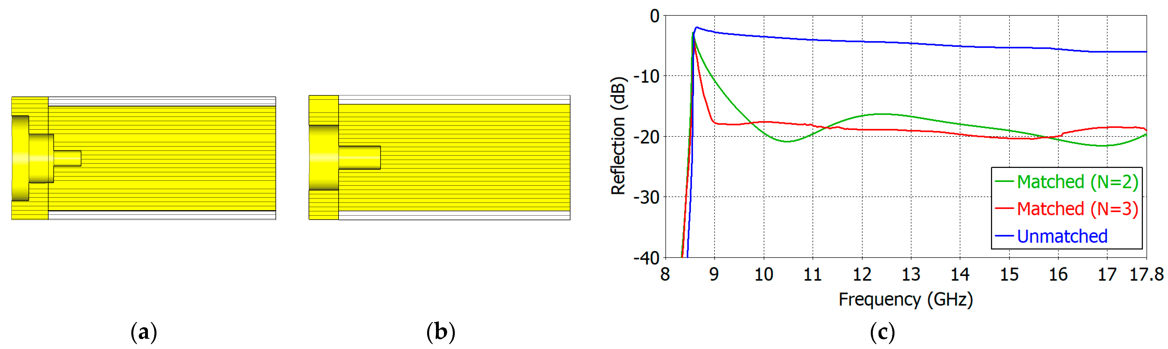
| 3 | 5.0 | 9.6–17.8 | −20.86 to −16.3 | −6.0 to −3.3 |
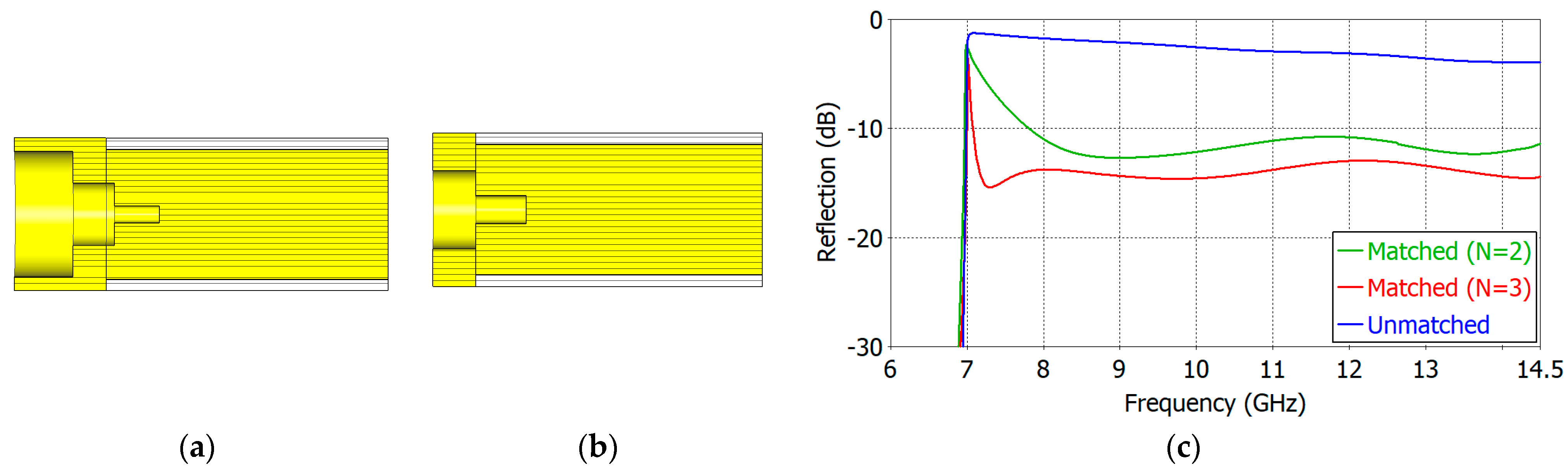
| 4 | 7.5 | 7.9–14.5 | −12.7 to −10.8 | −4.0 to −1.7 |
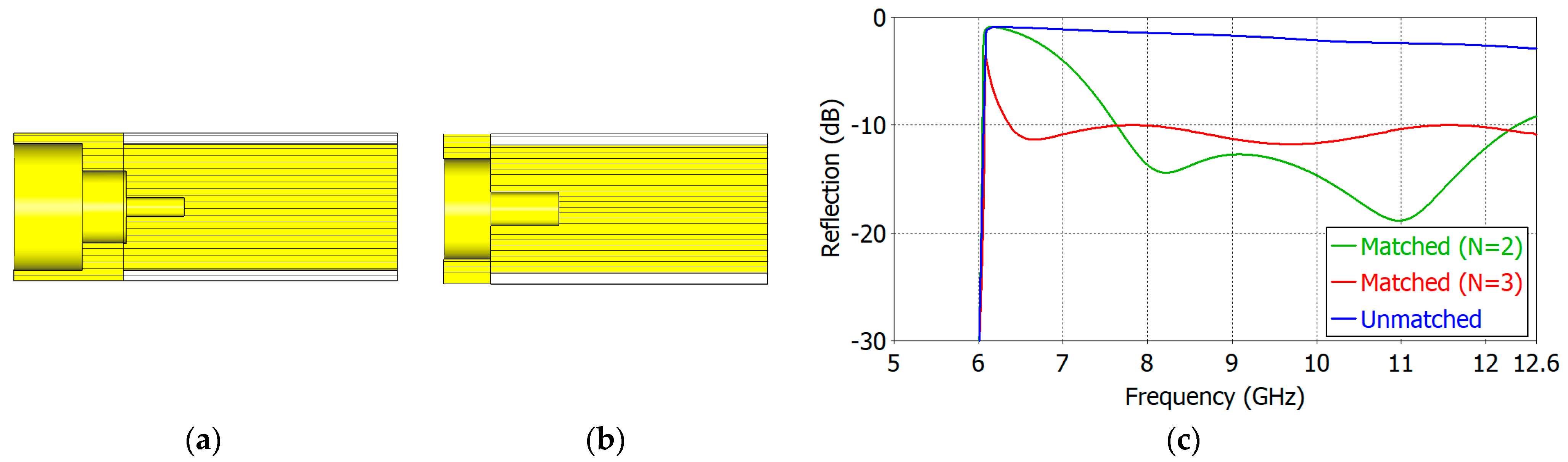
| 5 | 10.0 | 7.6–12.4 | −18.8 to −10.0 | −2.8 to −1.4 |
| Matching Structure | εr | Frequency Range (GHz) | Matched Reflection Coefficient (dB) | Unmatched Reflection Coefficient (dB) |
|---|---|---|---|---|
| 1 | 1.8 | 17.2–29.5 | −37.9 to −30.6 | −16.3 to −15.4 |
| 2 | 2.5 | 12.9–25.3 | −50.0 to −20.5 | −11.4 to −9.2 |
| 3 | 5.0 | 9.0–17.8 | −20.4 to −17.6 | −6.0 to −2.8 |
| 4 | 7.5 | 7.1–14.5 | −15.4 to −12.9 | −1.3 to −4.0 |
| 5 | 10.0 | 6.4–12.6 | −11.8 to −10.0 | −2.9 to −0.9 |
| Matching Structure | εr | Length LA Outside the Waveguide (mm) | LA/(2a) | Length LB Inside the Waveguide (mm) | LB/(2a) | (LA + LB)/(2a) |
|---|---|---|---|---|---|---|
| 1 | 1.8 | 1.80 | 0.20 | 2.60 | 0.28 | 0.48 |
| 2 | 2.5 | 2.10 | 0.23 | 3.00 | 0.33 | 0.56 |
| 3 | 5.0 | 2.56 | 0.28 | 3.60 | 0.39 | 0.67 |
| 4 | 7.5 | 3.00 | 0.33 | 3.50 | 0.38 | 0.71 |
| 5 | 10.0 | 3.37 | 0.37 | 4.94 | 0.54 | 0.91 |
| Matching Structure | εr | Length LA Outside the Waveguide (mm) | LA/(2a) | Length LB Inside the Waveguide (mm) | LB/(2a) | (LA + LB)/(2a) |
|---|---|---|---|---|---|---|
| 1 | 1.8 | 2.76 | 0.30 | 1.71 | 0.19 | 0.49 |
| 2 | 2.5 | 2.60 | 0.28 | 3.03 | 0.33 | 0.61 |
| 3 | 5.0 | 3.21 | 0.35 | 2.89 | 0.31 | 0.66 |
| 4 | 7.5 | 6.50 | 0.71 | 3.79 | 0.41 | 1.12 |
| 5 | 10.0 | 8.01 | 0.87 | 4.43 | 0.48 | 1.35 |
| Matching Structure | εr | TE11−Mode Cutoff (fcTE11) (GHz) | Start Frequency (fS) for |S11| < −10 dB (GHz) | fS/fcTE11 | |S11| at fS in Unmatched Case (dB) | Plateau Value of |S11| (dB) | Frequency Range (fa−fb) for Plateau |S11| (GHz) |
|---|---|---|---|---|---|---|---|
| 1 | 1.8 | 14.23 | 14.83 | 1.042 | −10.7 | −31.7 | 17.5–29.4 |
| 2 | 2.5 | 12.08 | 12.32 | 1.020 | −6.44 | −20.5 | 12.9–25.3 |
| 3 | 5.0 | 8.54 | 8.67 | 1.015 | −2.11 | −18.8 | 8.9–17.8 |
| 4 | 7.5 | 6.97 | 7.09 | 1.017 | −1.27 | −13.1 | 7.2–14.5 |
| 5 | 10.0 | 6.04 | 6.35 | 1.051 | −0.93 | −10.0 | 6.4–12.6 |
| Matching Structure | εr | Wavelength in Vacuum λ0 (mm) at fa | Waveguide Dia. In Wavelength (2a/λ0) | Gain (dBi) at fa | Gain (dBi) at Middle Freq. fm | Gain (dBi) at End Freq. fb |
|---|---|---|---|---|---|---|
| 0 | 1.0 | 14.71 | 0.63 | 8.4 | 10.1 | 12.1 |
| 1 | 1.8 | 20.23 | 0.45 | 6.7 | 8.4 | 9.8 |
| 2 | 2.5 | 24.35 | 0.38 | 3.9 | 6.6 | 8.7 |
| 3 | 5.0 | 34.60 | 0.27 | 5.2 | 4.0 | 6.7 |
| 4 | 7.5 | 42.31 | 0.22 | 1.0 | 4.0 | 6.7 |
| 5 | 10.0 | 47.24 | 0.19 | 2.4 | 4.5 | 6.5 |
| Work | Matching Scheme | Dielectric Constant (εr) | Frequency (GHz) | Reflection (dB) | Ratio Bandwidth | Complexity |
|---|---|---|---|---|---|---|
| [4] | Protruding Dielectric Cylinder | 2.5 | 8.1–9.3 | −20 | 1.15 | Low |
| [22] | Groove | 4.1 | 9.0–9.5 | −10 | 1.06 | Low |
| [23] | High-k-Low-k Insert | 2.2/6.3 | Not specified | −17 | 1.10 | High |
| This Work | Three Dielectric Rings | 1.8 | 17.5–29.4 | −31.7 | 1.68 | Medium |
| 2.5 | 12.9–25.3 | –20.5 | 1.96 | |||
| 5.0 | 8.9–17.8 | –18.8 | 2.00 | |||
| 7.5 | 7.2–14.5 | –13.1 | 2.01 | |||
| 10.0 | 6.4–12.6 | –10.0 | 1.97 |
Disclaimer/Publisher’s Note: The statements, opinions and data contained in all publications are solely those of the individual author(s) and contributor(s) and not of MDPI and/or the editor(s). MDPI and/or the editor(s) disclaim responsibility for any injury to people or property resulting from any ideas, methods, instructions or products referred to in the content. |
© 2024 by the authors. Licensee MDPI, Basel, Switzerland. This article is an open access article distributed under the terms and conditions of the Creative Commons Attribution (CC BY) license (https://creativecommons.org/licenses/by/4.0/).
Share and Cite
Xu, S.; Heo, J.; Ahn, B.-K.; Lee, C.-S.; Ahn, B.-C. Simulation-Based Approach to the Matching of a Dielectric-Filled Circular Waveguide Aperture. Sensors 2024, 24, 841. https://doi.org/10.3390/s24030841
Xu S, Heo J, Ahn B-K, Lee C-S, Ahn B-C. Simulation-Based Approach to the Matching of a Dielectric-Filled Circular Waveguide Aperture. Sensors. 2024; 24(3):841. https://doi.org/10.3390/s24030841
Chicago/Turabian StyleXu, Songyuan, Jiwon Heo, Byoung-Kwon Ahn, Chan-Soo Lee, and Bierng-Chearl Ahn. 2024. "Simulation-Based Approach to the Matching of a Dielectric-Filled Circular Waveguide Aperture" Sensors 24, no. 3: 841. https://doi.org/10.3390/s24030841
APA StyleXu, S., Heo, J., Ahn, B.-K., Lee, C.-S., & Ahn, B.-C. (2024). Simulation-Based Approach to the Matching of a Dielectric-Filled Circular Waveguide Aperture. Sensors, 24(3), 841. https://doi.org/10.3390/s24030841