

Development of a Personal Guide Robot That Leads a Guest Hand-in-Hand While Keeping a Distance

Abstract
:1. Introduction
- The guide robot could hold hands with the guided person and lead them to the final destination.
- We realized distance control of the robot to move while keeping a good distance from the guest.
2. Related Work
3. Design of the Tour Guide Robot
3.1. Requirements for the Tour Guide Robot
- To accurately guide the guest along the pre-defined route from the start to the end.
- Move with the guest at the guest’s walking pace.
3.2. Design Concept
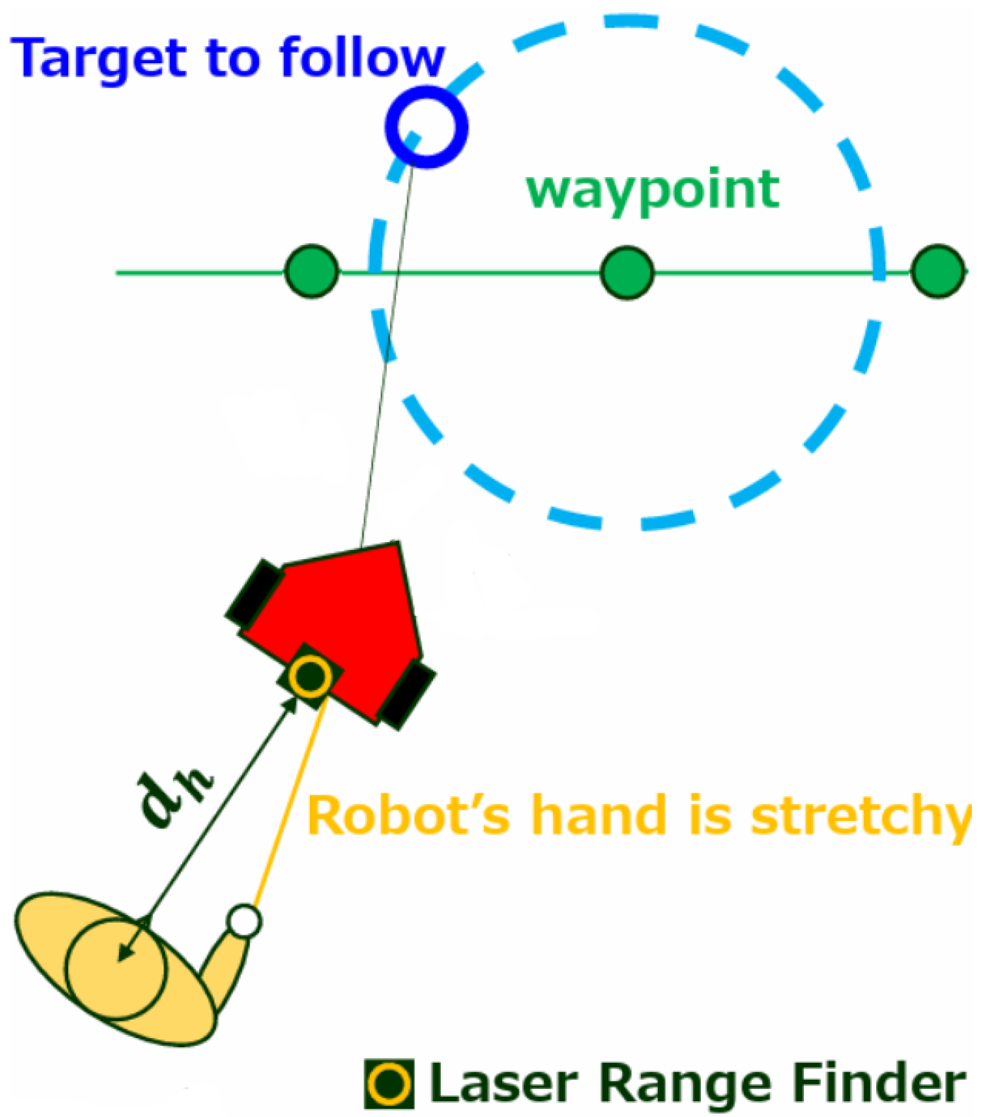
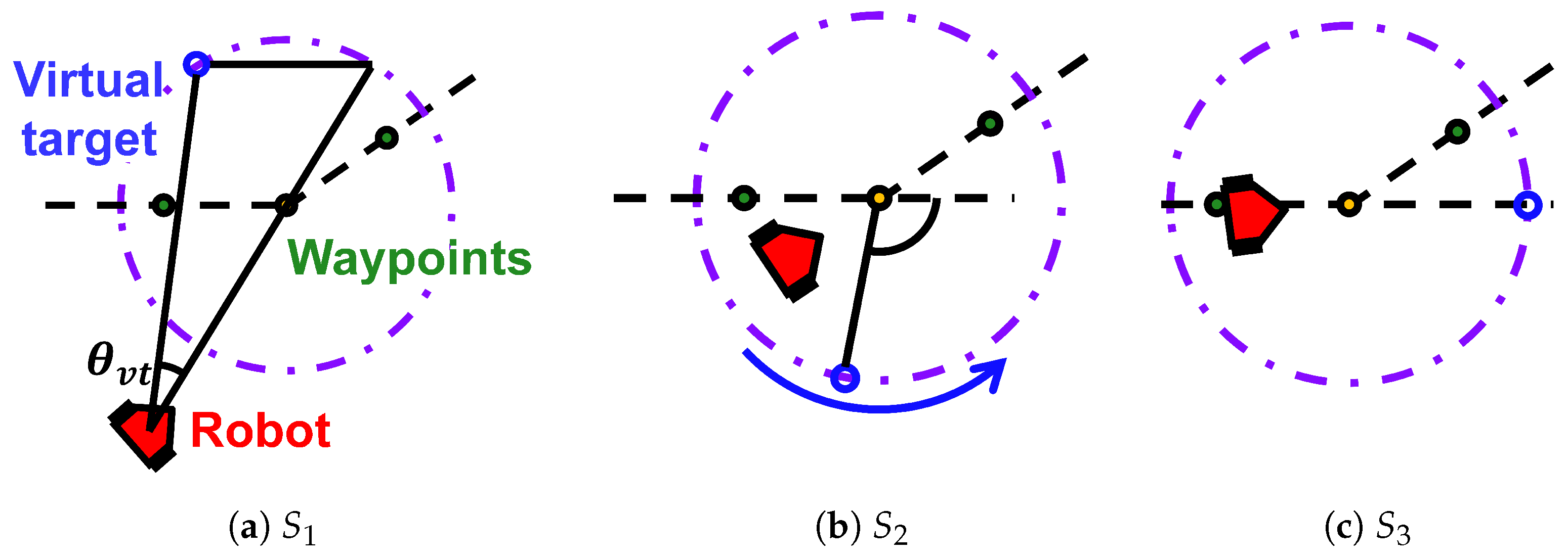
3.3. The Robot Side Method
3.4. Robot Avatar with Extendable Hand
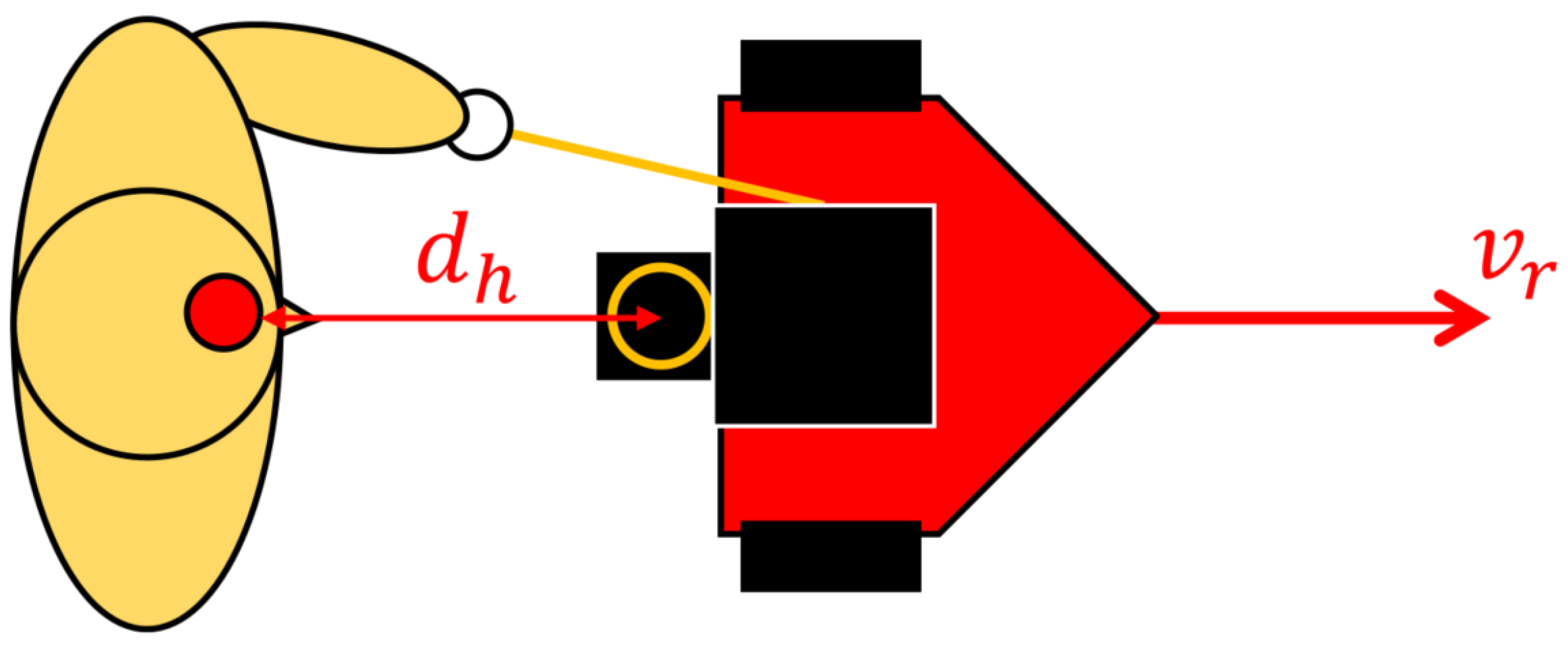
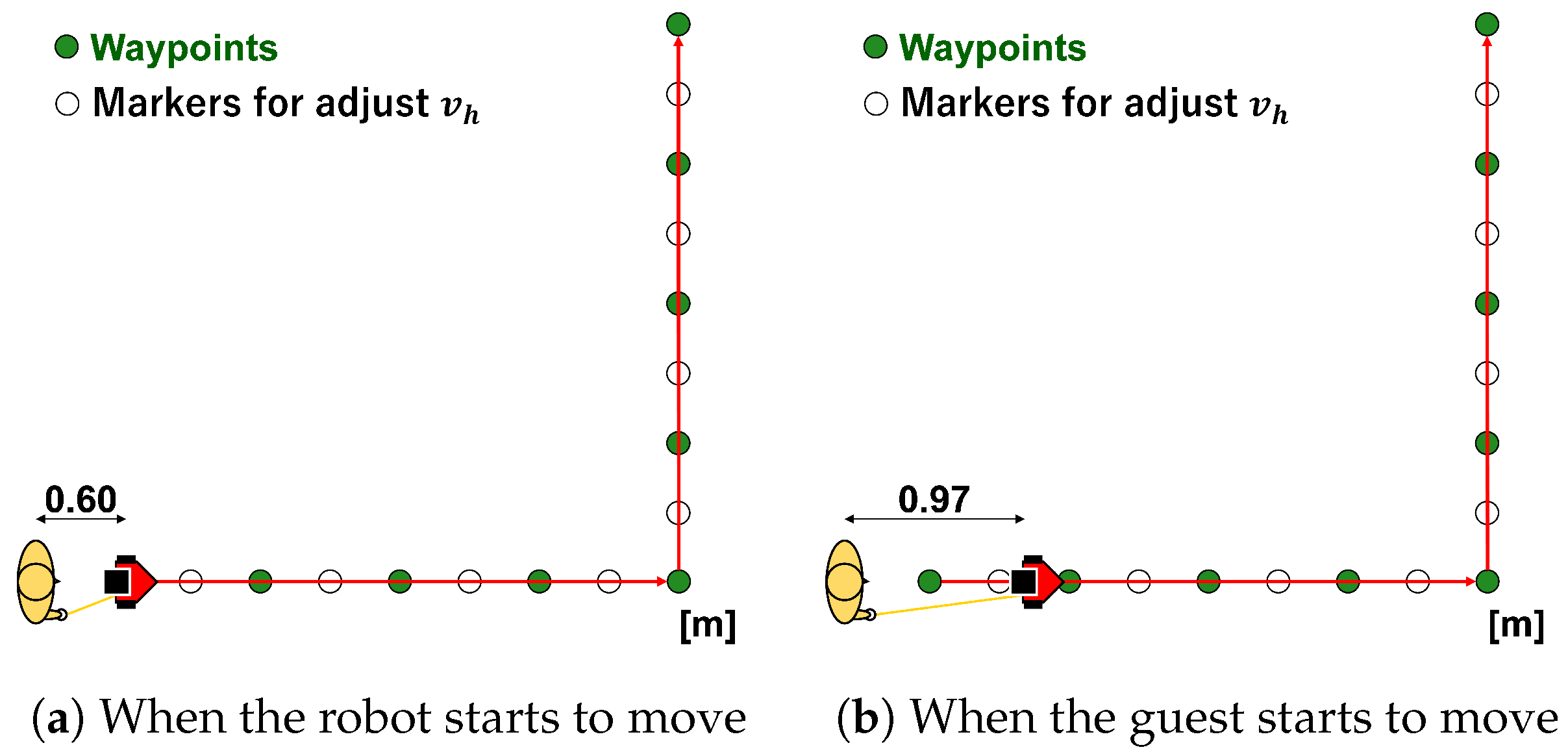
3.5. Controlling Human-Robot Distance by the Robot’s Speed
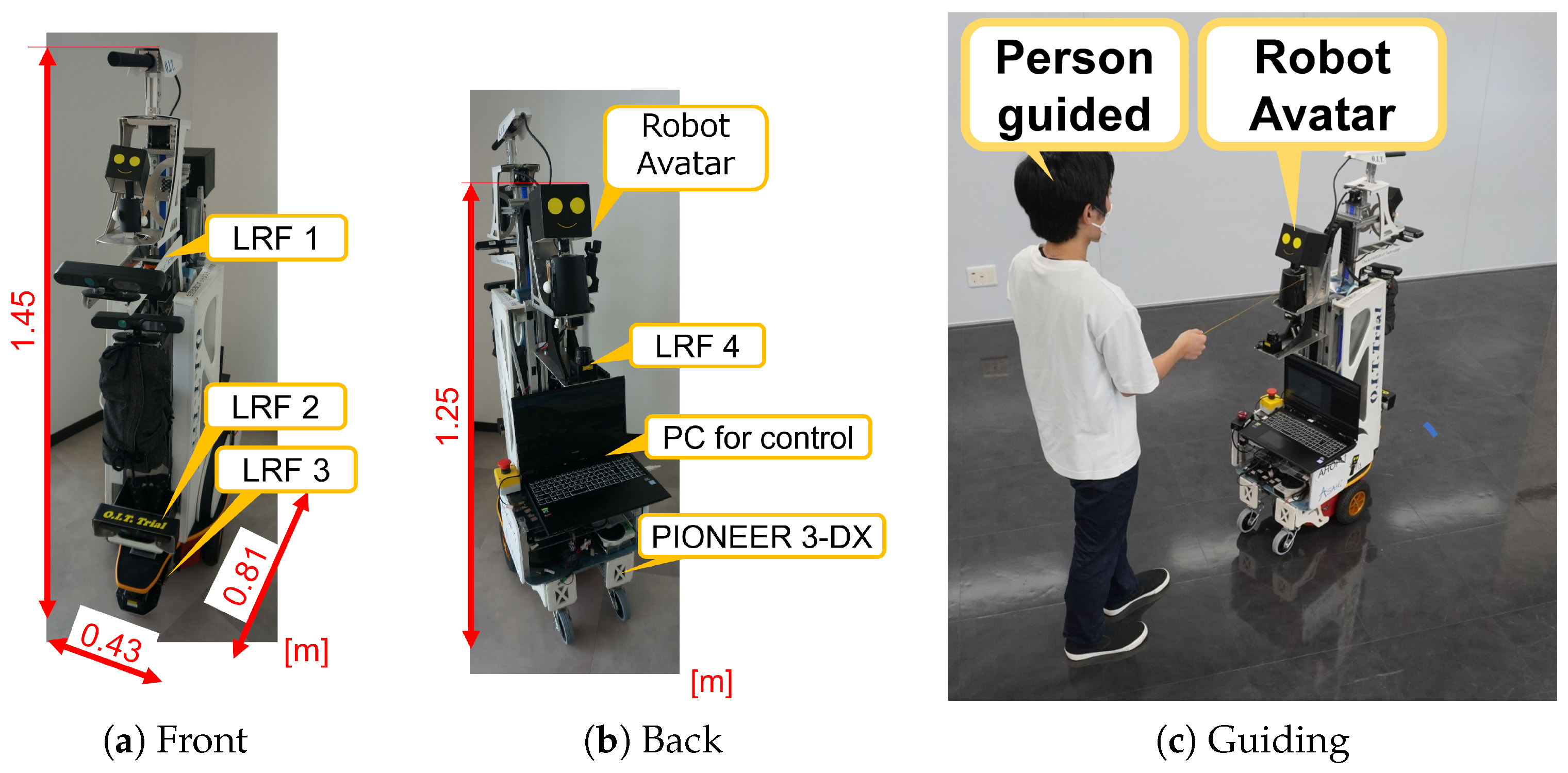
4. Implementation of the Robot “ASAHI ReBorn”
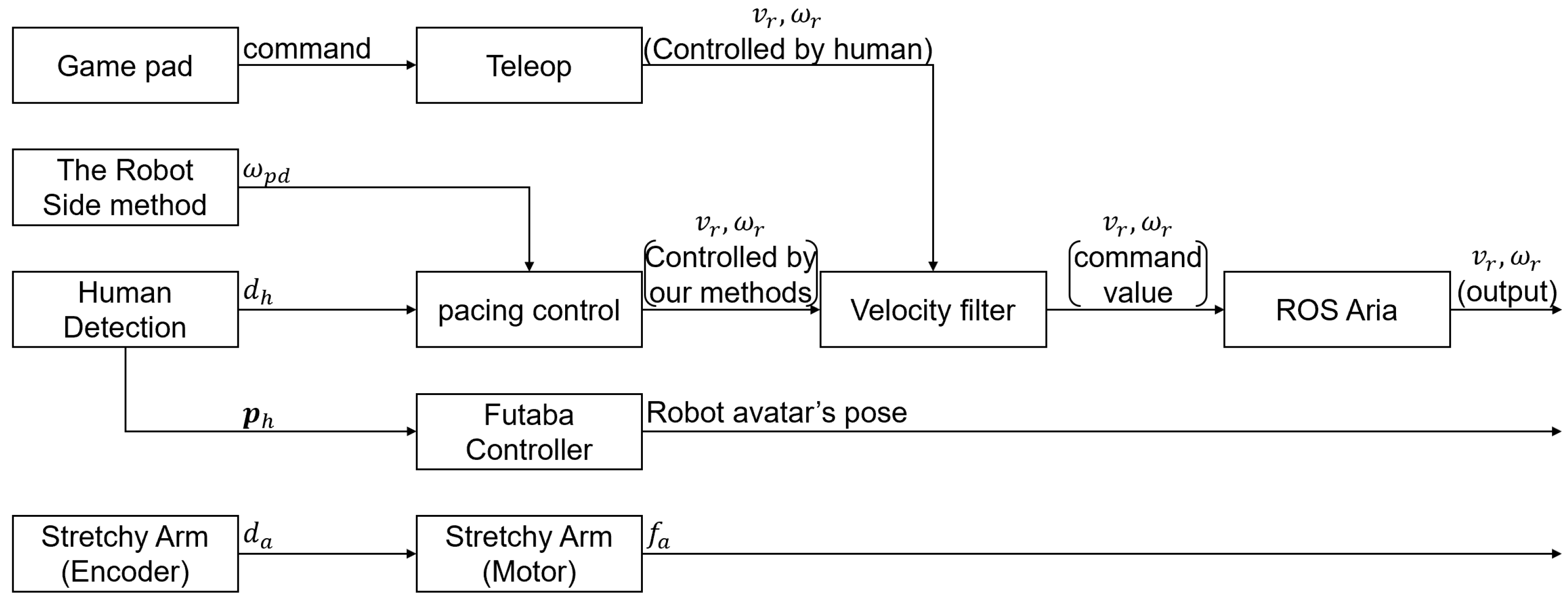
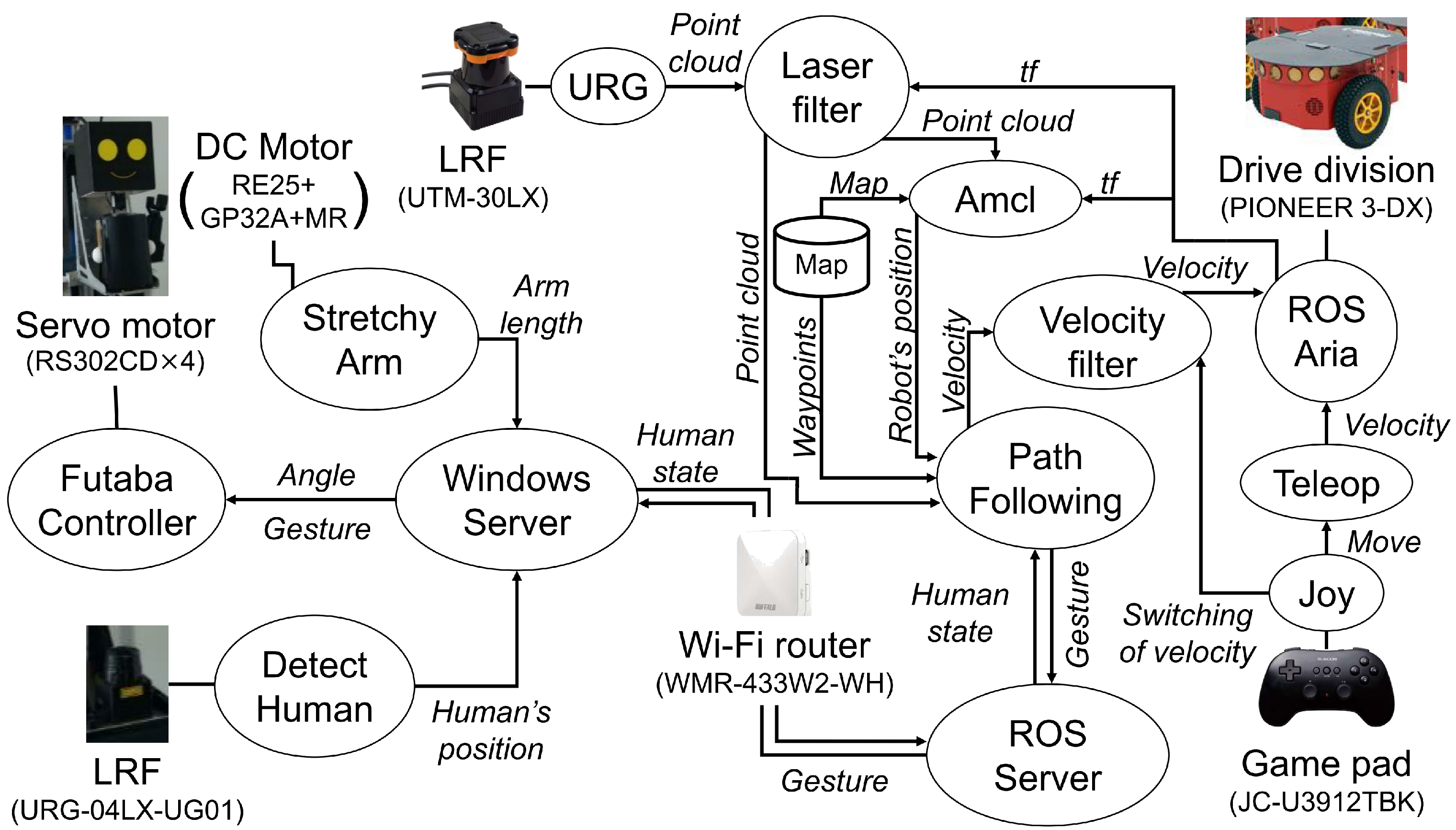
4.1. The System
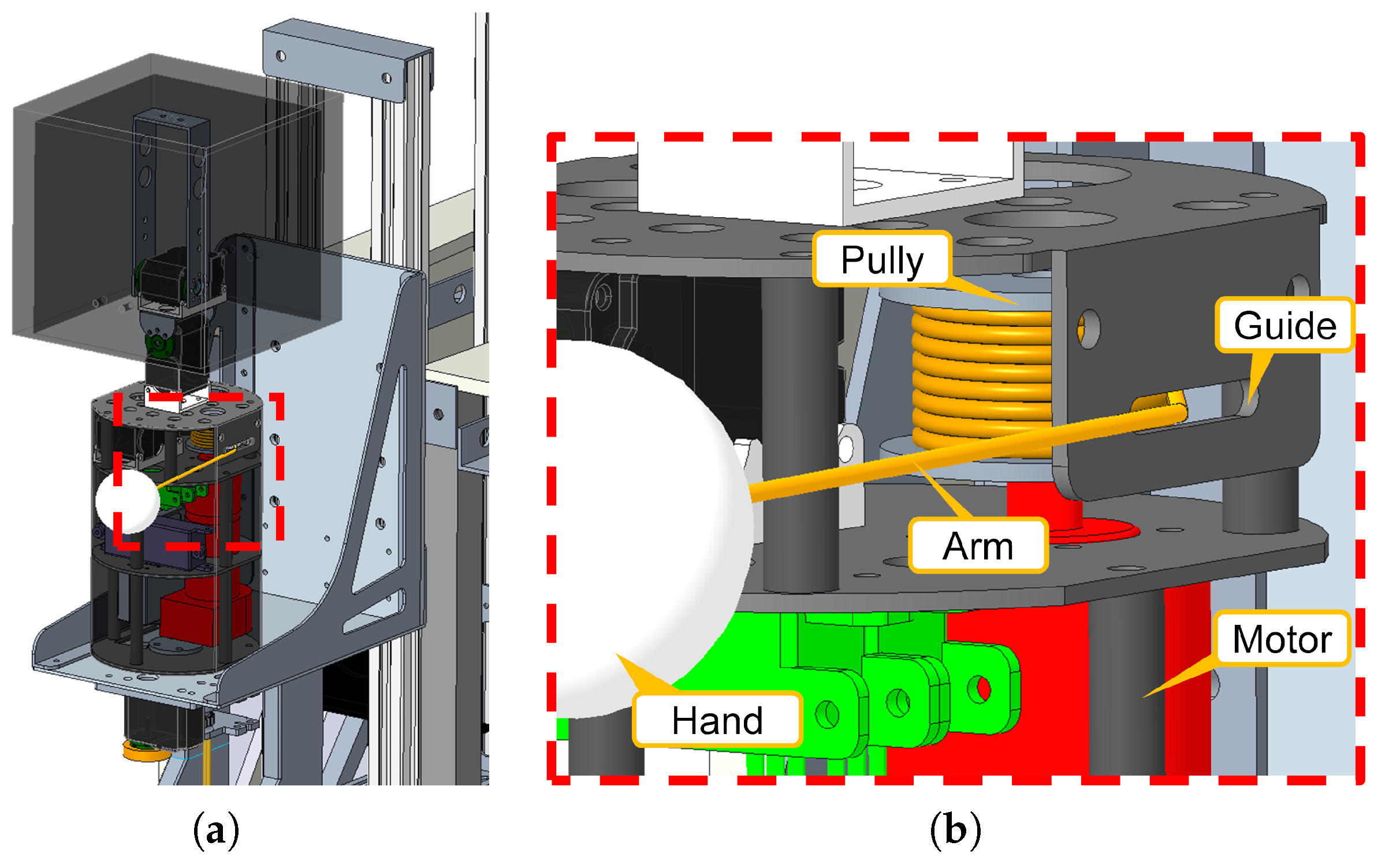
4.2. The Hardware
4.3. The Software
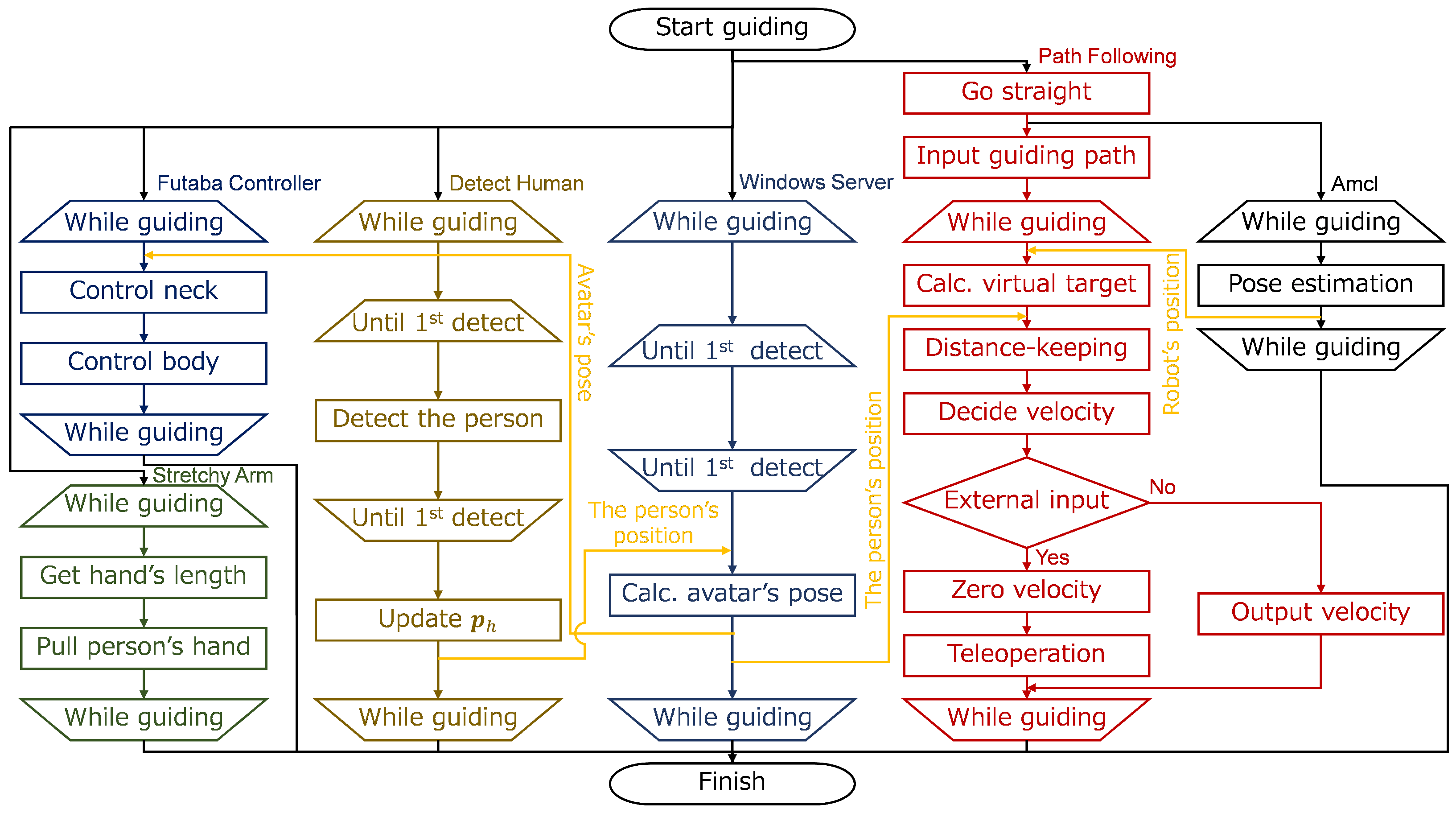
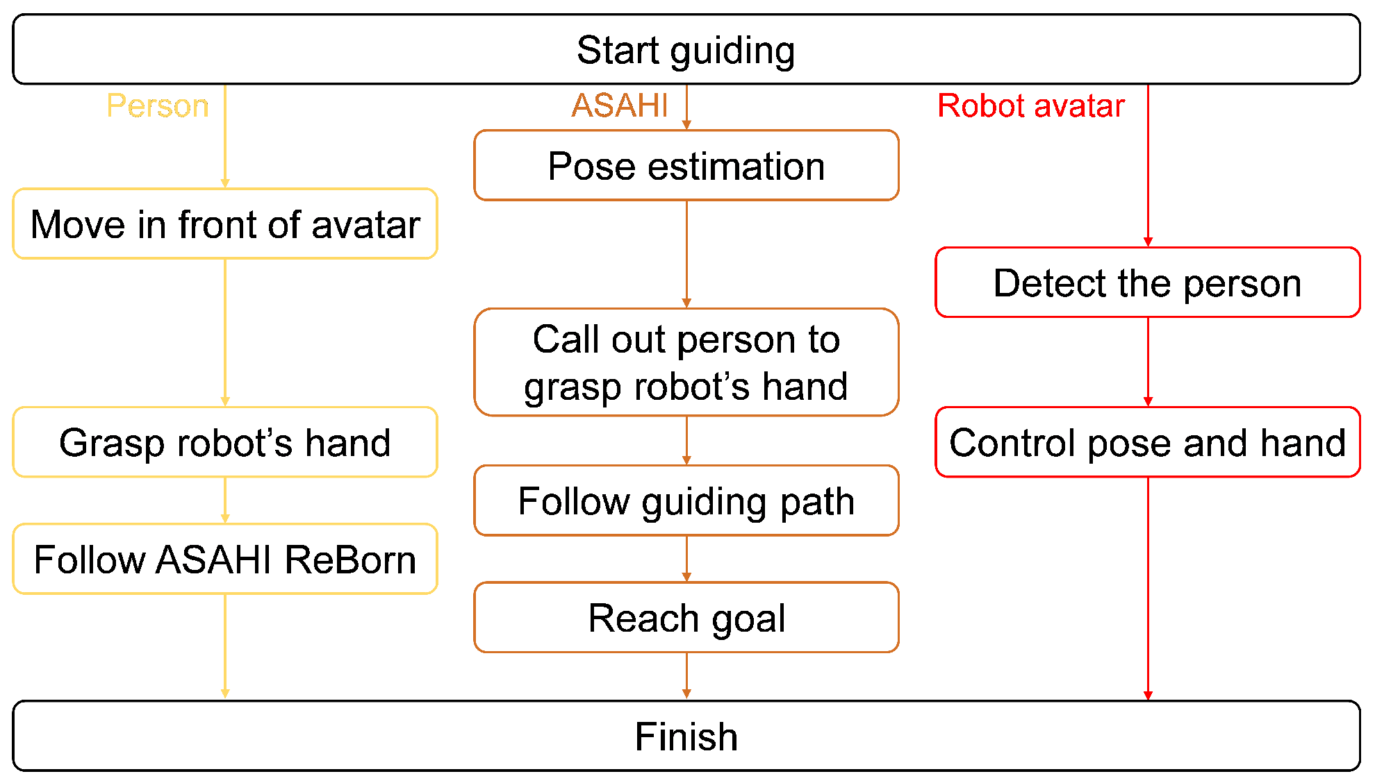
4.4. Route Guidance Flow
5. Simulation and Real Experiments
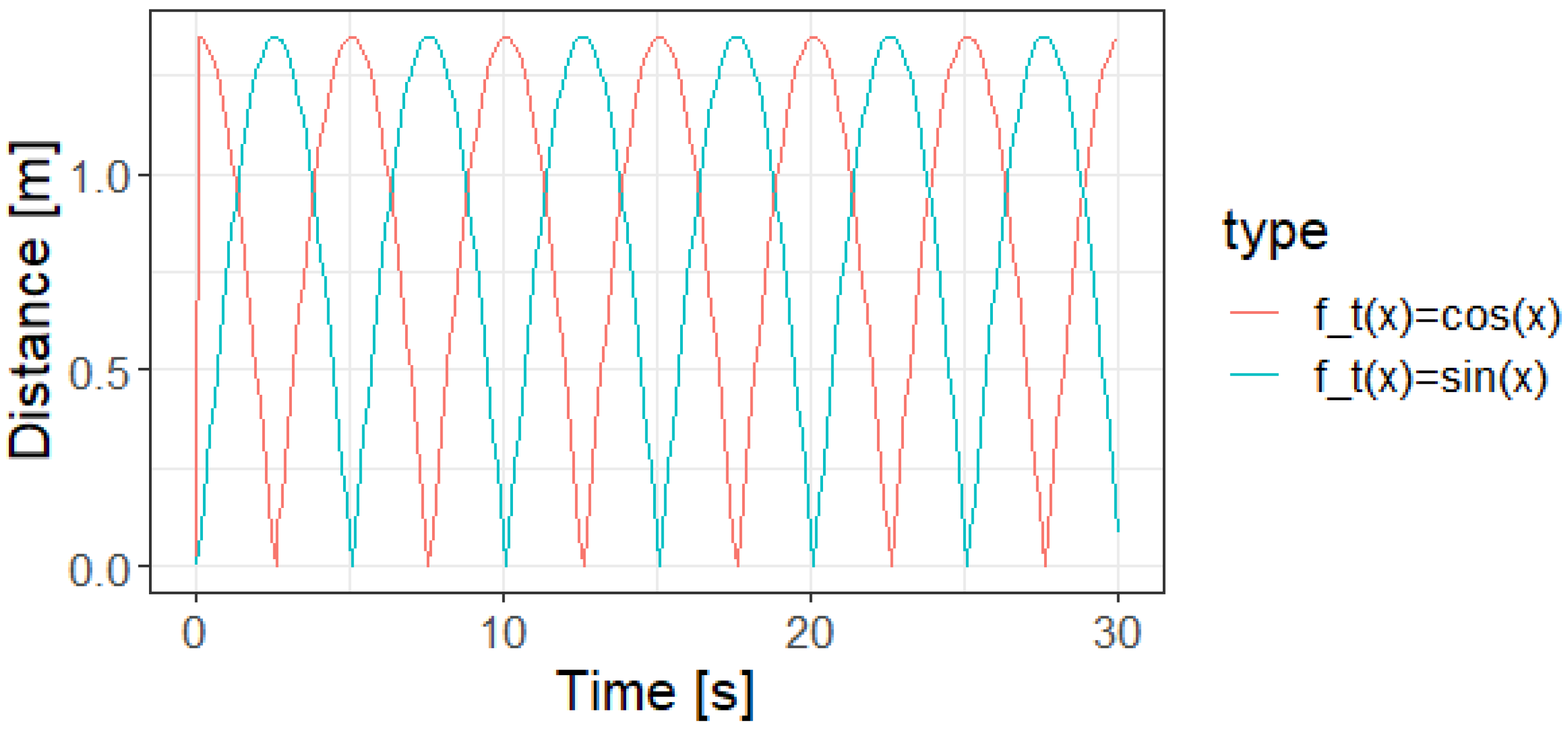
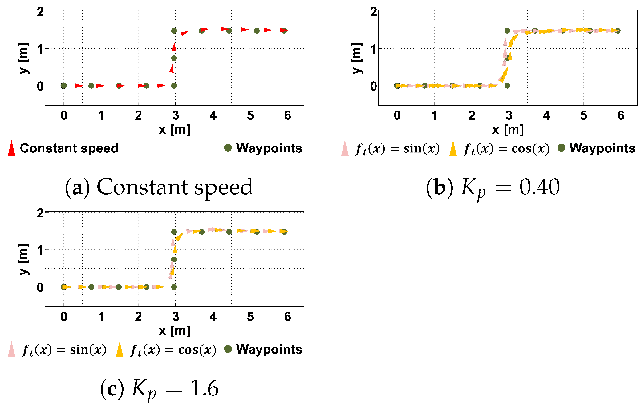
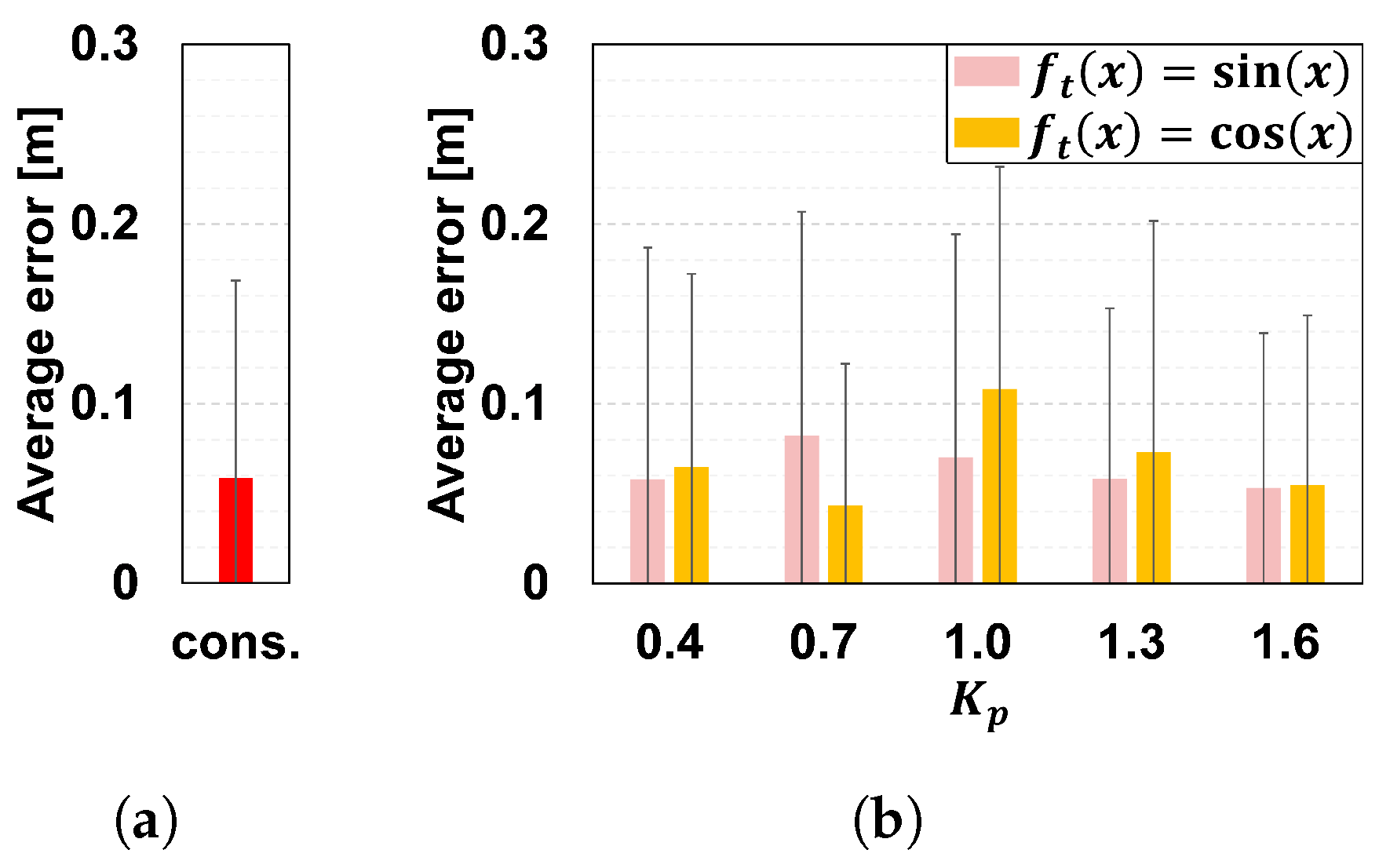
5.1. Simulation of the Distance Control with the Robot Side Method
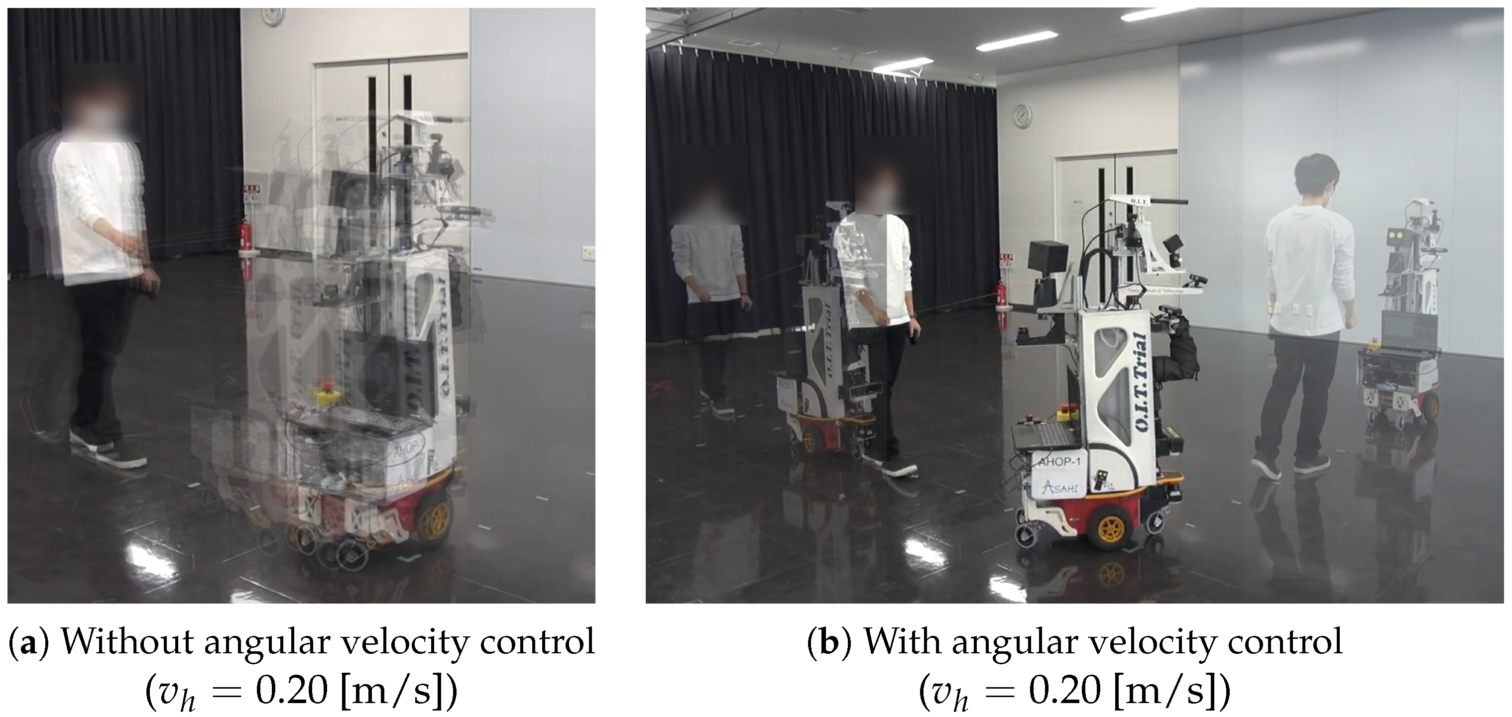
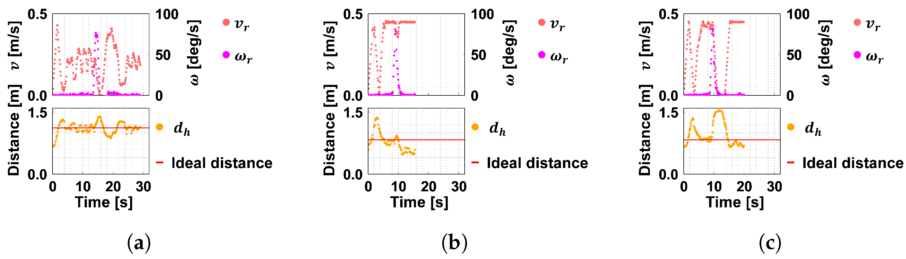
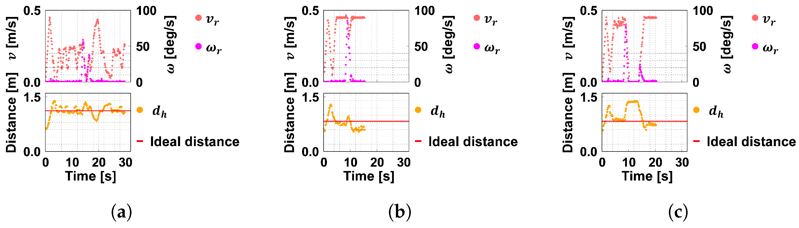
5.2. Implementation and Verification of the Distance Control on ASAHI ReBorn
- Walk at 0.20 [m/s] constantly from the start to the endpoint;
- Walk at 0.45 [m/s] constantly from the start to the endpoint;
- Walk at 0.45 [m/s], stop at the corner, then walk at 0.45 [m/s] again to the endpoint.
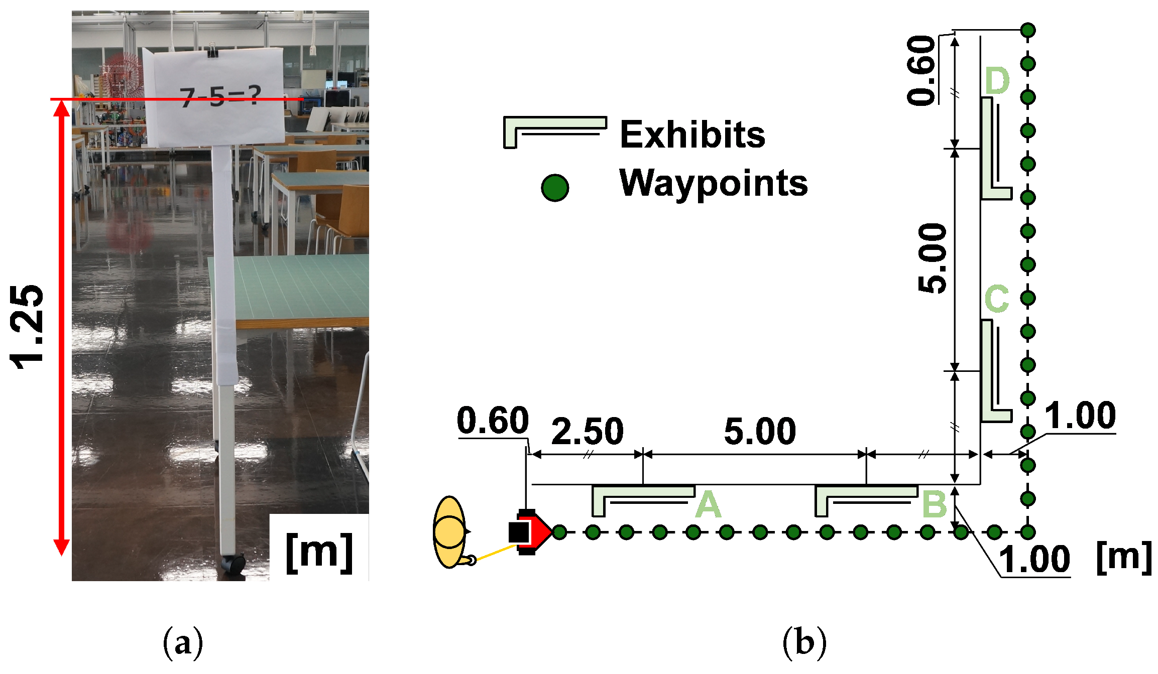
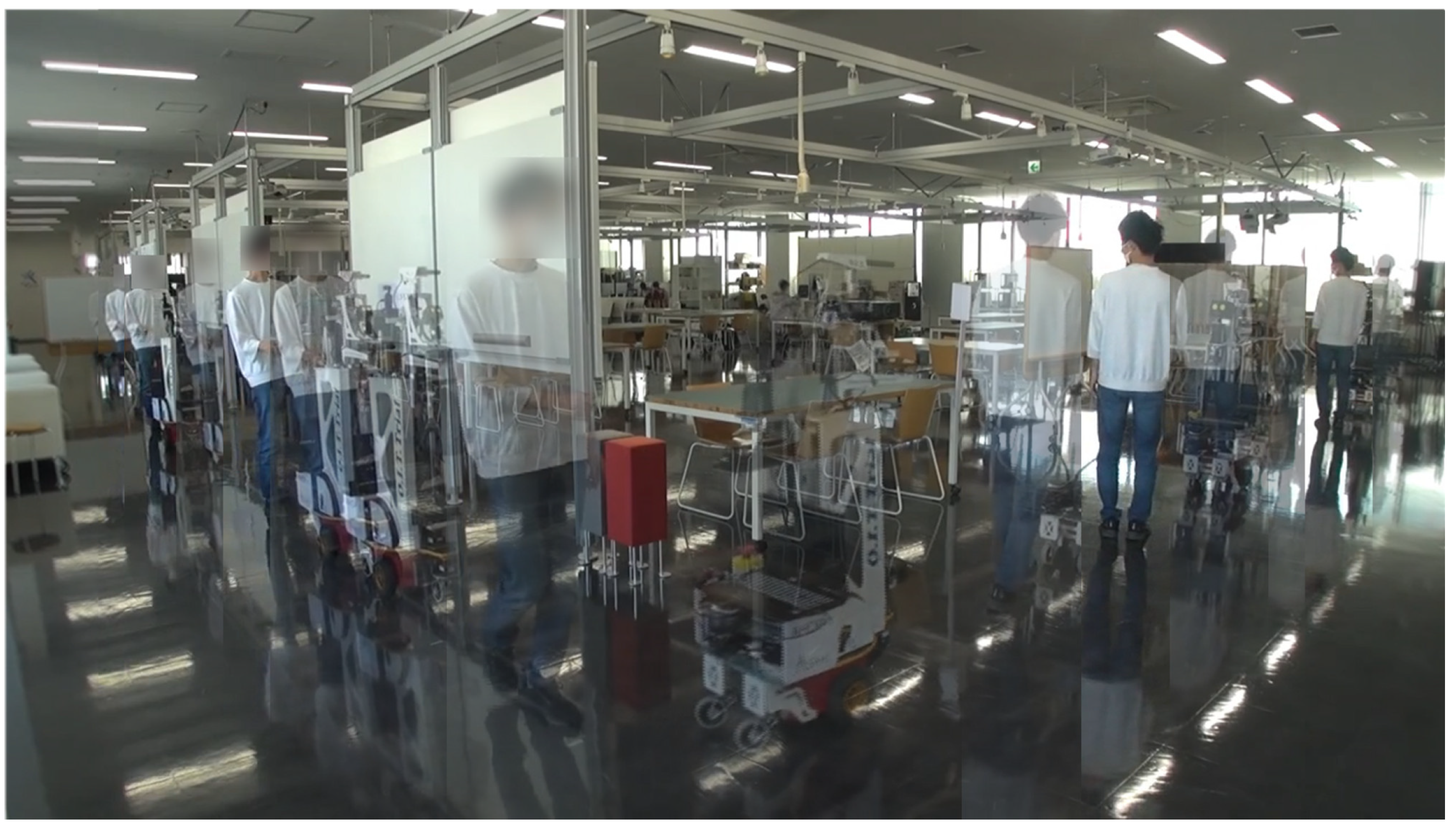
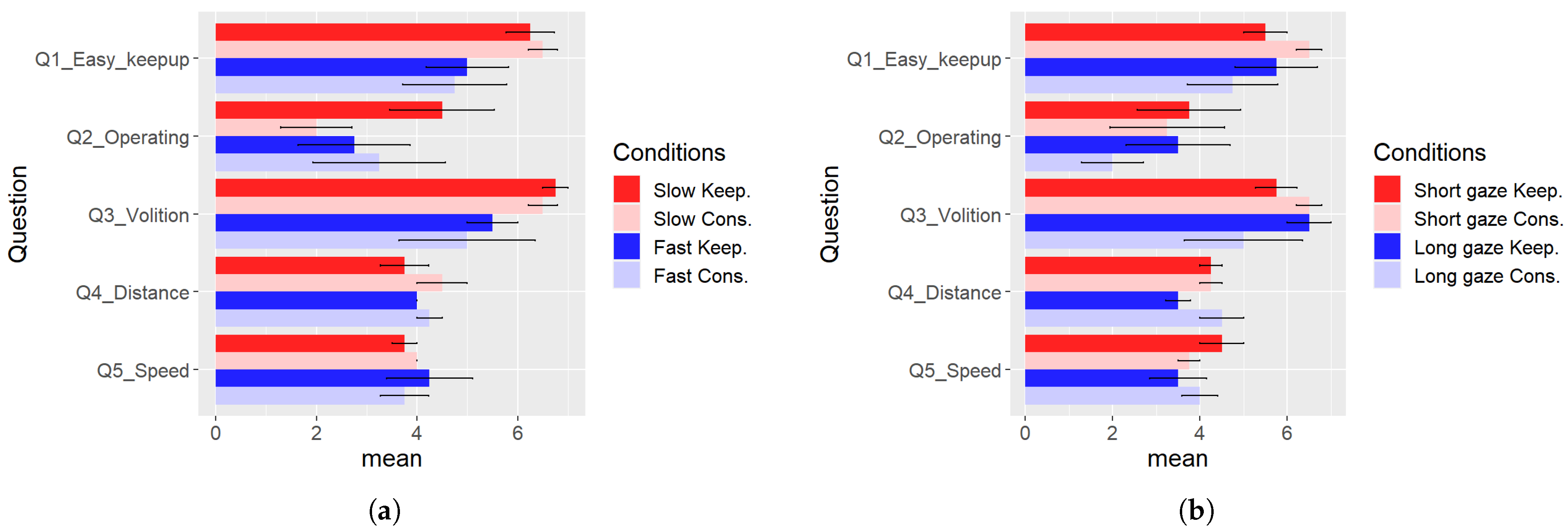
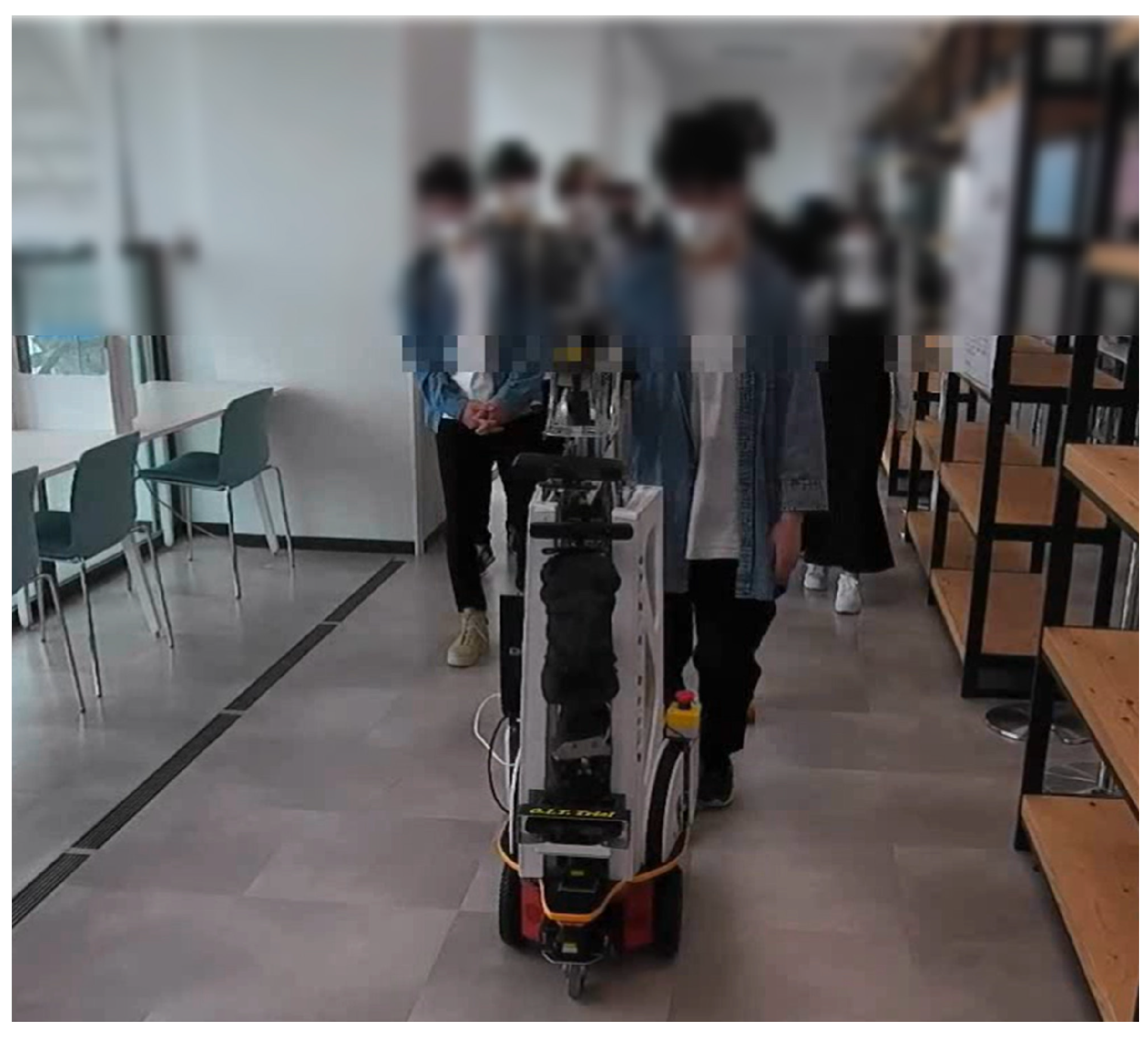
5.3. Experiments on Guided Tours around Exhibits
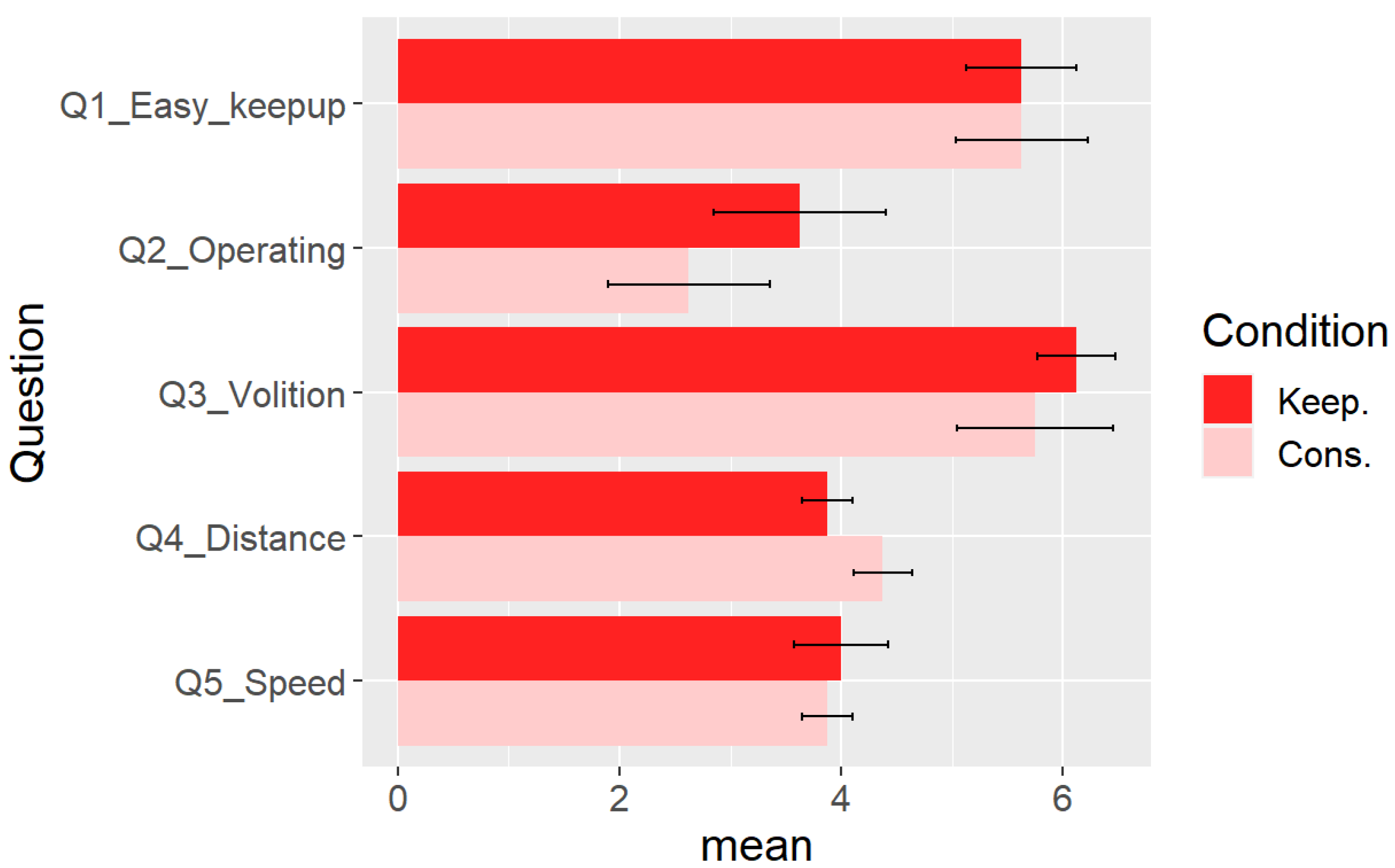
- Q1:
- It was easy to keep up with the robot. (1 = absolutely no, 7 = absolutely yes)[Q1_Easy_keepup];
- Q2:
- I felt like I was operating the robot myself. (1 = absolutely no, 7 = absolutely yes) [Q2_Operating];
- Q3:
- I could see the exhibit of my own volition. (1 = absolutely no, 7 = absolutely yes) [Q3_Volition];
- Q4:
- Subjective distance to the robot (1 = too far, 7 = too near) [Q4_Distance];
- Q5:
- Subjective speed of the robot (1 = too slow, 7 = too fast) [Q5_Speed].
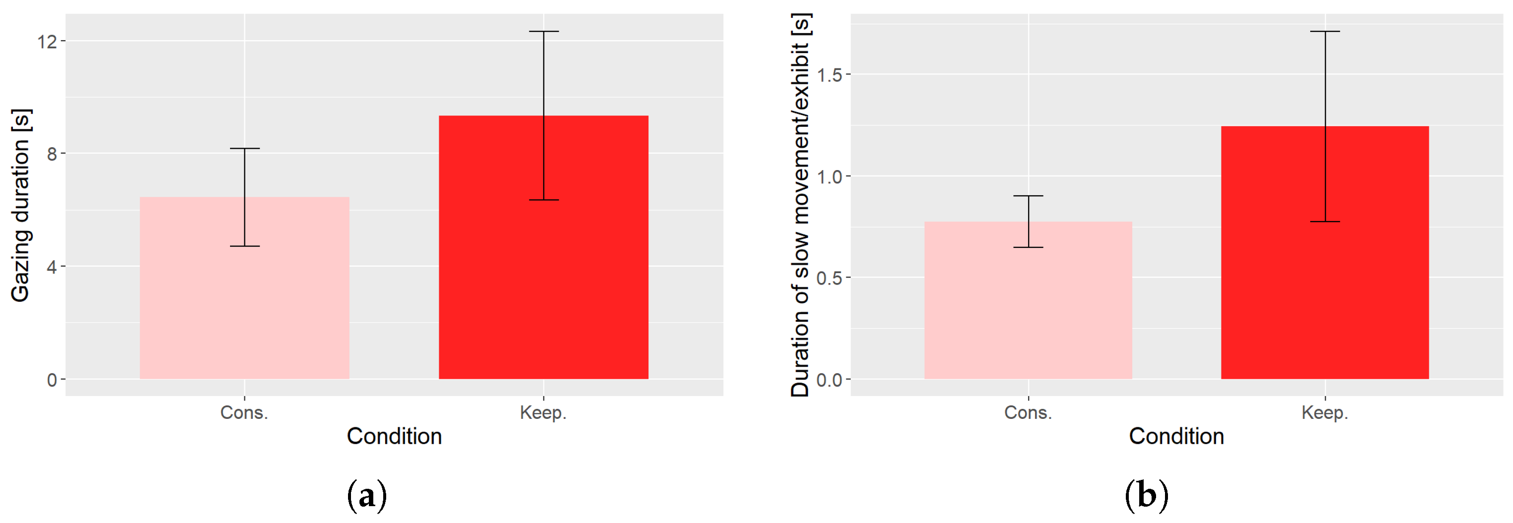
- The time that the guided person’s face was facing the direction of the exhibits. It was measured using a web camera with a gimbal mechanism attached to the robot (Feiyu pocket, 120° angle of view) and OpenPose 1.7.0 (https://github.com/CMU-Perceptual-Computing-Lab/openpose, accessed on 30 March 2024), the human pose detection software.
- The time the participant’s movement speed decreased near an exhibit. We considered the movement slow when [m/s].
6. Discussion
7. Conclusions
- The guide robot could hold hands with the guided person and lead them to the final destination.
- We realized distance control of the robot to move while keeping a good distance from the guest.
Author Contributions
Funding
Institutional Review Board Statement
Informed Consent Statement
Data Availability Statement
Conflicts of Interest
Appendix A
References
- Thrun, S.; Bennewitz, M.; Burgard, W.; Cremers, A.; Dellaert, F.; Fox, D.; Hahnel, D.; Rosenberg, C.; Roy, N.; Schulte, J.; et al. MINERVA: A second-generation museum tour-guide robot. In Proceedings of the 1999 IEEE International Conference on Robotics and Automation, Detroit, MI, USA, 10–15 May 1999; IEEE: New York, NY, USA, 1999; Volume 3, pp. 1999–2005. [Google Scholar] [CrossRef]
- Peñaa, K.M.; Cortés, B.B. GUI3DXBot: An Interactive Software Tool for a Tour-Guide Mobile Robot. Cienc. Ing. Ogran. 2020, 30, 59–74. [Google Scholar] [CrossRef]
- Schwering, A.; Krukar, J.; Li, R.; Anacta, V.J.; Fuest, S. Wayfinding Through Orientation. Spat. Cogn. Comput. 2017, 17, 273–303. [Google Scholar] [CrossRef]
- Basiri, A.; Winstanley, A.C.; Amirian, P. Landmark-based pedestrian navigation. In Proceedings of the 21st GIS Research UK (GISRUK) Conference, Liverpool, UK, 3–5 April 2013. [Google Scholar]
- Ko, E.; Kim, E.Y. A vision-based wayfinding system for visually impaired people using situation awareness and activity-based instructions. Sensors 2017, 17, 1882. [Google Scholar] [CrossRef] [PubMed]
- Cheraghi, S.A.; Namboodiri, V.; Walker, L. GuideBeacon: Beacon-based indoor wayfinding for the blind, visually impaired, and disoriented. In Proceedings of the 2017 IEEE International Conference on Pervasive Computing and Communications (PerCom), Kona, HI, USA, 13–17 March 2017; IEEE: New York, NY, USA; pp. 121–130. [Google Scholar] [CrossRef]
- Iio, T.; Satake, S.; Kanda, T.; Hayashi, K.; Ferreri, F.; Hagita, N. Human-Like Guide Robot that Proactively Explains Exhibits. Int. J. Soc. Robot. 2020, 12, 549–566. [Google Scholar] [CrossRef]
- Kanda, T.; Shiomi, M.; Miyashita, Z.; Ishiguro, H.; Hagita, N. A Communication Robot in a Shopping Mall. IEEE Trans. Robot. 2010, 26, 897–913. [Google Scholar] [CrossRef]
- Lee, M.K.; Kiesler, S.; Forlizzi, J. Receptionist or information kiosk: How do people talk with a robot? In Proceedings of the 2010 ACM Conference on Computer Supported Cooperative Work, Savannah, GA, USA, 6–10 February 2010; Association for Computing Machinery: New York, NY, USA; pp. 31–40. [Google Scholar] [CrossRef]
- Bazzano, F.; Lamberti, F. Human-robot interfaces for interactive receptionist systems and wayfinding applications. Robotics 2018, 7, 56. [Google Scholar] [CrossRef]
- Yonezawa, K.; Suzuki, Y.; Ueda, H. A Map Guidance System by Multiple Dialog Robots Cooperation. In Universal Access in Human-Computer Interaction. Design Methods, Tools, and Interaction Techniques for eInclusion. UAHCI 2013. Lecture Notes in Computer Science; Stephanidis, C., Antona, M., Eds.; Springer: Berlin/Heidelberg, Germany, 2013; Volume 8009, pp. 396–405. ISBN 978-3-642-39188-0. [Google Scholar] [CrossRef]
- Nguyen, T.H.; Tran, D.N.; Vo, D.L.; Mai, V.H.; Dao, X.Q. AI-Powered University: Design and Deployment of Robot Assistant for Smart Universities. J. Adv. Inf. Technol. 2022, 13, 78–84. [Google Scholar] [CrossRef]
- Thomas, T.; Doran, M.; Sakalaukus, J. An Autonomous Campus Tour Guide Robot as a Platform for Collaborative Engineering Design. In Proceedings of the 2010 Annual Conference & Exposition, Louisville, KY, USA, 20–23 June 2010; pp. 15.145.1–15.145.13. [Google Scholar]
- Ichihara, K.; Hasegawa, T.; Yuta, S.; Ichikawa, H.; Naruse, Y. Waypoint-Based Human-Tracking Navigation for Museum Guide Robot. J. Robot. Mechatronics 2022, 34, 1192–1204. [Google Scholar] [CrossRef]
- Shiomi, M.; Kanda, T.; Ishiguro, H.; Hagita, N. A Larger Audience, Please!—Encouraging people to listen to a guide robot. In Proceedings of the 2010 5th ACM/IEEE International Conference on Human-Robot Interaction, Savannah, GA, USA, 2–5 March 2010; IEEE: New York, NY, USA, 2010; pp. 31–38. [Google Scholar]
- Tobita, K.; Sagayama, K.; Mori, M.; Tabuchi, A. Structure and examination of the guidance robot LIGHBOT for visually impaired and elderly people. J. Robot. Mechatron. 2018, 30, 86–92. [Google Scholar] [CrossRef]
- Kayukawa, S.; Sato, D.; Murata, M.; Ishihara, T.; Kosugi, A.; Takagi, H.; Morishima, S.; Asakawa, C. How Users, Facility Managers, and Bystanders Perceive and Accept a Navigation Robot for Visually Impaired People in Public Buildings. In Proceedings of the 2022 31st IEEE International Conference on Robot and Human Interactive Communication (RO-MAN), Napoli, Italy, 29 August–2 September 2022; IEEE: New York, NY, USA, 2022; pp. 546–553. [Google Scholar] [CrossRef]
- Hasegawa, K.; Okada, M. Mako-no-te: Investigating Intersubjectivity with Side-by-Side Walking Robot. In Proceedings of the 2019 7th International Conference on Human-Agent Interaction (HAI ’19), Kyoto, Japan, 6–10 October 2019; Association for Computing Machinery: New York, NY, USA, 2019; pp. 217–219. [Google Scholar] [CrossRef]
- Hiroi, Y.; Ito, A. ASAHI: OK for failure A robot for supporting daily life, equipped with a robot avatar. In Proceedings of the 2013 8th ACM/IEEE International Conference on Human-Robot Interaction (HRI), Tokyo, Japan, 3–6 March 2013; IEEE: New York, NY, USA, 2013; pp. 141–142. [Google Scholar] [CrossRef]
- Burgard, W.; Cremers, A.B.; Fox, D.; Hähnel, D.; Lakemeyer, G.; Schulz, D.; Steiner, W.; Thrun, S. The Interactive Museum Tour-Guide Robot. In Proceedings of the 1998 National Conference on Artificial Intelligence (AAAI-98), Madison, WI, USA, 26–30 July 1998; AAAI: Washington, DC, USA, 1998. [Google Scholar]
- Burgard, W.; Cremers, A.B.; Fox, D.; Hähnel, D.; Lakemeyer, G.; Schulz, D.; Steiner, W.; Thrun, S. Experiences with an interactive museum tour-guide robot. Artif. Intell. 1999, 114, 3–55. [Google Scholar] [CrossRef]
- Schraft, R.D.; Graf, B.; Traub, A.; John, D.D.I. A mobile robot platform for assistance and entertainment. Ind. Robot. Int. J. 2001, 28, 29–35. [Google Scholar] [CrossRef]
- Rodriguez-Losada, D.; Matia, F.; Galan, R.; Hernando, M.; Montero, J.M.; Lucas, J.M. Urbano, an interactive mobile tour-guide robot. In Advances in Service Robotics; IntechOpen: London, UK, 2008; pp. 229–252. [Google Scholar]
- Kim, G.; Chung, W.; Kim, K.R.; Kim, M.; Han, S.; Shinn, R.H. The autonomous tour-guide robot Jinny. In Proceedings of the 2004 IEEE/RSJ International Conference on Intelligent Robots and Systems (IROS), Sendai, Japan, 28 September–2 October 2004; IEEE: New York, NY, USA, 2004; Volume 4, pp. 3450–3455. [Google Scholar] [CrossRef]
- Shiomi, M.; Kanda, T.; Ishiguro, H.; Hagita, N. Interactive humanoid robots for a science museum. In Proceedings of the 2006 1st ACM SIGCHI/SIGART Conference on Human-Robot Interaction, Salt Lake City, UT, USA, 2–3 March 2006; Association of Computing Machinery: New York, NY, USA, 2006; pp. 305–312. [Google Scholar] [CrossRef]
- Kuno, Y.; Sadazuka, K.; Kawashima, M.; Yamazaki, K.; Yamazaki, A.; Kuzuoka, H. Museum guide robot based on sociological interaction analysis. In Proceedings of the 2007 ACM SIGCHI Conference on Human Factors in Computing Systems, San Jose, CA, USA, 28 April–3 May 2007; Association of Computing Machinery: New York, NY, USA, 2007; pp. 1191–1194. [Google Scholar] [CrossRef]
- Díaz-Boladeras, M.; Paillacho, D.; Angulo, C.; Torres, O.; González-Diéguez, J.; Albo-Canals, J. Evaluating group-robot interaction in crowded public spaces: A week-long exploratory study in the wild with a humanoid robot guiding visitors through a science museum. Int. J. Humanoid Robot. 2015, 12, 1550022. [Google Scholar] [CrossRef]
- Ghosh, M.; Kuzuoka, H. An ethnomethodological study of a museum guide robot’s attempt at engagement and disengagement. J. Robot. 2014, 2014, 876439:1–876439:20. [Google Scholar] [CrossRef]
- Karreman, D.; Ludden, G.; Evers, V. Visiting cultural heritage with a tour guide robot: A user evaluation study in-the-wild. In Social Robotics. ICSR 2015, Paris, France, 26–30 October 2015, Lecture Notes in Computer Science; Tapus, A., André, E., Martin, J.C., Ferland, F., Ammi, M., Eds.; Springer: Cham, Switzerland, 2015; pp. 317–326. [Google Scholar] [CrossRef]
- Rashed, M.G.; Suzuki, R.; Lam, A.; Kobayashi, Y.; Kuno, Y. Toward museum guide robots proactively initiating interaction with humans. In Proceedings of the 2015 Tenth Annual ACM/IEEE International Conference on Human-Robot Interaction Extended Abstracts, Portland, OR, USA, 2–5 March 2015; Association for Computing Machinery: New York, NY, USA, 2015; pp. 1–2. [Google Scholar] [CrossRef]
- Taheri, H.; Xia, Z.C. SLAM; definition and evolution. Eng. Appl. Artif. Intell. 2021, 97, 104032:1–104032:25. [Google Scholar] [CrossRef]
- Aggarwal, S.; Kumar, N. Path planning techniques for unmanned aerial vehicles: A review, solutions, and challenges. Comput. Commun. 2020, 149, 270–299. [Google Scholar] [CrossRef]
- Malik, M.; Malik, M.K.; Mehmood, K.; Makhdoom, I. Automatic speech recognition: A survey. Multimed. Tools Appl. 2021, 80, 9411–9457. [Google Scholar] [CrossRef]
- Kaur, N.; Singh, P. Conventional and contemporary approaches used in text to speech synthesis: A review. Artif. Intell. Rev. 2023, 56, 5837–5880. [Google Scholar] [CrossRef]
- Kortli, Y.; Jridi, M.; Al Falou, A.; Atri, M. Face recognition systems: A survey. Sensors 2020, 20, 342. [Google Scholar] [CrossRef]
- Liu, Y.; Mohammadi, G.; Song, Y.; Johal, W. Speech-based gesture generation for robots and embodied agents: A scoping review. In Proceedings of the 2021 the 9th International Conference on Human-Agent Interaction, Online, 9–11 November 2021; Association for Computing Machinery: New York, NY, USA, 2021; pp. 31–38. [Google Scholar] [CrossRef]
- Dai, Y.; Yu, H.; Jiang, Y.; Tang, C.; Li, Y.; Sun, J. A survey on dialog management: Recent advances and challenges. arXiv 2020, arXiv:2005.02233. [Google Scholar]
- Gehle, R.; Pitsch, K.; Dankert, T.; Wrede, S. How to open an interaction between robot and museum visitor? Strategies to establish a focused encounter in HRI. In Proceedings of the 2017 ACM/IEEE International Conference on Human-Robot Interaction, Vienna, Austria, 6–9 March 2017; Association for Computing Machinery: New York, NY, USA, 2021; pp. 187–195. [Google Scholar] [CrossRef]
- Del Duchetto, F.; Baxter, P.; Hanheide, M. Lindsey the tour guide robot-usage patterns in a museum long-term deployment. In Proceedings of the 2019 28th IEEE International Conference on Robot and Human Interactive Communication (RO-MAN), New Delhi, India, 14–18 October 2019; IEEE: New York, NY, USA, 2019; pp. 1–8. [Google Scholar] [CrossRef]
- Vásquez, B.P.E.A.; Matía, F. A tour-guide robot: Moving towards interaction with humans. Eng. Appl. Artif. Intell. 2020, 88, 103356:1–103356:17. [Google Scholar] [CrossRef]
- Roerdink, M.; van Ulzen, N.R.; de Poel, H. When two become one: Spontaneous pattern formation in side-by-side and hand-in-hand walking. In Proceedings of the Joint Action Meeting, London, UK, 22–26 July 2017; p. 122. [Google Scholar]
- Sylos-Labini, F.; d’Avella, A.; Lacquaniti, F.; Ivanenko, Y. Human-Human Interaction Forces and Interlimb Coordination during Side-by-Side Walking with Hand Contact. Front. Physiol. 2018, 9, 179:1–179:14. [Google Scholar] [CrossRef] [PubMed]
- Kochigami, K.; Jiang, J.; Kakehashi, Y.; Au, C.; Kakiuchi, Y.; Okada, K.; Inaba, M. Walking together hand in hand: Design and evaluation of autonomous robot system that a robot recognizes moving direction with a child’s assistance of pulling its hand. In Proceedings of the 2015 IEEE/SICE International Symposium on System Integration (SII), Nagoya, Japan, 11–13 December 2015; IEEE: New York, NY, USA, 2015; pp. 738–743. [Google Scholar] [CrossRef]
- Hieida, C.; Abe, K.; Nagai, T.; Omori, T. Walking hand-in-hand helps relationship building between child and robot. J. Robot. Mechatronics 2020, 32, 8–20. [Google Scholar] [CrossRef]
- Nakane, A.; Yanokura, I.; Ichikura, A.; Okada, K.; Inaba, M. Development of Robot Guidance System Using Hand-holding with Human and Measurement of Psychological Security. In Proceedings of the 2023 32nd IEEE International Conference on Robot and Human Interactive Communication (RO-MAN), Busan, Republic of Korea, 28–31 August 2023; IEEE: New York, NY, USA, 2023; pp. 2030–2036. [Google Scholar] [CrossRef]
- Bönsch, A.; Hashem, D.; Ehret, J.; Kuhlen, T.W. Being Guided or Having Exploratory Freedom: User Preferences of a Virtual Agent’s Behavior in a Museum. In Proceedings of the 2021 ACM International Conference on Intelligent Virtual Agents (IVA ’21), Online, 14 September 2021; Association for Computing Machinery: New York, NY, USA, 2021; pp. 33–40. [Google Scholar] [CrossRef]
- Reinhardt, J.; Schmidtler, J.; Körber, M.; Bengler, K. Follow Me! Wie Roboter Menschen führen sollen. In Zeitschrift für Arbeitswissenschaft; Springer: Berlin/Heidelberg, Germany, 2016; Volume 70, pp. 203–210. [Google Scholar] [CrossRef]
- Wakabayashi, H.; Hiroi, Y.; Miyawaki, K.; Ito, A. Path following algorithm with small error for guide robot. In Robot Intelligence Technology and Applications 7. RiTA 2022, Gold Coast, Australia, 7–9 December 2022, Lecture Notes in Networks and Systems; Springer: Cham, Switzerland, 2023; Volume 642, pp. 56–67. [Google Scholar] [CrossRef]
- Fujiwara, Y.; Hiroi, Y.; Tanaka, Y.; Ito, A. Development of a Mobile Robot Moving on a Handrail—Control for Preceding a Person Keeping a Distance. In Proceedings of the 2015 24th IEEE International Symposium on Robot and Human Interactive Communication (RO-MAN), Kobe, Japan, 31 August 2015; IEEE: New York, NY, USA, 2023; pp. 413–418. [Google Scholar] [CrossRef]
- Hiroi, Y.; Ito, A.; Nakano, E. Evaluation of robot-avatar-based user-familiarity improvement for elderly people. Kansei Eng. Int. 2009, 8, 59–66. [Google Scholar] [CrossRef]
- Hiroi, Y.; Matsunaka, S.; Ito, A. A mobile robot system with semi-autonomous navigation using simple and robust person following behavior. J. Man, Mach. Technol. 2012, 1, 44–62. [Google Scholar] [CrossRef]
- Hiroi, Y.; Ito, A. A Pedestrian Avoidance Method Considering Personal Space for a Guide Robot. Robotics 2019, 8, 97. [Google Scholar] [CrossRef]
- Kerr, J.; Nickels, K. Robot operating systems: Bridging the gap between human and robot. In Proceedings of the 2012 44th Southeastern Symposium on System Theory (SSST), Jacksonville, FL, USA, 11–13 March 2012; IEEE: New York, NY, USA, 2012; pp. 99–104. [Google Scholar] [CrossRef]
- Cowan, N. The magical number 4 in short-term memory: A reconsideration of mental storage capacity. Behav. Brain Sci. 2001, 24, 87–114. [Google Scholar] [CrossRef]
- Belk, R. Ethical issues in service robotics and artificial intelligence. Serv. Ind. J. 2021, 41, 860–876. [Google Scholar] [CrossRef]
- Pierce, J.; Wong, R.Y.; Merrill, N. Sensor illumination: Exploring design qualities and ethical implications of smart cameras and image/video analytics. In Proceedings of the 2020 CHI Conference on Human Factors in Computing Systems, Honolulu, HI, USA, 25–30 April 2020; Association for Computing Machinery: New York, NY, USA, 2020; pp. 1–19. [Google Scholar] [CrossRef]
- Luenberger, D.G. Dynamic Systems; John Wiley & Sons: Hoboken, NJ, USA, 1979. [Google Scholar]


Disclaimer/Publisher’s Note: The statements, opinions and data contained in all publications are solely those of the individual author(s) and contributor(s) and not of MDPI and/or the editor(s). MDPI and/or the editor(s) disclaim responsibility for any injury to people or property resulting from any ideas, methods, instructions or products referred to in the content. |
© 2024 by the authors. Licensee MDPI, Basel, Switzerland. This article is an open access article distributed under the terms and conditions of the Creative Commons Attribution (CC BY) license (https://creativecommons.org/licenses/by/4.0/).
Share and Cite
Wakabayashi, H.; Hiroi, Y.; Miyawaki, K.; Ito, A. Development of a Personal Guide Robot That Leads a Guest Hand-in-Hand While Keeping a Distance. Sensors 2024, 24, 2345. https://doi.org/10.3390/s24072345
Wakabayashi H, Hiroi Y, Miyawaki K, Ito A. Development of a Personal Guide Robot That Leads a Guest Hand-in-Hand While Keeping a Distance. Sensors. 2024; 24(7):2345. https://doi.org/10.3390/s24072345
Chicago/Turabian StyleWakabayashi, Hironobu, Yutaka Hiroi, Kenzaburo Miyawaki, and Akinori Ito. 2024. "Development of a Personal Guide Robot That Leads a Guest Hand-in-Hand While Keeping a Distance" Sensors 24, no. 7: 2345. https://doi.org/10.3390/s24072345