
Thermalization of Mesh Reinforced Ultra-Thin Al-Coated Plastic Films: A Parametric Study Applied to the Athena X-IFU Instrument

 , , ,
, , ,  , , and
Abstract
:1. Introduction
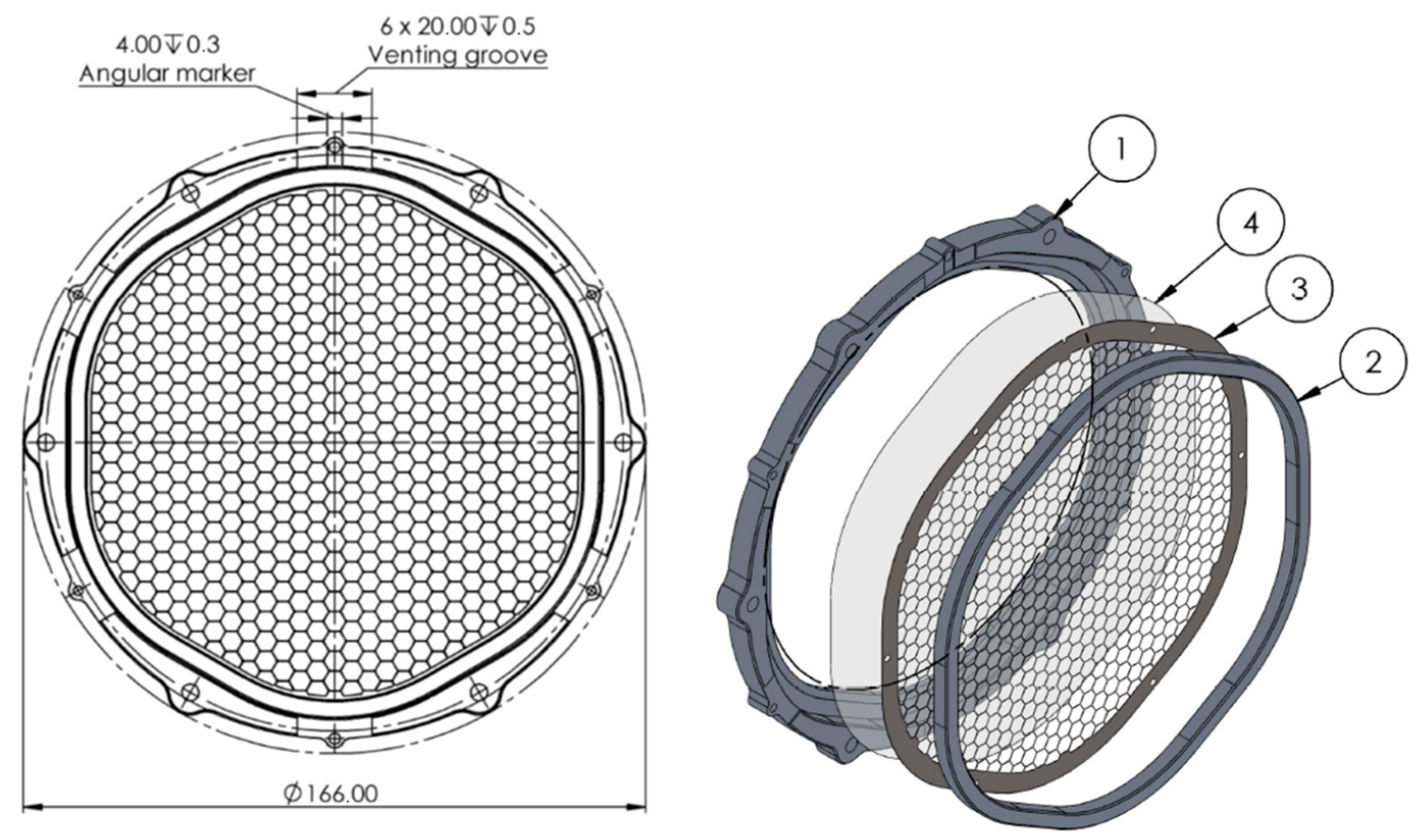
2. Baseline Design and Cases Studied
- Raising the temperature of the external frame and heating the filter by conduction through the mesh;
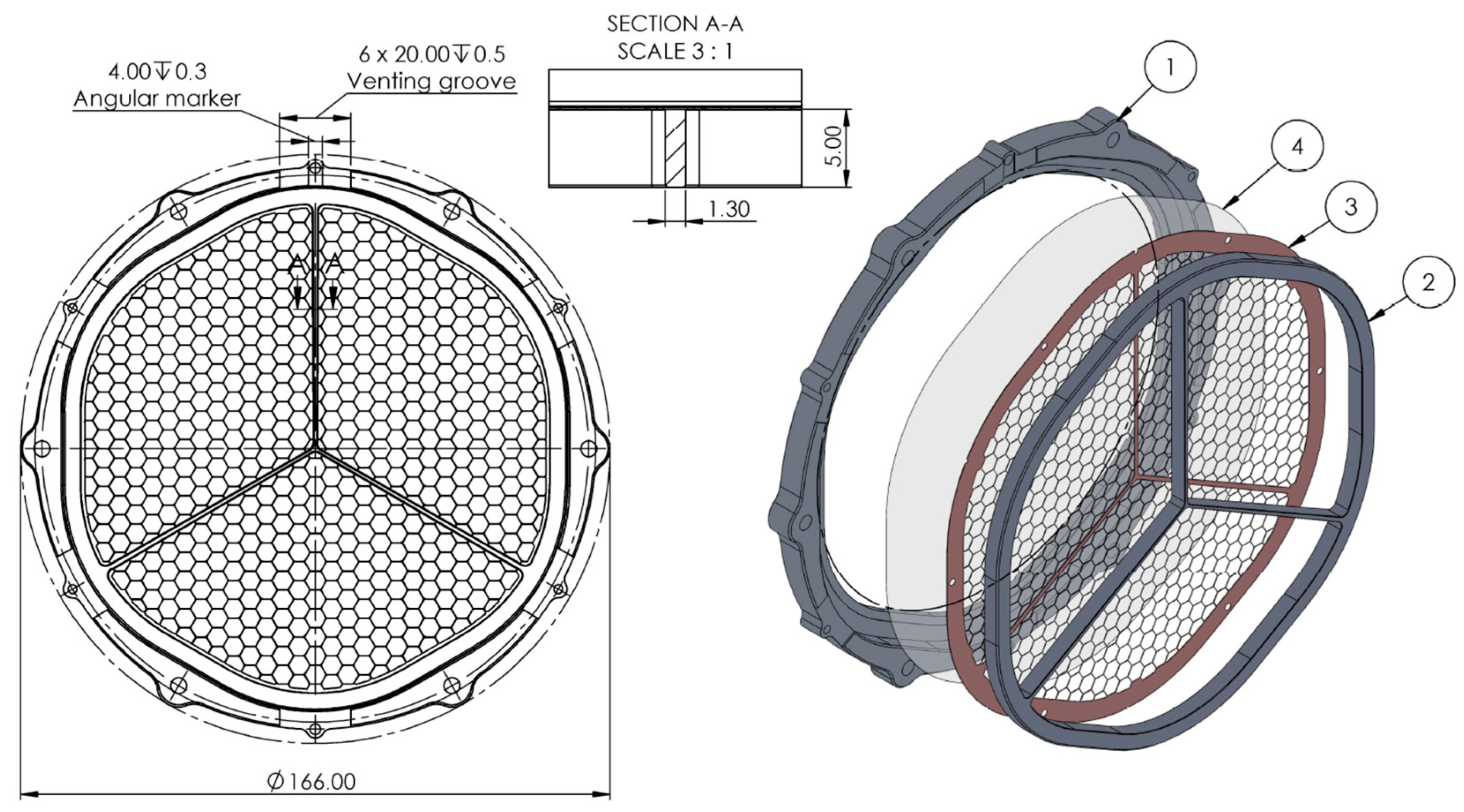
- Raising the temperature of the external frame and heating the filter by conduction through the mesh and an additional thick Y-shaped aluminum structure applied above the mesh.
- 3.
- Injecting a heat flux at the center of the filter and heating the filter by conduction through the mesh;
- 4.
- Running an electrical current through the mesh from the center to the external frame and heating the filter via a distributed Joule heating.
3. Thermal Modeling
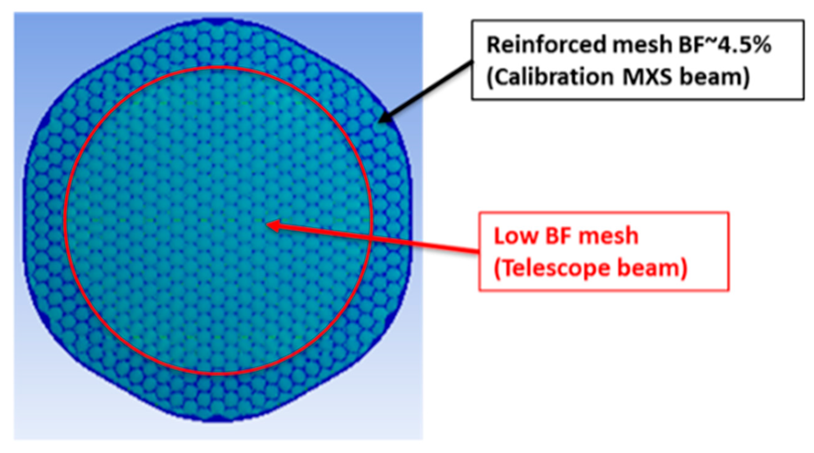
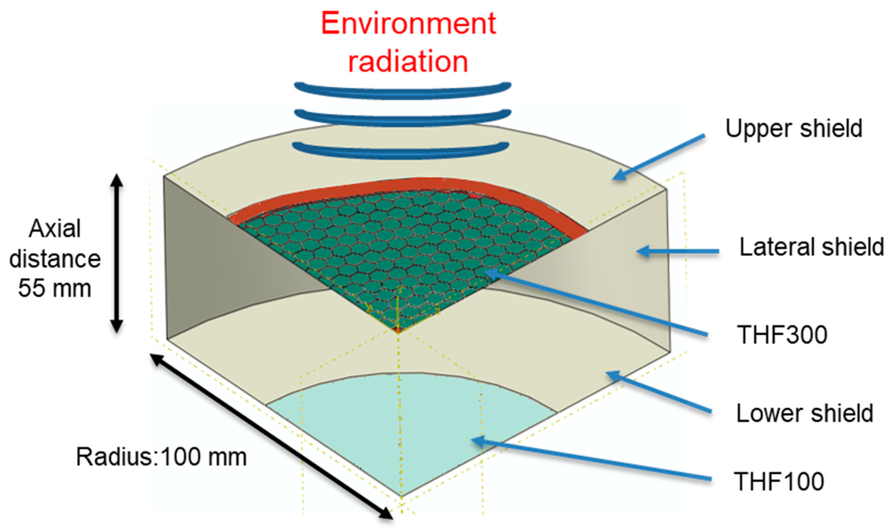
3.1. Numerical Simulation Geometry and Assumptions
3.2. Material Properties
- -
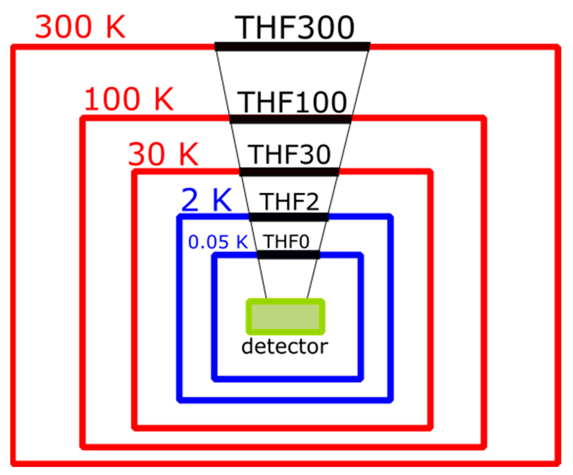
- The geometries simplification on the cavity and on the THF100;
- -
- The THF100 boundary conditions (The THF100 is kept at fixed temperature);
- -
- The cross-section of the mesh arm is considered nominal (manufacturing processes could affect the real geometry;
- -
- The perfect contact between the mesh/film and external frame/carrier;
- -
- Uncertainty of the thermal conductivity of the materials (the purity of the metals can affect the thermal conductivity; see Al 5N [25]).
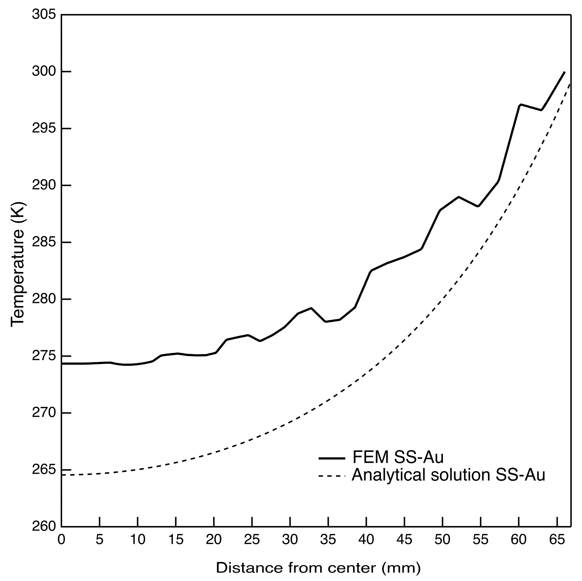
3.3. Comparison with an Analytical Model
4. Results and Discussion
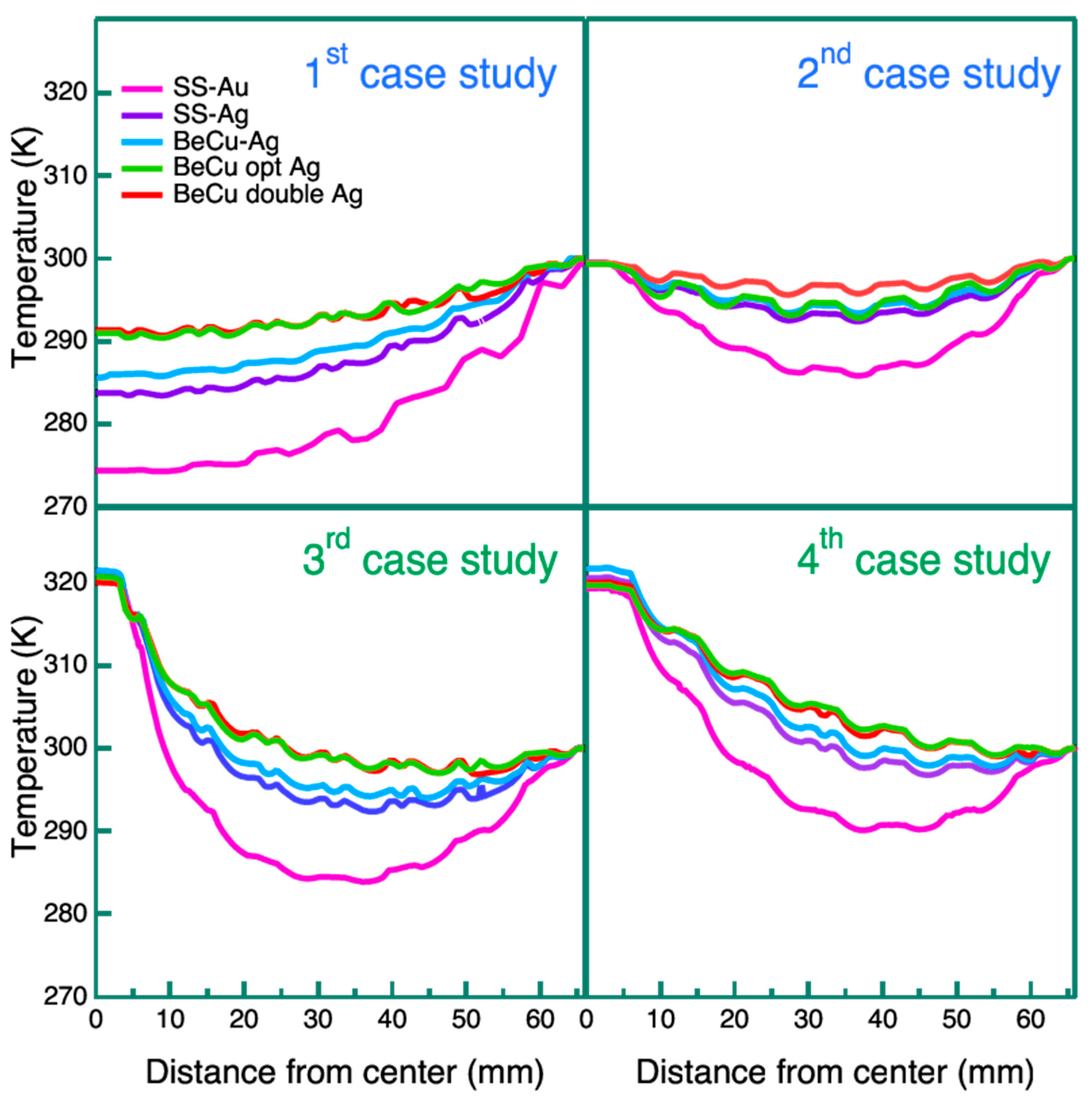
4.1. External Frame at 300 K
4.2. Minimum Temperature of 320 K
5. Conclusions
Author Contributions
Funding
Data Availability Statement
Acknowledgments
Conflicts of Interest
References
- Barcons, X.; Nandra, K.; Barret, D.; Herder, J.-W.D.; Fabian, A.C.; Piro, L.; Watson, M.G.; The Athena team. Athena: The X-ray observatory to study the hot and energetic Universe. J. Phys. Conf. Ser. 2015, 610, 012008. [Google Scholar] [CrossRef]
- Nandra, K.; Barret, D.; Barcons, X.; Fabian, A.; Herder, J.W.D.; Piro, L.; Watson, M.; Adami, C.; Aird, J.; Afonso, J.M.; et al. The Hot and Energetic Universe: A White Paper presenting the science theme motivating the Athena+ mission. arXiv 2013, arXiv:1306.2307. [Google Scholar]
- Bavdaz, M.; Wille, E.; Ayre, M.; Ferreira, I.; Shortt, B.; Fransen, S.; Millinger, M.; Collon, M.J.; Vacanti, G.; Barrière, N.M.; et al. ATHENA optics technology development. In Proceedings of the SPIE Astronomical Telescopes + Instrumentation, Montréal, QC, Canada, 17–23 July 2022; Volume 12181, p. 121810T. [Google Scholar] [CrossRef]
- Barret, D.; Albouys, V.; Herder, J.-W.D.; Piro, L.; Cappi, M.; Huovelin, J.; Kelley, R.; Mas-Hesse, J.M.; Paltani, S.; Rauw, G.; et al. The Athena X-ray Integral Field Unit: A consolidated design for the system requirement review of the preliminary definition phase. Exp. Astron. 2023, 55, 373–426. [Google Scholar] [CrossRef]
- Meidinger, N.; Nandra, K.; Plattner, M. Development of the Wide Field Imager instrument for ATHENA. In Proceedings of the SPIE Astronomical Telescopes + Instrumentation, Austin, TX, USA, 10–15 June 2018; Volume 10699, p. 106991F. [Google Scholar] [CrossRef]
- Barbera, M.; Hartog, R.H.D.; Varisco, S.; Barret, D.; Branduardi-Raymont, G.; Buttacavoli, A.; Cappi, M.; Collura, A.; Cuttaia, F.; D’Anca, F.; et al. ATHENA X-IFU thermal filters development status toward the end of the instrument phase-A. In Proceedings of the SPIE Astronomical Telescopes + Instrumentation, Austin, TX, USA, 10–15 June 2018; p. 106991R. [Google Scholar]
- Charles, I.; Daniel, C.; André, J.; Duband, L.; Duval, J.M.; den Hartog, R.; Mitsuda, K.; Shinozaki, K.; van Weers, H.; Yamasaki, N.Y. Preliminary thermal architecture of the X-IFU instrument dewar. In Proceedings of the SPIE Astronomical Telescopes + Instrumentation, Edinburgh, UK, 26 June–1 July 2016; p. 99052J. [Google Scholar] [CrossRef]
- Thibert, T.; Jacques, L.; Terrasa, G.; Lallemand, E.; Rauw, G.; Kintziger, C. Aperture cylinder on Athena X-IFU: Development status. In Proceedings of the SPIE Astronomical Telescopes + Instrumentation, Montréal, QC, Canada, 17–23 July 2022; Volume 12181, p. 121810O. [Google Scholar]
- Barbera, M.; Collura, A.; Gatti, F.; Cicero, U.L.; Macculi, C.; Piro, L.; Renotte, E.; Sciortino, S. Baseline design of the thermal blocking filters for the X-IFU detector on board ATHENA. In Proceedings of the SPIE Astronomical Telescopes + Instrumentation, Montréal, QC, Canada, 22–27 June 2014; Volume 9144, p. 91445U. [Google Scholar] [CrossRef]
- Plucinsky, P.P.; Bogdan, A.; Germain, G.; Marshall, H.L. The evolution of the ACIS contamination layer over the 16-year mission of the Chandra X-ray Observatory. In Proceedings of the SPIE Astronomical Telescopes + Instrumentation, Edinburgh, UK, 26 June–1 July 2016; Volume 9905, p. 990544. [Google Scholar]
- Marshall, H.L.; Tennant, A.; Grant, C.E.; Hitchcock, A.P.; O’Dell, S.L.; Plucinsky, P.P. Composition of the Chandra ACIS contaminant. In Proceedings of the Optical Science and Technology, SPIE’s 48th Annual Meeting, San Diego, CA, USA, 3–8 August 2003; Volume 5165, pp. 497–509. [Google Scholar]
- Kilbourne, C.A.; Adams, J.S.; Arsenovic, P.; Ayers, T.; Chiao, M.P.; DiPirro, M.J.; Eckart, M.E.; Fujimoto, R.; Kazeva, J.D.; Kripps, K.L.; et al. Design, implementation, and performance of the Astro-H soft X-ray spectrometer aperture assembly and blocking filters. J. Astron. Telesc. Instrum. Syst. 2018, 4, 011215. [Google Scholar] [CrossRef]
- Ishisaki, Y.; The XARM Resolve Team; Ezoe, Y.; Yamada, S.; Ichinohe, Y.; Fujimoto, R.; Takei, Y.; Yasuda, S.; Ishida, M.; Yamasaki, N.Y.; et al. Resolve instrument on X-ray astronomy recovery mission (XARM). J. Low Temp. Phys. 2018, 193, 991–995. [Google Scholar] [CrossRef]
- X-IFU Design Description Volume 1: Design Summary; Report Prepared by the X-IFU Instrument Consortium (doc. N° XIFU-DD-10000-00816-CNES); X-IFU: Toulouse, France, 2022.
- Barbera, M.; Agnello, S.; Buscarino, G.; Collura, A.; Gastaldello, F.; La Palombara, N.; Lo Cicero, U.; Tiengo, A.; Sciortino, L.; Varisco, S.; et al. Status of the EPIC thin and medium filters on-board XMM-Newton after more than 10 years of operation I: Laboratory measurements on back-up filters. In Proceedings of the SPIE Astronomical Telescopes + Instrumentation, San Diego, CA, USA, 25–29 August 2013; p. 885914. [Google Scholar] [CrossRef]
- Barbera, M.; Argan, A.; Bozzo, E.; Branduardi-Raymont, G.; Ciaravella, A.; Collura, A.; Cuttaia, F.; Gatti, F.; Escobar, A.J.; Cicero, U.L.; et al. Thermal Filters for the ATHENA X-IFU: Ongoing activities toward the conceptual design. J. Low Temp. Phys. 2016, 184, 706–711. [Google Scholar] [CrossRef]
- Sciortino, L.; Lo Cicero, U.; Ferruggia Bonura, S.; D’Anca, F.; Buttacavoli, A.; Puccio, E.; Barbera, M. Thermal modelling of the ATHENA X-IFU filters. In Proceedings of the SPIE Astronomical Telescopes + Instrumentation, Austin, TX, USA, 10–15 June 2018; Volume 10699. [Google Scholar]
- Beryllium-Copper Alloy 25 (C17200) Strip MATERION Datasheet. Available online: https://hkvxni.files.cmp.optimizely.com/download/b97f9c2aa04211eeb43acac3311fc08f (accessed on 2 April 2024).
- Barbera, M.; Cicero, U.L.; Sciortino, L.; Magnano, E.; Píš, I.; Ciaravella, A.; Collura, A.; Escobar, A.J.; Levantino, M.; Nuzzo, F. Temperature effects on the performances of the ATHENA X-IFU thermal filters. In Proceedings of the SPIE Astronomical Telescopes + Instrumentation, Edinburgh, UK, 26 June–1 July 2016; p. 990560. [Google Scholar] [CrossRef]
- Beryllium-Copper Alloy 3 (C17510) Strip MATERION Datasheet. Available online: https://hkvxni.files.cmp.optimizely.com/download/ba846a56a04211ee87612a5d2cb825d4 (accessed on 2 April 2024).
- Herve, P.; Rambure, N.; Sadou, A.; Ramel, D.; Francou, L.; Delouard, P.; Gavila, E. Direct measurement of total emissivities at cryogenic temperatures: Application to satellite coatings. Cryogenics 2008, 48, 463–468. [Google Scholar] [CrossRef]
- Giulietti, D.; Lucchesi, M. Emissivity and absorptivity measurements on some high-purity metals at low temperatures. J. Phys. D Appl. Phys. 1981, 14, 877–881. [Google Scholar] [CrossRef]
- Touloukian, Y.S.; Buyco, E.H. Thermophysical Properties of Matter—TPRC—Vol 1. 1970. Available online: https://trc.nist.gov/cryogenics/materials/304Stainless/304Stainless_rev.htm (accessed on 2 April 2024).
- Rule, D.L.; Smith, D.R.; Sparks, L.L. Thermal Conductivity of a Polyimide Film Between 4.2 and 300K, with and without Alumina Particles as Filler. 1990. Available online: https://www.govinfo.gov/content/pkg/GOVPUB-C13-daa2161b64da3a0d59fc65175a9eda23/pdf/GOVPUB-C13-daa2161b64da3a0d59fc65175a9eda23.pdf (accessed on 2 April 2024).
- Woodcraft, A.L. Recommended values for the thermal conductivity of aluminium of different purities in the cryogenic to room temperature range, and a comparison with copper. Cryogenics 2005, 45, 626–636. [Google Scholar] [CrossRef]
- Smith, D.R.; Fickett, F.R. Low-Temperature Properties of Silver. J. Res. Natl. Inst. Stand. Technol. 1995, 100, 119–171. [Google Scholar] [CrossRef] [PubMed]
- Simon, N.J.; Drexler, E.S.; Reed, R.P. Properties of Copper and Copper Alloys at Cryogenic Temperatures; NIST Monograph 177; National Institute of Standards and Technology (MSEL): Boulder, CO, USA, 1992. [Google Scholar]
- LNG Materials & Fluids: A User’s Manual of Property Data in Graphic Format. 1977. Available online: https://apps.dtic.mil/sti/citations/ADD095454#:~:text=In%20this%20first%20edition%2C%20those,evaluated%20data%2C%20with%20additional%20properties (accessed on 2 April 2024).
- Jacques, L. Athena X-IFU—Aperture Cylinder Preliminary Thermal Analyses 2018; Report Prepared by the X-IFU Instrument Consortium (doc. N° XIFU-TN-AC-001); X-IFU: Toulouse, France, 2018. [Google Scholar]
- Powell, R.W.; Ho, C.Y.; Liley, P.E. Thermal Conductivity of Selected Materials; US Government Printing Office: Washington, DC, USA, 1966.


| Case Study | Description | Heating Strategy | Note |
|---|---|---|---|
| 1st | Effects of mesh and plating material | Passive conduction | External frame at 300 K |
| 2nd | Additional Y-cross over the mesh | ||
| 3rd | Heat flux injected on the filter center | Active heating | |
| 4th | Joule heating by running a current | ||
| 5th | 1st study + external frame heating | Passive conduction | Requirement to meet T > 320 K throughout the filter surface |
| 6th | 2nd study + external frame heating | ||
| 7th | 3rd study + external frame heating | Active heating | |
| 8th | 4th study + external frame heating |
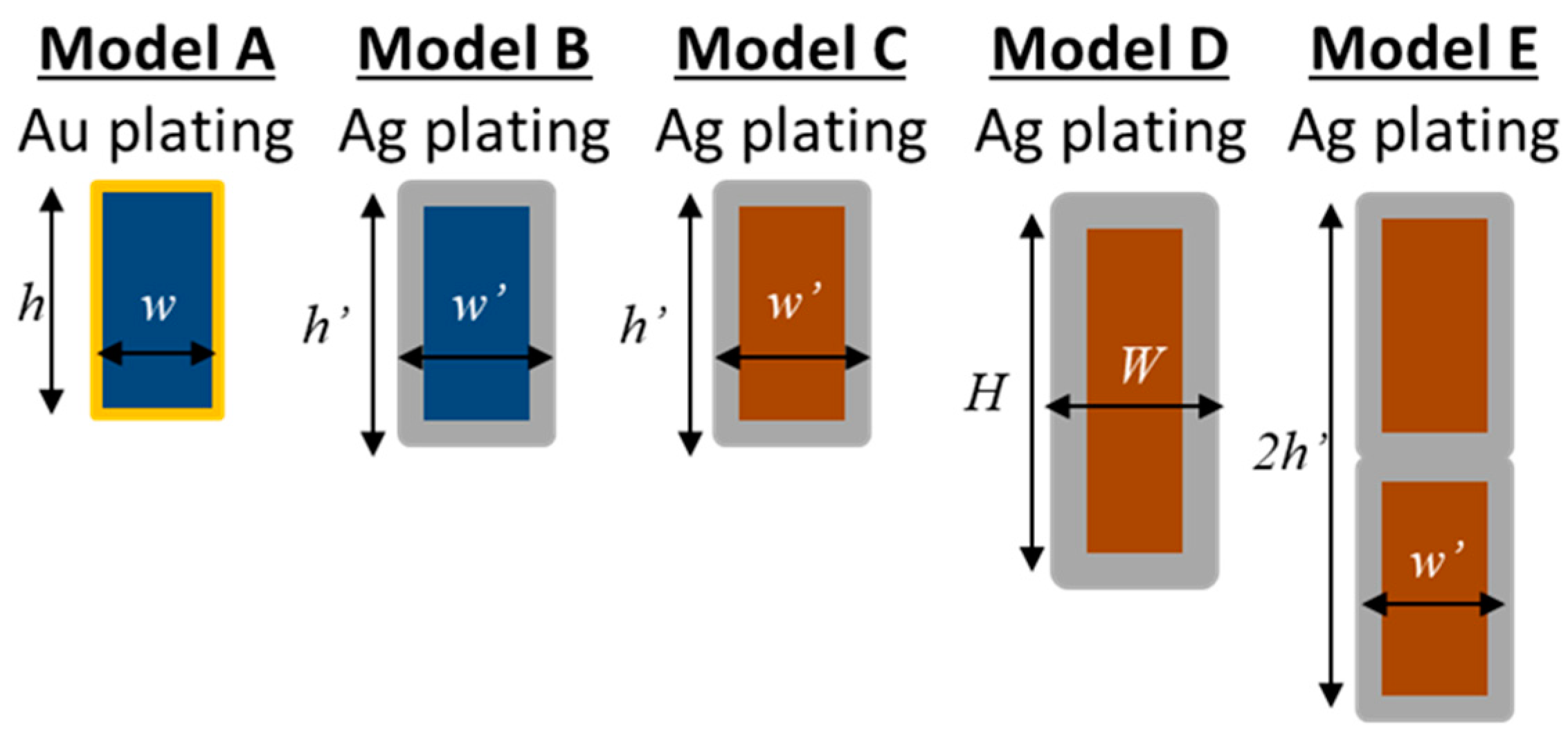
| Model | Mesh Material (Single/Double) | Plating Material and Thickness [μm] | Mesh Bar Size h × w (h × w Plated) [μm] | Blocking Factor (%) |
|---|---|---|---|---|
| A—SS Au | SS AISI304 (single) | Au 5 | 80 × 40 (90 × 50) | 2.37 |
| B—SS Ag | SS AISI304 (single) | Ag 10 | 80 × 40 (100 × 60) | 2.75 |
| C—BeCu Ag | BeCu C17200 alloy (single) | Ag 10 | 80 × 40 (100 × 60) | 2.75 |
| D—BeCu opt Ag | BeCu C17510 alloy (single) | Ag 15 | 80 × 40 (110 × 70) | 3.1 |
| E—BeCu double Ag | BeCu C17200 alloy (double) | Ag 10 | 160 × 40 (200 × 60) | 2.75 |
| Thermal Conductivity [W/m K] at 300 K [28] | |||||||
|---|---|---|---|---|---|---|---|
| Al 5N | Gold 5N | AISI304 (SS) | Al oxide | Polyimide | Silver 5N | BeCu C17200 | BeCu C17510 |
| 405 | 310 | 15.31 | 32 | 0.192 | 427 | 105 | 240 |
| Model | Heat Flux [mW/mm2] | Deposited Power [mW] |
|---|---|---|
| A SS-Au | 0.8 | 17.6 |
| B SS-Ag | 1.5 | 33 |
| C BeCu-Ag | 1.7 | 37.4 |
| D BeCu opt Ag | 2.3 | 51 |
| E BeCu double Ag | 2.5 | 55 |
| Model | Voltage [mV] | Dissipated Energy [mW] |
|---|---|---|
| A SS-Au | 36 | 10 |
| B SS-Ag | 34 | 16 |
| C BeCu-Ag | 40 | 19 |
| D BeCu opt Ag | 22 | 26 |
| E BeCu double Ag | 25 | 26 |
| Model | Heat Flux [mW/mm2] | Deposited Power [mW] |
|---|---|---|
| A SS-Au | 2 | 44 |
| B SS-Ag | 1.8 | 39.6 |
| C BeCu-Ag | 1.8 | 39.6 |
| D BeCu opt Ag | 1.5 | 33 |
| E BeCu double Ag | 1.6 | 35.2 |
| Model | Voltage [mV] | Dissipated Energy [mW] |
|---|---|---|
| A SS-Au | 50 | 20 |
| B SS-Ag | 35 | 17 |
| C BeCu-Ag | 28 | 9 |
| D BeCu opt Ag | 22 | 14 |
| E BeCu double Ag | 19 | 15 |
Disclaimer/Publisher’s Note: The statements, opinions and data contained in all publications are solely those of the individual author(s) and contributor(s) and not of MDPI and/or the editor(s). MDPI and/or the editor(s) disclaim responsibility for any injury to people or property resulting from any ideas, methods, instructions or products referred to in the content. |
© 2024 by the authors. Licensee MDPI, Basel, Switzerland. This article is an open access article distributed under the terms and conditions of the Creative Commons Attribution (CC BY) license (https://creativecommons.org/licenses/by/4.0/).
Share and Cite
Montinaro, N.; Sciortino, L.; D’Anca, F.; Lo Cicero, U.; Bozzo, E.; Paltani, S.; Todaro, M.; Barbera, M. Thermalization of Mesh Reinforced Ultra-Thin Al-Coated Plastic Films: A Parametric Study Applied to the Athena X-IFU Instrument. Sensors 2024, 24, 2360. https://doi.org/10.3390/s24072360
Montinaro N, Sciortino L, D’Anca F, Lo Cicero U, Bozzo E, Paltani S, Todaro M, Barbera M. Thermalization of Mesh Reinforced Ultra-Thin Al-Coated Plastic Films: A Parametric Study Applied to the Athena X-IFU Instrument. Sensors. 2024; 24(7):2360. https://doi.org/10.3390/s24072360
Chicago/Turabian StyleMontinaro, Nicola, Luisa Sciortino, Fabio D’Anca, Ugo Lo Cicero, Enrico Bozzo, Stéphane Paltani, Michela Todaro, and Marco Barbera. 2024. "Thermalization of Mesh Reinforced Ultra-Thin Al-Coated Plastic Films: A Parametric Study Applied to the Athena X-IFU Instrument" Sensors 24, no. 7: 2360. https://doi.org/10.3390/s24072360
APA StyleMontinaro, N., Sciortino, L., D’Anca, F., Lo Cicero, U., Bozzo, E., Paltani, S., Todaro, M., & Barbera, M. (2024). Thermalization of Mesh Reinforced Ultra-Thin Al-Coated Plastic Films: A Parametric Study Applied to the Athena X-IFU Instrument. Sensors, 24(7), 2360. https://doi.org/10.3390/s24072360